Table of Contents
Advertisement
2
Index
CARLO GAVAZZI
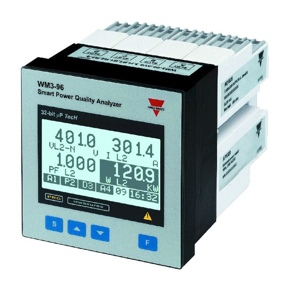
WM3-96
32bit
-Processor based power quality analyser with
modular housing for Plug and Play modules
FW rev. 12
Instruction manual: INDEX
TO BEGIN WITH ................................................................ 5
The main programming parameters .......................... 5
Front panel description ............................................. 6
Display adjustment .................................................... 6
DISPLAYING OF THE VARIABLES ................................... 7
Page "00", starting page ........................................... 7
How to scroll the display pages ................................ 8
display page .............................................................. 8
and MAX values ................................................. 8
harmonic analysis .............................................. 9
Displaying of the Energy meters ....................... 10
Page "25": displaying of the total energy meters ......... 10
Page "27": displaying of the instrument's configuration 11
Displaying with access to the pass code .......... 11
Pass "999": energy consumption storage ......... 12
LET'S START ................................................................. 13
Main menu .............................................................. 13
Changing the password .......................................... 14
Electrical system ..................................................... 14
CT ratio ................................................................. 15
VT ratio ................................................................. 16
Display page ........................................................... 16
How to use the symbols
4
4
Advertisement
Table of Contents

Subscribe to Our Youtube Channel
Related Manuals for CARLO GAVAZZI WM3-96 - PROGRAMMING


Summary of Contents for CARLO GAVAZZI WM3-96 - PROGRAMMING
-
Page 1: Table Of Contents
Index CARLO GAVAZZI WM3-96 32bit -Processor based power quality analyser with modular housing for Plug and Play modules FW rev. 12 Instruction manual: INDEX TO BEGIN WITH ..............5 The main programming parameters ......5 Front panel description ..........6 Display adjustment ............ - Page 2 Index MIN MAX values ............. 17 Selecting the events ..........18 Average values calculation ........19 ENERGY METERS MANAGEMENT ........ 22 Access to the management menu of the energy meters ..22 Single tariff management ........22 Dual tariff Management: whole year ....22 Programming of the holidays period ....
- Page 3 Index V/mA single analogue outputs ......49 V/mA dual analogue outputs ......49 Relay output ............. 50 Open collector output ........50 Digital inputs ............. 50 RS485 serial output .......... 51 ELECTRICAL DIAGRAMS ..........52 Electrical connection diagrams ....... 52 Three-phase connection, Balanced load ..
-
Page 4: To Begin With
To begin with Go to the page where the subject written on the bottom of the current page starts. This symbol indicates a particularly important subject or information. This symbol indicates that more details are given on the current subject. We suggest you to keep the original pack- ing in case it is necessary to return the instrument to our Technical Service De-... -
Page 5: Front Panel Description
To begin with Front panel description Exit from the menu and cancel the choice you have made. It allows you to access some functions relating displayed variables. Scroll to the previous page. Access to programming Scroll to the or settings’ confirmation. next page. -
Page 6: Displaying Of The Variables
Displaying of the variables Page “00”, Starting page When the instrument is switched on, the main page of variable displaying is shown. This first page, called page "00", is the only one configurable by the user who can choose the variables to be displayed in the 4 displaying areas. -
Page 7: How To Scroll The Display
Displaying of the variables How to scroll the various pages To scroll the various pages, use the keys. Pressing the key in any one of the display pages, you access to the programming phase. The key, on the contrary, has various functions depending on the selected page. -
Page 8: Pages From "19" To "24": Displaying Of The Harmonic Analysis
Displaying of the variables Pages from "19" to "24" (10 to 11 in single phase mode) Displaying of the harmonic analysis When the instrument is supplied, these pages are not enabled, see page 29 to enable them.The key is active, access to the detailed analysis of the harmonics. -
Page 9: Displaying Of The Energy Meters
Displaying of the variables Generated Harmonics: Imported This angle is displayed only if the measurements are taken in a three-phase system with neutral. Pages relating to the energy meters Page "25" (12 in single phase mode) Displaying of the total energy meters key disabled. -
Page 10: Displaying With Access To The Pass Code
Displaying of the variables Page “27” (14 in single phase mode) Displaying of instrument configuration key disabled. Page 27 shows the configuration of the main input (IN) and output (OUT) modules. Alarms (A1-A2-A3-A4). Diagnostics (D1-D2-D3-D4). Pulse outputs (P1-P2-P3-P4). Digital inputs. The letters and numbers between parenthesis are referred to the relevant slot, while the text on their right shows the variable referred to the output. -
Page 11: Pass "999": Energy Consumption Storage
Displaying of the variables Control type: Only for alarms and diag- alarm (e.g. A2), nostics: detection of the diagnostics (e.g. D1), abnormal condition (ON) maximum value (MAX), or return to the normal con- minimum value (MIN). dition (OFF). Variable being controlled. -
Page 12: Let's Start
Let’s start Use the keys to show the partial values, to exit press the key. It is very important to verify that, every time the configuration of the instrument (modules and/or associated variables, electrical systems, etc.) changes, the setting of the parameters is according to the new configuration. -
Page 13: Changing The Password
Let’s start Changing the password This function allows you to choose the desired password value (from 0 to 500). Press the key and when the new password value is required, enter the desired value by means of keys. The instrument goes back to the main menu, as shown on the figure on the left. -
Page 14: Ct Ratio
Let’s start To reset the choice and go back to the main menu, press the key. Changing the type of system, all the MIN/MAX values, the events and the partial energy meters are reset. CT ratio This function allows you to select the value of the CT ratio. -
Page 15: Vt Ratio
Let’s start VT ratio This function allows the user to se- lect the multiplier value of the VT. Example: if the primary of the VT (voltage transformer) being con- nected is 20kV and the secondary is 100V, the VT ratio will be 200 (given by 20000/100). -
Page 16: Min Max Values
Let’s start Press ; select the variable to be displayed by means of the keys and confirm it with To reset your choices and go back to the main menu press Measure MIN/MAX VALUES This function allows the user to as- sociate some variables to the auto- matic recording of maximum values (from MAX1 to MAX12) and mini-... -
Page 17: Selecting The Events
Let’s start Scroll the list of the variables using keys; once you have selected the desired variable, confirm it using . To reset your choices and go back to the main menu, press Once you have con- firmed the selection, the following message will appear: “YOUR CHOICE WILL RESET THE VARIABLE, WILL YOU... - Page 18 Let’s start To use this function, select “EVENTS SELECT.” from the main menu us- ing the keys and con- firm it pressing . Use the keys to select where you want to enable the event (ON) or disable it (OFF). The function of the OFF-ON key is cyclical.
- Page 19 Let’s start FIXED SELECTION: if, e.g., you set this value at 15 minutes, the instrument calculates and up- dates the average of the variables (W-VA-PF) every 15 minutes. FLOAT SELECTION: if, e.g., you set this value at 15 min- utes, the instrument at first calculates and updates the average of the variable (W-VA-PF) after 15 minutes and then every minute (fixed time).
- Page 20 Let’s start FIXED AVERAGE CALCULATION Where: Pmax is the maximum measured power Pc is the contractual power, t1 is the selected average period FLOAT AVERAGE CALCULATION Average power calculation Holiday period...
-
Page 21: Energy Meters Management
Energy Meters Management Access to the Energy Meters Management Menu This function allows you to choose the type of management of the en- ergy meters. Select “ENERGY ME- TERS” from the main menu by TARIFF SELECTION means of the keys; confirm with to access the spe- cific secondary menu. -
Page 22: Reset Of The Energy Meters
Energy Meters Management 3- press the key again; the “end- tariff” hour is highlighted; 4- press the key again; the HOURS box will appear on the lower part of the display; now you can choose the hours - e.g. 8 - by means of the keys. - Page 23 Energy Meters Management a) the day can be divided into up to 8 different periods connected to up to 4 different tariffs according to the following working principle: trf1 Imported active energy + kWh Exported active energy - kWh Imported reactive energy + kvarh Exported reactive energy - kvarh...
- Page 24 Energy Meters Management PROGRAMMING THE HOLIDAY PERIOD To program the HOLIDAY period, proceed in the following way. 10- Choose HOLIDAY in the SEA- SON menu by means of the keys and confirm with the HOLIDAY menu will be displayed (see figure on the left); 11-press : the month correspond- ing to the start date will be highlighted;...
- Page 25 Energy Meters Management To program the “end date” follow the same procedure de- scribed above from No. 11 to No. 16. After confirming the “end” day by means of the key, the HOLIDAY box is highlighted to indicate the conclusion of the HOLIDAY period program- ming cycle.
- Page 26 Energy Meters Management MULTI TARIFF This function allows the management of the meters according to many periods per day and three periods per year: WINTER, SUMMER and HOLIDAY. To program the parameters relating to the winter season, simply follow the same procedure (holidays) de- scribed on page 25 from No.
- Page 27 Energy Meters Management DUAL TARIFF management trf1 trf1 WHOLE YEAR WHOLE YEAR start OO:OO O8:OO O8:OO 2O:OO OO:OO 2O:OO TARIFF trf2 As you can see on the figure above, there is a daily division into three periods with two different tariffs. MULTI TARIFF management WINTER start...
- Page 28 Outputs / Other settings To conclude the RESET procedure, press ; to go back to the TARIFF SELECTION menu, press The reset procedure allows the user to choose among the following different choices: ALL: reset of all the energy meters (imported/ exported energies);...
-
Page 29: Clock Setting
Outputs / Other settings Clock setting This function enables the user to set the data relating to date and time. Select CLOCK from the main menu by means of the keys; then press to enter the menu. Choose the desired function by means of the keys;... -
Page 30: Pulse Output
Outputs / Other settings DIAGNOSTIC OUTPUT, REMOTE CONTROL OUTPUT. To enter these functions, choose DIGITAL OUTPUT from the main menu using the keys, then confirm with . The instrument shows a window where the various slots (OUT C0, OUT C1, etc.) and output channels (1, 2, etc.) are shown. -
Page 31: Alarms
Outputs / Other settings consumed active energy (kWh +), generated active energy (kWh -), consumed reactive energy (kvarh +), generated reactive energy (kvarh -), press the “ ” key to open the menu of energy/pulse output management. There are five possible selections: TOTAL, output connected to the total energy meter;... - Page 32 Outputs / Other settings choose among all the available ones (see on page 43); scroll the variables by means of the keys and confirm the selection with . The avail- ability (or non-availability) of the variable is clearly indicated on the display. •TYPE: type of alarm: up alarm (UP);...
-
Page 33: Remote Control
Outputs / Other settings Diagnostic In a 3-phase unbalanced-load sys- tem, this function controls the presence of the neutral connection. If the connection to the neutral is not detected, the instrument activates an alarm. Select “DIAGNOSTIC” by means of the keys, then press to confirm it. -
Page 34: Analogue Outputs
Outputs / Other settings Analogue outputs Select ANALOG OUTPUTS from the main menu by means of the keys; confirm it with to enter the various parameters: OUT A0: Analogue output, SLOT A0, channel 1; OUT A1: Analogue output, SLOT A1, channel 2; OUT B0: Analogue output, SLOT B0, channel 3;... - Page 35 Outputs / Other settings •MIN IN: minimum value of the variable input range. Select the desired value by means of the keys and confirm it with •MAX IN: maximum value of the variable input range. Select the desired value by means of the keys and confirm it with .
-
Page 36: Digital Filter
Outputs / Other settings Digital filter Select FILTER by means of and confirm with . Select the function to be set from one of the submenus by means of the keys and confirm it with You can choose among the follow- ing 3 selections: •... -
Page 37: Useful Information
Useful information The variables measured by the instrument are correct if the inputs have been connected ac- cording to the right polarities (see figure below). Should the connection not be conforming to the right polarities, measuring and retransmission errors may occur, both due to the wrong direction of the current flowing in the primary/secondary of the ammeter trans- former being connected. - Page 38 Useful information selected by the instrument depending on the selected VT and CT value; Example 2: it’s necessary to measure both the consumed active power and the generated active power up to 100kW and retransmit it with a signal from –10 to 10V; the module to be used is AO1033 (2x 10VCC) or AO1057 (1x 10VCC).
- Page 39 Useful information • MIN U.: 0,0% • MAX U.: 100% • MIN IN: C 0,000; the values entered with a negative sign correspond to C, those entered with a positive sign corre- spond to L; • MAX IN: L 0,001; the values entered with a negative sign correspond to C, those entered with a positive sign corre- spond to L;...
- Page 40 Useful information What is ASY The ASY variable allows to control the symmetry of the star / delta voltages (for systems without neutrals) and star voltages (for systems with neutral). The variable is calculated as fol- lows: where the first formula is to be applied with delta systems, while the minimum value calculated between the two is to be used for the star systems.
- Page 41 Useful information The configuration shown in the tables above is only valid for connections to 3-phase systems with neutral. In case of any other system, the type and quantity of the displayed variables will vary. Analogue outputs Removal of the modules...
-
Page 42: Preliminary Operations
Useful information List of the available variables: The availability of the variables depends on the type of electrical system being selected. INSTALLATION Preliminary operations Before switching the instrument on, make sure that the power supply voltage corresponds to what is shown on the side label of the relevant module. - Page 43 Installation For a correct mounting of the instrument, insert the modules in the relevant slots, then, at the end, enter the central module, which can be a blind type module or an RS232communication module. The central module will help fixing also the other modules in the relevant slots. To remove the modules use a screwdriver as shown in the picture below: Remove the central Gently depress the...
-
Page 44: Overall Dimensions And Panel Cutout
Installation Overall dimensions and panel cut-out Mounting Insert the instrument (holding its front) and fasten it (from the back) by fixing the two lateral brackets (1) (supplied with the instrument) to the appropriate location (2), using the two screws (3) supplied with the instrument. -
Page 45: Position Of The Slots And Relevant Modules
Installation Position of the slots and relevant modules Available modules Analogue output modules AO1050 (20mADC) AO1051 (10VDC) AO1052 ( 5mADC) AO1053 ( 10mADC) AO1054 ( 20mADC) AO1055 ( 1VDC) AO1056 ( 5VDC) AO1057 ( 10VDC) Single output What is ASY? Other modules... - Page 46 Installation l a i l a i e l l e l l e l l AO1026 (20mADC) AO1027 (10VDC) AO1028 ( 5mADC) AO1029 ( 10mADC) AO1030 ( 20mADC) AO1031 ( 1VDC) AO1032 ( 5VDC) AO1033 ( 10VDC) Dual output Mounting Serial connections...
-
Page 47: Digital Output Modules
Installation Digital output modules AO1058 AO1035 AO1059 AO1036 Single relay Dual relay Single open Dual open output output collector collector output output Other input/output modules AO1037 AQ1038 AR1034 4 open 3 digital RS485 collector inputs Serial outputs output AR1039 RS232 + RTC output Digital input connections Installation... -
Page 48: Power Supply Modules
Installation Power supply modules AP1020 AP1021 90 - 260 VAC/DC 18 - 60 VAC/DC power supply power supply Connection of optional modules mA/V single analogue outputs mA/V dual analogue outputs Three-phase connections Modules... -
Page 49: Relay Output
Installation Single and double relay outputs Open collector outputs This diagram is valid also for the open collec- tor modules with a lower number of outputs. The value load resistances (Rc) must be chosen so that the short-circuit current is lower than 100mA;... -
Page 50: Serial Outputs
Installation RS485 Serial outputs 4-wire connection. Additional devices provided with RS485 (that is RS 1, 2,3 ...N) are connected in parallel. 2-wire connection. Additional devices provided with RS485 (that is RS 1,2,3,...N) are connected in parallel. The termination of the serial output is carried out only on the last instrument of the network, by means of a jumper between (Rx+) and (T). -
Page 51: Electrical Diagrams
Electrical diagrams Electrical connection diagrams Three-phase connections, Balanced load Direct connection CT connection (3-wire system) (3-wire system) CT and VT connection Direct connection (3-wire system) (4-wire connection) 3/4-wire three phase Modules... - Page 52 Electrical diagrams Three phase, Balanced load CT connections CT and VT connections (4-wire system) (4-wire system) Three-phase, 4 wires - Unbalanced load CT connection Direct connection (4-wire system) (4-wire system) Serial connection Additional errors...
- Page 53 Electrical diagrams 3/4-wire three-phase connections, Unbalanced load CT and VT connection CT and VT connection (4-wire system) (3-wire system) 3-phase / 3-wires ARON connection Unbalanced load CT connection CT and VT connection (3-wire system) (3-wire system) Power supply modules Technical characteristics...
-
Page 54: Single-Phase Connection
Electrical diagrams 3-phase / 3-wires conn. Single-phase conn. 3 CT and 3 VT connection Direct connection (3-wire system) Single-phase connection CT connection CT and VT connections Serial output Three-phase connections... -
Page 55: Technical Features
Technical features General features • Modular housing for Plug and Play modules • IP65 protection degree • 32-bit -processor based indicator and controller • TRMS measurements • Back-lighted graphic LCD display (128 x 64 dots) • 4 x 4 dgt read-out (instantaneous variables) •... - Page 56 Technical features • Reactive power (@25 C 5 C, R.H. 60% non-condensing): 0.5% (rdg + f.s.) (cos 0.5 L/C, 0.1 to 1.2 In, range AV5) or 1% rdg (cos 0.5 L/C, 0.1 to 1.2 In, range AV5). • Apparent power (@25 C 5 C, R.H. 60% non-condensing): 0.5% (rdg + f.s.) (0.1 to 1.2 In, range AV5) or 1% rdg (0.1 to 1.2 In, range AV5).
-
Page 57: Over-Load Protection
Technical features RANGE (IMPEDANCE): • AV5: 58V/100V (>500k ) - 1ADC ( 0.3VA) 58V/100V (>500k ) - 5ADC ( 0.3VA) 240V/415V (>500k ) - 1ADC ( 0.3VA) 240V/415V (>500k ) - 5ADC ( 0.3VA) • AV7: 100/170V (>500k ) - 1ADC (0.3VA) 110/170V (>500k ) - 5ADC (0.3VA) 400/690V (>500k ) - 1ADC (0.3VA) 400/690V (>500k ) - 5ADC (0.3VA) - Page 58 Technical features 0 to 10mADC, 0 to 5mADC, 0 to 10VDC, 0 to 10VDC, 0 to 5VDC, 0 to 1VDC. • Scaling factor: programmable within the whole range of retransmission; it allows the retransmission management of all values from: 0 to 20mADC, 0 to 20mADC, 0 to 10mADC, 0 to 5mADC, 0 to 10VDC, 0 to 10VDC, 0 to 5VDC, 0 to 1VDC •...
- Page 59 Technical features • Stored energy (EEPROM): max 999.999.999 kWh/kvarh • Data format: 1 start bit, 8 data bit, no parity/even parity/odd parity, 1 stop bit • Baud-rate: 1200, 2400, 4800 and 9600 baud, • Insulation: by means of optocouplers, 4000 Vrms between output and measuring inputs, 4000 Vrms between output and power supply inputs RS232 SERIAL OUTPUT (on request): •...
-
Page 60: Software Functions
Technical features ALARMS: (on request) • Number of outputs: up to four, independent • Alarm type: up alarm, down alarm, up alarm with latch, down alarm with latch, phase asymmetry, phase loss, neutral loss. • Set-point adjustment: 0 to 100% of the electrical scale •... -
Page 61: Harmonic Distortion Analysis
Technical features DIGITAL FILTER: • Operating range: 0 to 99.9% of the input scale • Filtering coefficient: 1 to 255 • Filter action: alarms, serial and analogue outputs (fundamental variables: V, A, W and their derived ones). EVENT LOGGING: only with the module RS232+RTC mod- ule. -
Page 62: Energy Management
Technical features HARMONIC DETAILS For each THD page, it’s possible to see the order of the harmonics. DISPLAY PAGES The harmonic content is displayed as a graph showing the whole harmonic spectrum. The information is given also as numerical data: THD in % / RMS value THD odd in % / RMS value THD even in %/ RMS value... -
Page 63: Power Supply Specifications
Technical features Power supply specifications AC VOLTAGE: 18 - 60 VDC/AC (on request); 90 - 260 VDC/AC (standard) POWER CONSUMPTION: 30VA / 12W (90-260V); 20VA / 12W (18-60V) General specifications OPERATING TEMPERATURE: from 0 to +50 C (R.H. <90% non-condensing) STORAGE TEMPERATURE: from -10 to +60 C (R.H.<90% non-condensing).
Need help?
Do you have a question about the WM3-96 - PROGRAMMING and is the answer not in the manual?
Questions and answers