Table of Contents
Advertisement
CARLO GAVAZZI
A u t o m a t i o n
C o m p o n e n t s
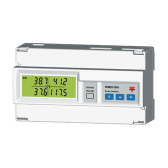
WM22-DIN: three-phase power
analyzer
Harmonic analysis; Energy meters;
Plug and play technique. These
are only a few among many other
functions performed by your
WM22-DIN. What's more,
Carlo Gavazzi means ISO9001
certification, a working experience
of many decades and a wide-
spread presence all over the world.
All this because we want our
customers to have the top service
and the top products.
Welcome in the Carlo Gavazzi
world and compliments for your
smart choice. Visit our website at:
www.carlogavazzi.com
Advertisement
Table of Contents

Related Manuals for CARLO GAVAZZI WM22-DIN


Summary of Contents for CARLO GAVAZZI WM22-DIN
- Page 1 All this because we want our customers to have the top service and the top products. Welcome in the Carlo Gavazzi world and compliments for your smart choice. Visit our website at: www.carlogavazzi.com...
-
Page 2: Table Of Contents
Index CARLO GAVAZZI WM22 DIN, three-phase power analyzer. FW rev. 02 TO BEGIN WITH ............... 04 Front panel description ........... 04 List and description of displayed measuring pages ..04 PROGRAMMING .............. 08 Access to the main menu ........08 Change password ........... -
Page 3: Index
Index How to remove the upper cover ......24 Module connections ............25 Module removal ............26 Dimensions and panel cut-out for panel mounting ..27 Open collector output connections ......28 Analogue output connections ........28 Serial output connections ........28 Electrical diagrams of 90A version ...... -
Page 4: To Begin With
To begin with Front panel description Display previous page Display next page Instrument Backlighted reference number Access to LCD display (optional indication) programming or Setting confirmation List and description of the displayed measuring pages When the instrument is PFΣ switched on, it shows the measuring page de- WΣ... - Page 5 To begin with Total harmonic distortion expressed as % for the following currents: A-L2 A-L3 A-L1 Total kWh energy meter. Total kvarh energy meter. Partial kWh energy meter. Partial kvarh energy meter. Index System...
- Page 6 To begin with V-L1 V-L2 VΣ is always 00 in case of connections without neutral V-L3 A-L1 A-L2 Err: it’s displayed in case of wrong connec- tions in one of the 3 A-L3 phases. See “Useful in- formation” on page 21. For version 20(90)A only.
- Page 7 To begin with VA-L1 VA-L2 VAΣ is always 00 in case of connections without neutral. VA-L3 VAr-L1 VAr-L2 VArΣ is always 00 in case of connections without neutral. VAr-L3 PF-L1 PF-L2 PFΣ is always 00 in case of connections without neutral. PF-L3 If displayed in the measuring mode, it means: the alarm is...
-
Page 8: Programming
Programming Access to the main menu To access to the programming menus from the measuring and dis- play phase, press the key: when the instrument asks for the pass- word, enter the correct PASS value by means of the keys; afterwards confirm by means of the key. -
Page 9: System
Programming System This function allows the operator to select the electrical system choos- ing between three-phase with neu- tral (3P.n) and three-phase without neutral (3P). Choose by means of the “SySTEn” function, press to enter the menu; then, select the desired system by means of the keys and confirm with CT ratio... -
Page 10: Vt Ratio
Programming VT ratio This function allows the user to se- lect the value of the VT ratio. Exam- ple: if the primary of the connected VT (voltage transformer) is of 20kV and the secondary is 100V, the VT ratio will correspond to 200 (obtained by carrying out the following calcu- 1.2.. -
Page 11: Total Harmonic Distortion
Programming If for example, you select the value “15 minutes”, the instrument calculates the demand value and updates the value every 15 minutes. See the diagram below. Where: Pc is the contractual power t1 is the selected integration period SYNCHRONIZATION OF THE POWER DEMAND CALCULATION The beginning of the synchronization and as a consequence the start of the integration time counting are carried out when... -
Page 12: Digital Outputs
Programming Digital Outputs Digital Output 1 This function enables to set the pa- rameters of the open collector dig- ital outputs. Choose the “diGout” function by means of the keys, to enter the menu press . Then, you may set the follow- ing parameters: ACt EnE: enable the retransmission of the active energy by means of... -
Page 13: Alarm Digital Output
Programming Alarm Digital Output This function allows the user to set the parameters of the alarm digital output. Choose the “diGout1- ALr ” function by means of the keys: to enter the menu press Then, you may set the following pa- rameters: VAr: choose the variable to be asso- ciated to the alarm activation by... -
Page 14: Digital Output 2
Programming From digital output 1, Digital output 2 rEn,PuL,SEC page 12 ACt EnE: enables the retransmission of the active energy by means of pulses; confirm with and after- wards set the number of pulses (see table on page 21) by means of the keys and confirm the value with rEA EnE: enable the retransmission... - Page 15 Programming input range. Select the desired value by means of the keys and confirm it with 1.2..2.1 LoA: % value of the zero of the output range (0-20mA, 0-10V) that is generated by the minimum meas- ured value (LoE). Select the desired 1.2..
-
Page 16: Digital Filter
Programming Digital Filter Select “FiLtEr” by means of the keys: to enter the menu press . Select the parameters to be set with the keys, to enter the menu press There are two parameters: 1.2.. - rnG, to set the operating range of ..2.1 the digital filter. -
Page 17: Reset Of Partial Meter
Programming Reset of partial meters Select “rESEt Prt” from the main menu by means of the keys, confirm with ; when the instrument asks for the reset, you can choose, by means of the keys: - “no Prt” to avoid the reset or - “YES Prt”... -
Page 18: End Of Programming
Programming Only in the version 20(90)A. Reset of the maximum current values Select “rESEt m” from the main menu by means of the keys, confirm it with ; when the instrument asks for the reset, you can choose, by means of the keys: - “no m”... -
Page 19: Useful Information
Useful information The variables measured by the instrument are correct if the polarities of the inputs have been observed (as shown in the figure be- low); if not, measuring and retransmission errors may occur due to the wrong direction of the current flowing in the primary / second- ary of the connected current transformer. - Page 20 Useful information Example 2 “Use of digital filter”: it’s necessary to stabilize the displayed value of the V variable that varies between L1-N 222V and 228V. The parameters of the digital filter are to be set as follows: • rnG: the variable varies within the average value, the ampli- tude of which is equal to ±1.3% of the variable’s rated value, calculated as follows: ±...
- Page 21 Useful information are reset (after an alert message for confirmation). The reso- lution of the energy meters is 0.1k (Wh/varh) with maximum indication 19999999k (display from 0.0k to 1999999.9k and from 2000000k to 19999999k). Once the limit of 19999999k is reached, the meters are automatically reset.
- Page 22 Useful information always without sign. The “L” or “C” type are displayed with the PF phase variables. The total system “var’s” are obtained by summing algebraically the single phase “var’s” (“L” type “var’s” are considered positive, “C” type “var’s” are considered nega- tive).
- Page 23 Useful information List of the variables Variables that can be retransmitted by means of an analogue output or controlled by means of an alarm output. i t c V ∑ a t l P ∑ a t l t s i o i t t s i o i t...
-
Page 24: Installation
Installation How to remove the front cover Press Press Press Press To remove the front cover of WM22, press contemporane- ously the four release levers at the four angles of the instru- ment as shown above. Auxiliary Module 1 Module 2 power supply Slot A Slot B... - Page 25 Installation The possible module combinations e l l l a i OPEN COLLECTOR ANALOGUE OUTPUT OUTPUT AO 2920: 0-20 mA AO 2900 AO 2921: 0-10 VDC RS422/ 485 SERIAL PORT AR 2950 List of the variables Electrical connections...
- Page 26 Installation Removing the modules Connection Slot for the label screwdriver Identification label To remove the modules, use a screwdriver. Insert the screw- driver in the slot on the side of the removable modules, as indicated in the figure above. Use the screwdriver as a lever to take out the module.
- Page 27 Installation Access to programming: ALLOWED. Slot B Access to programming: DENIED. To configure the instrument correctly, it is impor- tant to verify that dip-switch 1 is in position OFF. WARNING: DANGEROUS VOLTAGES. The connectors in the optional slots and the screws of the terminals are live if the instrument or the connected load are powered on.
-
Page 28: Open Collector Output Connections
Installation Open collector output connections The grounds of the outputs are separate, so that it’s possible to carry out two different connections for the same module. The load resistance (Rc) must have a value that makes the short-circuit current lower than 100mA, the VDC voltage must be lower than or equal to 30V. - Page 29 Installation 4-wire connection The termination of the serial output is carried out only on the last instrument of the network, by means of a jumper connec- tion between (RX-) and (T). Electrical diagrams - 90 A version Auxiliary power supply Fig.1: Direct connection with neutral (3-wire system).
- Page 30 Installation Self power-supply Fig.3: direct connection with/without neutral (3-wire system). Unbalanced load. Note: the neutral in the self-supplied version must always be con- nected to the instrument. 5 A Version Electrical Diagrams Auxiliary power supply Fig.4: Direct connection with/without neutral (3-wire system).
- Page 31 Installation In the DUAL PHASE SYSTEMS both the voltage inputs and the current inputs of phase 1 and 2 must be connected and the system parameter must be programmed like “3P.n”. Phase 3 must not be con- nected. The parameters of phase 3 are displayed at 0, the system voltage variable and the asymmetry con- trol are not correct.
- Page 32 Installation 5A Version Electrical Diagrams Auxiliary power supply Fig. 8: ARON CT and VT connection without neutral (3-wire system). Unbalanced load. Auxiliary power-supply. Fig.9: CT and VT connection with neutral (3-wire systems). Unbalanced load. Technical features Panel cut-out...
- Page 33 Installation 5 A Version Electrical Diagrams Auxiliary power supply Fig.10: CT and VT connection without neutral (3-wire system). Unbalanced load. Auxiliary power supply Fig.11: CT and VT connection without neutral (3-wire system). Unbalanced load. Dual-phase system Software functions...
-
Page 34: Technical Features
Technical features Number of inputs Current: 3 Voltage: 4 Accuracy Display, RS422/485 Ib: 5A, Imax: 10A; Ib: 20A, Imax: 90A. Current: from 0.003Ib to 0.2Ib: ±(0.5%RDG +3DGT); from 0.2Ib to Imax: ±(0.5% RDG +1DGT). Voltage: in the range Un: ±(0.5% RDG +1DGT). Frequency: ±0.1% RDG (50 to 60 Hz). - Page 35 Technical features HF electromagnetic fields: < 1% Influence of accessories: 0 Temperature drift ≤ 200ppm/°C Sampling 1000 samples/s at 50Hz Display Type: Back-lighted LCD. Display of instantaneous variables: 4x3 1/2 DGT. Energies : Totals: 1x7 1/2 DGT; Partials: 1x7 1/2 DGT. Maximum and minimum indication Max.
- Page 36 Technical features Rated input voltages (Un)/range / -20% ≤ Un ≤ + 20% AV0-AV4: 208V / -20% ≤ Un ≤ + 15% AV8: 208V / -20% ≤ Un ≤ + 15% AV1-AV5-AV9: 400V / -30% ≤ Un ≤ + 15% AV3-AV7: 660V / -20% ≤...
- Page 37 Technical features Scaling factor: programmable within the whole retransmission range; it allows the retransmission of all the values within: 0 and 20 mADC, 0 and 10 VDC. Response time: system variables V, W, VA, var, cosϕ FFT off, filter off: 900ms; FFT on, filter on: 1.4s; variables THD-V, THD-A Filter off: 3s;...
- Page 38 Technical features - one alarm output and one pulse output (kWh or kvarh) - one output remotely controlled by means of the serial com- munication and one pulse output (kWh or kvarh) Pulse outputs: number of outputs: 2; number of pulses from 0.01 to 100 pulses programmable depending on the selected CT and VT ratio.
- Page 39 Technical features System selection: three-phase with neutral, three-phase with- out neutral. Transformer ratio: CT from 1 to 5000; VT from 1.0 to 199.9 and from 200 to 1999. Scaling factor. Operating mode: compression/expansion of the measuring range that can be connected to the analogue output; measuring range: programmable within the whole electrical range.
- Page 40 Dimensions 162.5 x 90 x 63 mm. Material: ABS, NORYL, PC self-extinguishing: UL 94 V-0. Mounting: DIN-rail and wall mounting. Protection degree: front: IP40; connections: IP20; Weight: 800 g approx. (packing included). Note: the pictures in this manual show a WM22-DIN, version 5(10)A. Measurements...
Need help?
Do you have a question about the WM22-DIN and is the answer not in the manual?
Questions and answers