Table of Contents
Advertisement
Quick Links
CARLO GAVAZZI
A u t o m a t i o n
C o m p o n e n t s
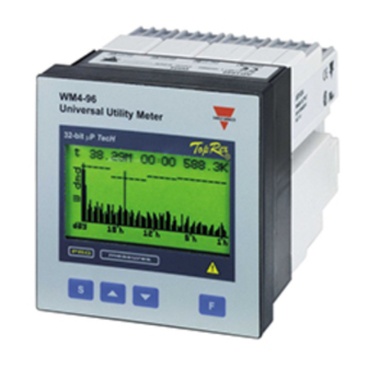
WM4-96: Modular Universal Utility
Meter and Power Analyzer
Harmonic analysis; Energy meters;
Load profile; Plug and play module
system; SMS reception and trans-
mission. These are only a few among
many other functions performed by
your WM4-96. What's more, Carlo
Gavazzi means ISO9001 certification,
a working experience of many
decades and a widespread presence
all over the world. All this because
we want our customers to have the
top service and the top products.
Welcome in the Carlo Gavazzi world
and compliments for your smart
choice. Visit our website and
evaluate our range of products:
www.carlogavazzi.com
Advertisement
Table of Contents

Subscribe to Our Youtube Channel
Related Manuals for CARLO GAVAZZI WM4-96 - PROGRAMMING


Summary of Contents for CARLO GAVAZZI WM4-96 - PROGRAMMING
- Page 1 All this because we want our customers to have the top service and the top products. Welcome in the Carlo Gavazzi world and compliments for your smart choice. Visit our website and evaluate our range of products:...
-
Page 2: Table Of Contents
Index WM4-96 Instruction manual: INDEX CARLO GAVAZZI WM4-96, 32-bit µ-processor based modular universal utili- ty meter and power analyzer FW rev.C.01 TO BEGIN WITH .......5 Front panel description . - Page 3 Index Pass “997”: reset of data memory ..16 Pass “996”: reset of load profiles ..16 LET’S START ....... .17 Main menu .
- Page 4 Index Alarms ......47 Diagnostics ......48 Remote control .
-
Page 5: To Begin With
To begin with HOW TO USE THE SYMBOLS Go to the page where the previous main subject is described. Go to the page where the next main subject is described. Go to the page where the subject written on the top of the current page starts. - Page 6 The easy management and flexibility of WM4-96 is possible thanks to the plug and play modular technology by Carlo Gavazzi and to a powerful 32-bit µProcessor. Also the analogue measuring input module can be adapted to the users’...
-
Page 7: Front Panel Description
To begin with Front panel description Exit from the menu cancel choice you have made. It allows the user to access some func- tions relating to the displayed variables. Scroll to the previous page Access to pro- Scroll to gramming the next settings’... -
Page 8: Displaying Of The Variables
Displaying of the variables Page “00”, Starting page When the instrument is swtched on, the main page of variable displaying is shown. The first page, called page “00”, is the only one configurable by the user who can choose the variables to be dis- played in the 4 displaying areas. -
Page 9: The Display Page
Displaying of the variables How to scroll the various pages To scroll the various pages, use the keys. Pressing the key in any one of the display pages, you access to the programming phase. The key, on the contrary, has various functions depending on the selected page. -
Page 10: Harmonic Analysis
Displaying of the variables Pages from "19" to "24" (from 10 to 11 in single phase mode) Displaying of the harmonic analysis When the instrument is supplied, these pages are not enabled, see page 44 to enable them. The key is active: access to the detailed analysis of the harmonics. - Page 11 Displaying of the variables 0° Generated Harmonics: 270° 90° Imported 180° This angle is displayed only if the measurements are taken in a three-phase system with neutral Pages relating to the energy meters Page "25" (3 without measuring input module) Displaying of the total energy meters key disabled.
-
Page 12: Water Meters
Displaying of the variables Page "27" (5 without measuring input module) Display of Gas and Water meters keys disabled. Depending on the setting, the instru- ment may display one only of the following meter combina- tions: Gas; Gas with Gas in night tariff; Gas and Water. The water and gas meters are managed by the digital inputs. - Page 13 Displaying of the variables Load profile of the Wdmd of the last integration installed power divided period into hour time periods Time of the last integration Installed power Example: con- sumed power integrated in 15 minutes exceeds the installed power Graphic representation of the consumptions Pressing...
- Page 14 Displaying of the variables programmed for that hour time period, the storage time of the Wdmd sample and the relevant value. The data can be scrolled by means of the keys and are relevant to the indication of the arrow that appears on the ascissae axis. To go back to the normal display, press the key again.
- Page 15 Displaying of the variables Only for alarms and diag- Control type: nostics: detection of the alarm (e.g.: A2), diagnostics (e.g.: D1), abnormal condition (ON) or maximum value (MAX), return to the normal condi- minimum value (MIN). tion (OFF) Variable being controlled.
- Page 16 Displaying of the variables Pass "998": display of the stored dmd variables (Only if the RS232 + RTC module is present) The stored dmd variables can be displayed by pressing key in any one of the measuring page (excluded the “load profile”...
- Page 17 Programming It is very important to verify that, every time the configuration of the instrument (modules and/or associated variables, electrical systems, etc.) changes, the setting of the parameters is according to the new configuration. Access to the main menu Press the key to access to the programming menus from the measuring and displaying...
-
Page 18: Change Password
Programming Change Password This function allows you to choose the desired password value (from 0 to 500). Press the key and when the new password value is required, enter the desired value by means of the keys; then press the key to confirm the new value. - Page 19 Programming iff gas metering: to do this the AQ1042 digital inputs + aux mod- ule must be installed in slot A. Choose the “INPUTS” function by means of the keys and press to enter in the sub- menu. Choose the “MEASURE” function by means of the keys;...
- Page 20 Programming kvarh- will be enabled). 3- Once the desired type of meter is confirmed, the instru- ment asks for the number of pulses to be associated to the unit increase (e.g. if you type the value 10 you will need 10 input pulses in order to make the instrument display 1 m 4- A2 INPUT, enabling function of the water metering or of the kvarh- meter (generated kvarh);...
- Page 21 Programming Analogue measuring input module installed (AQ1018 - AQ1019) The instrument carries out only the following measures: W, var, W , var , PF using only the pulses acquired through the digital inputs. The “VA” power is always 0. It’s possible to count and display the measurements of: water and gas, gas and gas night tariff, or Wh- and varh meter.
-
Page 22: Enabling The Tariffs' Remote Control
Programming the counting of the “W” and “var” energies proceed as fol- lows: 5- Choose the C1 INPUT function by the keys (see the description of the selected input function and the weight of the associated pulse under the scrolling window); press to confirm. - Page 23 Programming keys, confirm with . When the ON/OFF win- dow appears select ON by means of the keys to enable the INPUT or OFF to disable it, then confirm your choice by means of the key. Press to go back to the previous menus.
- Page 24 Programming IME PERIODS SELECTION MODE HANNEL SLOT HANNEL SLOT CTION Open Open Tariff 4 Open Close 2 Winter / 3 Summer * Close Open 1 Winter / 2 Summer** Close Close Tariff 4 A (if A2 enabled as GAS): Close = day-time HANNEL SLOT tariff GAS is selected.
- Page 25 Programming System This function allows the user to select the type of electrical system choosing among single phase (1- phase), balanced three-phase plus neutral (3+N phases bal.), unbal- anced three-phase plus neutral (3+N phases unbal.), three phase bal- anced (3 phases bal) and three- phase unbalanced (3 phases unbal).
-
Page 26: Ct Ratio
Programming CT ratio This function allows you to select the value of the CT ratio. Example: if the pri- mary of the CT (current trans- former) being connected is 300A and the secondary is 5A, the CT ratio corresponds to 60 (obtained from the calculation: 300/5). -
Page 27: Display Page
Programming Choose the function VT-PT RATIO by means of ; to con- firm press ; then select the desired value by the 1.2..2.1 keys and confirm with . To reset your choice and go back to the main menu, press Changing the VT ratio, all the MIN/MAX values, all events and partial energy meters are reset. -
Page 28: Min Max Values
Programming MIN MAX VALUES This function allows the user to associate some variables to the automatic recording of maximum values (from MAX1 to MAX12) and minimum values (from MIN1 to MIN8). To use this function, proceed as follows: select the MIN MAX VALUES function from the main menu using the keys and confirm it with... - Page 29 Programming EVENTS SELEC. This function allows the user to enable the events for data logging: • MAX (logging of up to 12 differ- ent variables MAX1 to MAX12), see also: MIN MAX VALUES; • MIN (logging of up to 8 different vari- ables MIN1 to MIN8), see also MIN MAX VALUES;...
- Page 30 Programming Data logging This function enables the logging of the required variables in the data logging. 1) Choose the function DATA LOG- GING by means of the keys, press to confirm; 2) select “DMD VARIABLES” by means of the keys and confirm with 3) the display shows the window with the list of the available DMD variables:...
- Page 31 Programming DMD/AVG calcul. This function allows you to select calculation method of W-VA-PF. To enter these functions, select “DMD/AVG CALCUL” from the main menu using the keys and confirm the selection with . You can thus enter the DMD/AVG CALCUL. method: choose between the FIXED or 1.2..
- Page 32 Programming updates its value at first after 15 minutes and afterwards every minute generating a window whose width corre- sponds to “15 minutes” and shifts by units of 1 minute. On the following page you can see the diagram that shows the two operating methods.
- Page 33 Programming FIXED AVERAGE CALCULATION Where: Pmax is the maximum measured power, Pc is the contractual power, t1 is the selected average period FLOAT AVERAGE CALCULATION DMD/AVG calculation Holidays period...
- Page 34 Counters Management Access to the Counters menu This function allows you to choose the type of management of the energy meters. Select “COUNTERS” from the main menu by means of the keys; confirm with enter the specific sub-menu. Counters SINGLE TARIFF Management This function allows you to choose the energy meters according...
- Page 35 Counters Management 1-press : the first box (trf=tar- iff) is highlighted; 2-press again: the TARIFF box will appear on the lower part of the display; now you can choose the tariff (from 1 to 4), e.g.: “1” by means of the keys;...
- Page 36 Counters Management ters; use the key to move from the left to the right and the key to move from the right to the left. 8- press to exit the programming of the parameters of the relevant row (no boxes are to be highlighted); 9-press to select one of the other programming lines;...
- Page 37 Counters Management hour of the previous time period; d) the daily loop is closed by setting 24:00 as last hour of the last time period (to follow this procedure see step 4 on page 35), confirm the setting by pressing to go back to the TARIFF SELECTION menu (“COUNTERS”...
- Page 38 Counters Management 15-press the key again to open the box where the day is to be set, 16-use the keys to select the desired day (from 1 to 31 depending on the previously selected month); 17-press the key to confirm the selection and move to th next parameter.
- Page 39 Counters Management MULTI TARIFF This function allows the management of the counters according to many periods per day and three periods per year: WINTER, SUMMER and HOLIDAY. To program the parameters relat- ing to the winter season, simply follow the same procedure (holi- days) described on page 37 from Step 11 to Step 17.
- Page 40 Counters Management DUAL TARIFF management trf1 trf1 WHOLE YEAR WHOLE YEAR start OO:OO O8:OO O8:OO 2O:OO 2O:OO OO:OO TARIFF trf2 As you can see on the figure above, there’s a daily division into three periods with two different tariffs. MULTI TARIFF management WINTER start trf1...
- Page 41 Counters Management Installed power This function allows the user to set the maximum installed tar- iff power (as per contract). The set power is associated to the desired tariff (t1-t2-t3-t4) and it’s displayed in the load profile graph (see also load profiles on page 12).
- Page 42 Counters Management Reset of the Energy Counters The “RESET” menu allows you to reset the energy counters. Press to enter the menu and then use the keys to select the desired type of reset. Press to enter the menu, then the instrument displays the following message: PAY ATTENTION, ALL THE METERS WILL BE RESET!! WILL YOU CONTINUE?
- Page 43 Counters Management Gas Counters Reset The GAS RESET menu allows the user to reset the gas counters. Select GAS RESET by means of keys and con- firm with . The instrument displays the following mes- sage: PAY ATTENTION, ALL THE GAS COUNTERS WILL BE RESET! WILL YOU CONTINUE? To end the RESET procedure press ;...
- Page 44 Outputs / Other settings Harmonics analysis This function enables the display of the windows relating to the harmonics analysis. Press to enter the HARMONICS menu: then, use keys to select the phase where you want the harmonic analysis to be enabled. key allows the user to enable (ON) or disable (OFF) the displaying (the function is cyclical: ON-OFF-ON).
-
Page 45: Digital Outputs
Outputs / Other settings The EURO/USA function allows the user to display the date and time according to the EUROPEAN (EURO, date: day/month/year; time: 24 hours) or AMERICAN (USA, date: month/day/year; time: 12 hours / AM and PM) format. Digital Outputs This function enables the user to connect the type of digi- tal output to the slot at the... - Page 46 Outputs / Other settings The meaning of the symbols on the display is the following: OUT C0 (1): digital output SLOT C0, channel 1 OUT C1 (2): digital output SLOT C1, channel 2 OUT D0 (3): digital output SLOT D0, channel 3 OUT D1 (4): digital output SLOT D1, channel 4 Pulse output This function allows the user...
-
Page 47: Alarms
Outputs / Other settings type. Confirm with and go back to the digital output menu. To reset the choices and go back to the main menu, press . The multiplyer of the measuring unit (kW, MW) automatically changes according to the CT or VT ratio set by the user. - Page 48 Outputs / Other settings •Type: type of alarm: up alarm (MAX); down alarm (MIN); up alarm with latch (UP L): in this case the reset of the output can only be manual; down alarm with latch (D.L.): in this case the reset of the output can only be manual; down alarm with disabling at power ON (D.DO).
-
Page 49: Rs232
Outputs / Other settings Remote control This function enables the control of the digital outputs by means of the RS485/RS232 communication port instead of using the instrument’s alarm. The outputs can be activated by a PC or PLC by sending special commands. Select the REMOTE CONTR. -
Page 50: Modem
Outputs / Other settings Modem The instrument communi- cates with a remote PC by an analogue modem. Select MODEM from the RS232 sub-menu by means of the keys and confirm with . The window with the modem settings appears: 1- PHONE NUMBER: select it using the keys and confirm it with... - Page 51 Outputs / Other settings managed for each call. The subsequent calls are managed by priority: if the first phone number is engaged, the instru- ment calls the second and so on; when a phone number answers the call, then the alarm message is forwarded and the calls are finished.
- Page 52 Outputs / Other settings keys and confirm it by . Then, select the desired numeric code by means of the keys and confirm with 3- ALARMS: it enables the transmission of SMS alarm mes- sages to GSM mobile phones when one of the selected alarms changes status (activation or deactivation).
- Page 53 Outputs / Other settings EQUIRED EQUEST EPLY NFORMATION WM4.xxx.VN WM4.xxx:[info] WM4.xxx.VL WM4.xxx:[info] L1-2 L2-3 L3-1 WM4.xxx.A WM4.xxx:[info] WM4.xxx.W WM4.xxx:[info] , VA , VA WM4.xxx.VA WM4.xxx:[info] , var , var , var WM4.xxx.VAR WM4.xxx:[info] , PF , PF , PF WMA.xxx.PF WM4.xxx:[info] , VA , var...
-
Page 54: Rs485
Outputs / Other settings RS 485 Select SERIAL OUTPUT from the main menu, then select RS485 by means of the keys and confirm with Select the parameter to be set from the available sub-menus with the keys and confirm it with . -
Page 55: Language
Outputs / Other settings • COEFFICIENT, to set the filtering coefficient of the instantaneous measurements. Increasing the value, also the sta- bility and the settling time of the measurements are increased. Once one of the three parameters has been selected, set the desired value by means of the keys and confirm it with . - Page 56 Useful Info The variables measured by the instrument are correct if the inputs have been connected according to the right polarities (see figure below). Should the connec- ction not be conforming to the right polarities, meas- uring and retransmission errors may occur, both due to the wrong direction of the current flowing in the primary/secondary of the ammeter transformer being connected.
- Page 57 Useful Info higher value of this coefficient results in a higher settling time, that means a higher stability. The best result is generally obtained by setting the filtering coefficient at a value equal to at least 10 times the value of the range parameter. Considering the example above: 1.5*10=15.
- Page 58 Useful Info No 1st variable 2nd variable 3rd variable 4th variable var L1 var L2 var L3 VA L1 VA L2 VA L3 PF L1 PF L3 PF L4 V L1 A L1 PF L1 W L1 V L2 A L2 PF L2 W L2 V L3...
- Page 59 Useful Info List of the available variables: The availability of the variables depends on the type of electrical system being selected. Installation Preliminary operations Before switching the instrument on, make sure that the power supply voltage corresponds to what is shown on the side label of the relevant module.
- Page 60 Installation ceived to be mounted in one slot only. To know in which slot every module is to be mounted, refer to the figure on page 62. For a correct mounting of the instrument, insert the modules in the relevant slots, then, at the end, enter the central mod- ule, which can be a blind type module or an RS232 com- munication module.
- Page 61 Installation Overall dimensions and panel cut-out Mounting Insert the instrument (holding its front) and fasten it (from the back) by fixing the two lateral brackets (1) (supplied with the instrument) to the approprite location (2), using the two screws (3) supplied with the instrument.
-
Page 62: Available Modules
Installation Position of the slots and relevant modules Available modules Relay digital output modules AO1058 AO1035 Single relay Dual relay output output What is ASY? Power supply modules... - Page 63 Installation DESCRIPTION D PU PS IM RS485 Serial output RS232 Serial output + RTC+Data Memory Single relay output Single open collector output Dual relay output Dual open collector output Four open collector output 3 digital inputs 3 digital inputs +AUX Power supply Inputs Open collector digital output modules...
-
Page 64: Power Supply Modules
Installation Digital input modules AQ1038 AQ1042 3 digital 3 digital inputs+ inputs aux power supply Serial output modules AR1041 RS232 Interface + RTC + AR1034 Data memory RS485 Interface Power supply modules AP1021 AP1020 18-60 VAC/DC 90-260 VAC/DC Power supply Power supply List of the variables Serial output connections... -
Page 65: Optional Modules Connection
Installation Optional modules connection Digital inputs Connection by means of NPN transistor. AQ1042 digital input module Connection by means of NPN transistor. AQ1042 digital input module. Connection by means of contacts. AQ1042 digital input module. Connection by means of contacts. AQ1038 digital input module. -
Page 66: Relay Output
Installation Relay output Open collector outputs This diagram is valid also for the open collector modules with a lower number of outputs. The value of the load resist- ances (Rc) must be cho- sen so that the short-cir- cuit current is lower than 100mA;... - Page 67 Installation 2-wire connection. Additional devices provided with RS485 (that is RS 1, 2, 3 ...N) are connected in parallel. The termination of the serial output is carried out only on the last instrument of the network, by means of a jumper between (Rx+) and (T). We rec- ommend you to use the 4-wire connection: by means of the serial port the data are exchanged faster.
- Page 68 Electrical connections Electrical connection diagrams three-phase connection, balanced load 3/4-wire Direct connection Direct connection (3-wire system) (3-wire system) CT and VT connection CT and VT connection (3-wire system) (4-wire system) Position of the modules ARON connection...
- Page 69 Electrical connections Three-phase, 4 wires, balanced load CT connection CT and VT connection (4-wire system) (4-wire system) Three-phase, 4 wires, Unbalanced load Direct connection CT connection (4-wire system) (4-wire system) Serial output connection Technical features...
- Page 70 Electrical connections 3/4-wire, three-phase connection, Balanced load CT and VT connection CT and VT connection (4-wire system) (4-wire system) 3-phase / 3-wire ARON connection, Unbalanced load CT connection CT and VT connection (3-wire system) ARON (3-wire system) ARON Optional module connection Technical features...
-
Page 71: Single Phase Connection
Electrical connections 3-phase / 3-wires conn. Single-phase connection 3-CT and 3 VT connection Direct connection (3-wire system) Single-phase connection CT connection CT and VT connection 4-wire connection RS232... -
Page 72: Technical Features
Technical features Input features Number of analogue inputs Current: 1 (single-phase; system: 3). 4 (three-phase; system: 3) Voltage: 1 (single-phase; system: 3). 4 (three-phase; system: 3). Digital inputs AQ1038 Number of inputs: 3 (free of voltage). Use: synchronization of W-VA dmd measurements Interfacing: GMC/GME. - Page 73 Technical features Voltage: range AV5: ±0.5% rdg (48 to 300V range AV7: ±0.5% rdg (80 to 480V ) included the following influences: frequency, output load power supply. Frequency: ±0.1% rdg (40 to 440 Hz). Active power (@ 25°C ± 5°C, R.H. 60%): ±0.5% (rdg + fs) (PF 0.5 L/C, 0.1 to 1.2 In, range AV5).
- Page 74 Technical features Sampling: 6400 samples/s @ 50Hz. Display: graphic back-lighted LCD (128x64 dots). Selectable read-out for the instantaneous variables: 4x4 digit or 4x3 digit. Total energies: 4x9 digit. Partials: 4x6 digit. Max. and min. indication: Max. 9999 (999999999). Min. -9999 (–999999999). Measurements Curent, voltage, power, energy, power factor, frequency, har- monic distortion (see display specs).
- Page 75 Technical features Output specifications RS422/RS485 (on request) Bidirectional multidrop (static and dynamic variables) Connections: 2 or 4 wires, max. distance 1200m, termina- tion directly on the module. Addresses: from 1 to 255, key-pad programmable. Protocol: RTU MODBUS/JBUS. Data (bidirectional) dynamics (reading only): all displayable variables.
- Page 76 Technical features GSM modem for the transmission of SMS messages: of data logging and energy meters. The alarms can be sent also automatically while the variables can be recalled by means of special SMS question codes (see “How to use the SMS”...
- Page 77 Technical features Alarm outputs (on request) Number of set-points: up to 4, independent. Alarm type: up alarm, down alarm, with or without latch, phase asymmetry, phase loss, neutral loss. Monitoring of the variables: all the variables listed in the paragraph “List of the connectable variables”. Set-point adjustment: 0 to 100% of the electrical scale.
- Page 78 Technical features power quality analysis (LV or MV/HV connection). Indirect energy and power measurements by means of watt-hour meters (LV or MV/HV connection); Direct measurements for the instantaneous variables (LV connection) and indirect measurements for the energy variables (LV or MV/HV). It’s possible to add the management of gas and water metering to all of these working modes.
- Page 79 Technical features Data management type Type: FIFO. Memory size: 2Mb. Battery life: 10 years Data logger function The data are stored at time intervals from 1 to 60 min.; up to 8 instantaneous variables can be selected. Historical data storing time: 3 weeks with storing time interval of 1 min.
- Page 80 Technical features Stored events: 240 pages, display by means of pass- word. Data logger: display of the data by means of pass- word with reset function of the relevant memory section. Load profile: 3 pages, daily, weekly and monthly graphic display.
- Page 81 Technical features General specifications Operating temperature: 0 to +50°C (32 to 122°F) (R.H.< 90% non-condensing). Storage temperature: -10 to +60°C (14 to 140°F) (R.H. < 90% non-condensing). Insulation reference voltage: 300 V to ground (AV5 input). Insulation: 4000 V between all inputs / outputs to ground. Dielectric strength: 4000 V for 1 minute Noise rejection: CMRR 100 dB, 48 to 62 Hz.
- Page 82 Technical features Harmonic analysis Analysis principle: FFT. Harmonic measurement: current, up to the 50 th harmonic; voltage, up to the 50 th harmonic. Type of harmonics: THD (V 1) THD odd (V 1) THD even (V The same is for the other phases: L2, L3.
- Page 83 Technical features Time period management (energy, water and gas metering) Time periods: Energy. Selectable: single time, dual time and multi-time. Single time: Energy, water, gas Number of meters: total: 4 (9-digit) (no partial meters) Dual time: Energy, gas Number of meters: total: 4 (9-digit); partial: 8 (6-digit). Time periods: 2, programmable within 24 hours.
- Page 84 User’s page Name: ....Surname: ... . . Company name: ....... . WM4-96 Serial number: .
Need help?
Do you have a question about the WM4-96 - PROGRAMMING and is the answer not in the manual?
Questions and answers