
Related Manuals for CARLO GAVAZZI UDM 35 - PROGRAMMING


Summary of Contents for CARLO GAVAZZI UDM 35 - PROGRAMMING
- Page 1 CARLO GAVAZZI A u t o m a t i o n C o m p o n e n t s UDM 35/40 Digital Panel Meter Programming Guide...
-
Page 2: Table Of Contents
UDM 35/40 PANEL METER USER MANUAL Index Description Programming Fundamentals Access to Programming Mode/Password Protection Programming 5-18 Inputs Temperature Compensation Display Configuration Scaling the Inputs Decimal Point Position Display Span Configuration Linearization 11-12 Alarm Set Point Configuration 12-16 Digital Filtering 16-17 Analog Output/Retransmission of Display Value 17-18... -
Page 3: Description
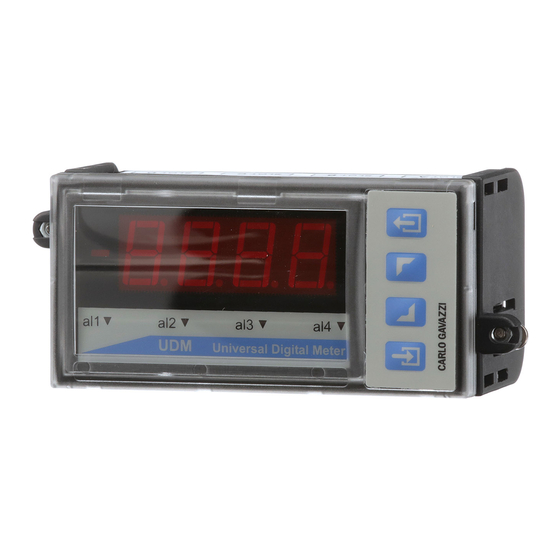
UDM 35/40 PANEL METER USER MANUAL UDM Description The UDM 35/40 series is a universal Digital Panel Meter that has been developed to meet the most advanced application requirements. The UDM 35 offers: • Quick assembly and maintenance using plug & play modules •... -
Page 4: Programming Fundamentals
UDM 35/40 PANEL METER USER MANUAL UDM 35/40 Programming Fundamentals There are no jumpers to consider when programming the UDM 35/40. The programming mode allows the user to define all of the instrument’s parameters. Shown below are a description and the UDMxx display symbol for each basic parameter grouping: •... - Page 5 UDM 35/40 PANEL METER USER MANUAL Access to Programming Mode Press and hold for 2 seconds. Display will indicate (password). Within 2 seconds, four zeros “0000” will be displayed as follow: This is your prompt to enter your password. Each individual digit is selected from left to right by toggling the key.
-
Page 6: Programming
UDM 35/40 PANEL METER USER MANUAL Programming the Input Modules Press and hold for 2 seconds. Display will indicate PASS (password). Within 2 seconds, four zeros “0000” will be displayed. This is your prompt to enter your password. If zero “0000” is your password, simply press to confirm. -
Page 7: Temperature Compensation
UDM 35/40 PANEL METER USER MANUAL LSX and HSX input modules offer True RMS (trnS) or DC measurement (dC). Use keys to make selection. Press Press keys to select Input signal integration time value (intt). If all zeros “0000” is selected, “Auto” will be displayed and the value will be automatically calculated from 100ms –... - Page 8 UDM 35/40 PANEL METER USER MANUAL Press key to select Auto (Auto). Press to confirm. . Press advance to next program step sequence. Manual compensation should only be used in special applications. Consult factory. Configuring the Display (diSP) UDM35 only UDM 35 (BD35) base unit displays may be configured as 3 ½...
-
Page 9: Scaling The Inputs
UDM 35/40 PANEL METER USER MANUAL Scaling the Inputs When is displayed, access is available for configuring the electrical input range, the decimal point position and display span as follows: Electrical Input Range (HiE and LoE) Allows the operator to define an electrical input range different from the standard range setup at the “inP”... -
Page 10: Decimal Point Position
UDM 35/40 PANEL METER USER MANUAL Decimal Point Position (dP) The decimal point position is relative to the Display Value, which will be discussed next. When “dP” is displayed, press . Using the keys, select the decimal point position and press to confirm and advance to next step, “Lod”... -
Page 11: Linearization
UDM 35/40 PANEL METER USER MANUAL Linearization Introduction When is displayed, a signal from a non-linear transducer-sensor may be modified by setting the input (in. 01 – in. 16) and output (ou. 01 – ou.16) linearization points so that the accuracy of the displayed value is maximized. - Page 12 UDM 35/40 PANEL METER USER MANUAL Navigating & Programming within the Linearization Menu appears, press followed by keys to choose to ignore or enable linearization . Press to confirm your choice and advance to next step. If you chose YES, you will be prompted to enter the number of Linearization Points, using the escape button...
- Page 13 UDM 35/40 PANEL METER USER MANUAL Hysteresis selection Off-Delay Value (0-255s) On-Delay Value (0-255s) Relay Selection (normally energized or de-energized) Alarm Type (off, down, up, up with latch, down with latch) Color of display during alarm (red, orange, green, none) If “none”...
- Page 14 UDM 35/40 PANEL METER USER MANUAL Navigating through this program sequence Minimum Set-Point The lowest value, below which, it is not possible to program a set-point. When is first displayed, you have reached the Set-point program sequence. Press to enter program. The first parameter, Minimum Set-point Limit, will be displayed.
- Page 15 UDM 35/40 PANEL METER USER MANUAL Hysteresis The point at which an active alarm output must revert to for the alarm output to turn off. Example: If an “up” alarm set point is “10.5”, and you want to have the alarm reset at “10.3”, then the Hysteresis value to set in the program must be “.2”, not 10.3.
-
Page 16: Digital Filtering
UDM 35/40 PANEL METER USER MANUAL Configuring the Display Color for Alarm Event (UDM40/BD40 only) When is displayed, the color of the display may be set to be RED, ORANGE, or GREEN during the alarm event. Selecting NONE results in the basic display color being used during alarm event. - Page 17 UDM 35/40 PANEL METER USER MANUAL The second filter parameter is . It represents the filtering coefficient. The higher the value of Fil.C, the smoother the curve of the displayed value. There is no theoretical rule to define this parameter, but it is suggested to start with the same value of the Fil.S coefficient and then increase it until the desired stability is reached.
-
Page 18: Serial Port Output
UDM 35/40 PANEL METER USER MANUAL Programming example: Retransmit a 4-20mA signal proportional to the following displayed values: Lo.D = 0 and Hi.D = 18. When is displayed, the Analog Output program may be addressed. Press to enter sequence. is displayed. Press to toggle to the first position. - Page 19 CONVERTING CELSIUS TO FAHRENHEIT The UDM35/40 digital panel meters use the Celsius temperature scale. However, the displayed value can easily be scaled to indicate Fahrenheit values by using the following guidelines: The LoE and HiE are always expressed as Celsius values. To display Fahrenheit values, manually convert the LoD to a Fahrenheit value and then convert the HiD to a Fahrenheit value.
-
Page 20: External Command Function
UDM 35/40 PANEL METER USER MANUAL External Command Function When is displayed, the user may elect to dedicate a Command signal (contact closure) from the input module, terminals 6 & 7, to perform one of the following: HOLD Function Disable-Keypad Reset latch Alarms Press to select Command sequence. - Page 21 UDMsoft Programming The software is menu driven. Just fill-in-the-blanks with your parameters. There is little explanation required. It is actually a simple process. Any confusion and concern that has surfaced has surrounded the issue of setup with the PC/laptop. The following segment is meant to clarify how to establish solid communication between UDM and PC.
- Page 22 UDM 35/40 PANEL METER USER MANUAL Links: Resources & Data Sheets UDM 35 Datasheet https://www.gavazzionline.com/images/UDM35DS5ENG0404.pdf UDM 40 Datasheet https://www.gavazzionline.com/images/UDM40DS5ENG0404.pdf UDM3540 Program Flow Chart UDM3540 Input-Output Modules UDM3540 FAQ (English) Panel Meter Selection Guide: https://www.gavazzionline.com/usameters.htm UDMSoft Downloads: https://www.gavazzionline.com/usadwnload.htm Supplemental Announcements: Connecting Programming Cable to PC, use with UDMSoft: Item # UCABLE...
Need help?
Do you have a question about the UDM 35 - PROGRAMMING and is the answer not in the manual?
Questions and answers