
Related Manuals for CARLO GAVAZZI WM50


Summary of Contents for CARLO GAVAZZI WM50
- Page 1 WM50 Multichannel power analyzer for single, two and three-phase systems INSTRUCTION MANUAL...
-
Page 2: Table Of Contents
TCD12 identification Essential information Managed measurements Configure the system Introduction Configure WM50 Main line measurements Configuration mode Channel and load measurement (TCD12) Configuration requirements via UCS WM50 - Instruction manual | 2017-10 | © 2017 | CARLO GAVAZZI Controls SpA... - Page 3 Problems during settings Cleaning Responsibility for disposal Features WM50 common specifications General features Environmental specifications Input and output insulation Main unit specifications Electrical specifications Power supply WM50 - Instruction manual | 2017-10 | © 2017 | CARLO GAVAZZI Controls SpA...
- Page 4 Protection may be impaired if the instrument is used in a manner not specified by the manufacturer. Service and warranty In the event of malfunction, fault, requests for information or to purchase accessory modules, contact the CARLO GAVAZZI branch or distributor in your country.
-
Page 5: Wm50 And Tcd12
96 single-phase loads or any combination of single and three-phase loads or two and single-phase loads for a maximum of 96 channels. The system can be set up, measurements viewed and up to 16 alarms managed from WM50 and UCS. Main unit functions can be expanded with a maximum of two of the following available modules: digital input/output module, analog input module and communication module. -
Page 6: Components
M C ETH TCD12 12-channel current sensor. Measures main electrical variables on the single channels and loads and transmits them to WM50. A maximum of eight TCD12s can be connected in series on two TCD buses to each WM50 via TCD12WS cables. -
Page 7: Main Unit - Rear
All blinking: TCD12 configuration inconsistent with set electrical system. Note: for details on the type of inconsistency, see the Warning page in “Settings menu” on page 19. Alarm 13, 14, 15, 16 status WM50 - Instruction manual | 2017-10 | © 2017 | CARLO GAVAZZI Controls SpA... -
Page 8: Accessory Modules
Internal local bus port for communications with main unit or other accessory module External local bus port for communication with communication module. Not included in communication modules. WM50 - Instruction manual | 2017-10 | © 2017 | CARLO GAVAZZI Controls SpA... -
Page 9: Tcd12
Blinking: TCD12 not configured or not consistent with the set configuration Power supply status Off: no power supply On: powered Blinking: TCD12 identification function on Note: for problem solutions, see “Troubleshooting” on page 38. WM50 - Instruction manual | 2017-10 | © 2017 | CARLO GAVAZZI Controls SpA... -
Page 10: Tcd12Ws
UCS (Universal Configuration Software) UCS is available in desktop and mobile versions. It can connect to WM50 via accessory communication modules (Modbus TCP/IP or Modbus RTU protocol) or via OptoProg (via USB or Bluetooth). The following is possible with UCS: •... -
Page 11: Wm50 Use
Page identification number Page title, see “Settings menu” on page 19 Warning and information area, see “Information and warnings” on page 12 Current value/option Possible value/option range WM50 - Instruction manual | 2017-10 | © 2017 | CARLO GAVAZZI Controls SpA... -
Page 12: Reset Menu Display
Feedback after pressing a button Serial or optical communication status (receiving/ Voltage connection error (inverted sequence) transmitting) Hot water totalizer (m Cold water totalizer (m Hot water energy totalizer (kWh) WM50 - Instruction manual | 2017-10 | © 2017 | CARLO GAVAZZI Controls SpA... -
Page 13: Working With Wm50
View the measurement page set as the Home page. Scroll minimum, maximum, average (dmd) and maximum among averages values (max dmd) for variables in displayed page. WM50 - Instruction manual | 2017-10 | © 2017 | CARLO GAVAZZI Controls SpA... -
Page 14: Working With The Settings Menu
Exit menu? page Note *: for details, see “Setting numeric parameters” on page 16. Common operations Operation Button Confirm operation View the previous/next page Cancel operation WM50 - Instruction manual | 2017-10 | © 2017 | CARLO GAVAZZI Controls SpA... -
Page 15: Setting A Parameter
When setting a parameter, E indicates the edited row, the blinking dash the number. Example procedure: how to set Filter co=25 and save changes. Note: the initial procedure status is the Filter co page in the settings menu. WM50 - Instruction manual | 2017-10 | © 2017 | CARLO GAVAZZI Controls SpA... -
Page 16: Setting Numeric Parameters
To save settings, scroll the settings menu pages until the End page is displayed and press CAUTION! Changes are not saved if you exit the settings menu in another way. WM50 - Instruction manual | 2017-10 | © 2017 | CARLO GAVAZZI Controls SpA... -
Page 17: Menu Description
∑ ∑ Phase 1 reactive power Phase 1 power factor Phase 2 reactive power Phase 2 power factor Phase 3 reactive power Phase 3 power factor WM50 - Instruction manual | 2017-10 | © 2017 | CARLO GAVAZZI Controls SpA... - Page 18 Even THD of phase 2 current THD % Even THD of phase 3 current M A TPN module page Displayed Description measurements Matp Analog input °C/°F Temperature WM50 - Instruction manual | 2017-10 | © 2017 | CARLO GAVAZZI Controls SpA...
-
Page 19: Settings Menu
Hea ng Year Trip Month Hour Minute Second Note: for the description of all settings, possible and default values, see “Settings from WM50” on page 31. WM50 - Instruction manual | 2017-10 | © 2017 | CARLO GAVAZZI Controls SpA... -
Page 20: Information Menu
Modbus address Baud rate of RS485/RS232 port IP address IP address Date Date time Hour Data events Number of events recorded in the main unit event database. WM50 - Instruction manual | 2017-10 | © 2017 | CARLO GAVAZZI Controls SpA... -
Page 21: Essential Information
WM50 calculates and displays both main line and single channel and load measurements. All measurements are displayed by UCS or via Modbus communications (Carlo Gavazzi VMU-C monitoring system or other data acquisition system). Main line measurements are also available on screen. -
Page 22: Measurement Management
Essential information Measurement management Measurement error If a measurement is not available or out of range, it is displayed as "EEEE" on WM50 display and as "--" on UCS. See “Troubleshooting” on page 38. Average value calculation (dmd) The system calculates the average value of electrical variables in a set integration interval (15 min by default). The average value will not be available if the variable measurement is out of range. -
Page 23: Voltage Asymmetry Calculation
Intervention range = 2 Measured value Measurements displayed with coefficient = 2 Measurements displayed with coefficient = 10 From WM50: See “Settings from WM50” on page 31, sub-menu Filter. WM50 - Instruction manual | 2017-10 | © 2017 | CARLO GAVAZZI Controls SpA... -
Page 24: Alarms
The alarm is activated when the monitored variable exceeds the Set 1 value for a time equal to the activation delay (Delay) and is deactivated when it drops under Set 2 (if the latch function is not on). Set 1 Set 2 Delay WM50 - Instruction manual | 2017-10 | © 2017 | CARLO GAVAZZI Controls SpA... -
Page 25: Start-Up Condition Management
If several alarms are associated with an output, the output will only activate if all the alarms set with AND logic are active or if at least one of the alarms set with OR logic is active. WM50 - Instruction manual | 2017-10 | © 2017 | CARLO GAVAZZI Controls SpA... -
Page 26: Setting Alarms
Accessory modules Enabling accessory modules Accessory modules are automatically recognized by WM50. They only need to be manually set if configuring the system from UCS in offline mode. Note: by default, the M C 485 232 communication module is always enabled even if not actually connected. -
Page 27: Digital Outputs
Pulse transmission output on active or reactive, imported or exported energy consumption. • Energy type • Pulse weight Only from WM50, a pulse transmission test can be run, see “Running a pulse transmission • Enable of transmission test test” on page 34. -
Page 28: Disabling Tariff Management
Essential information Disabling tariff management Set tariff management as disabled or enter 6 in the 143Fh register. From WM50: See “Settings menu” on page 19, sub-menu Tariff and Dig in x. Database Introduction Database can be exported to .xls file and databases and single variables, events and values to be saved can be enabled/disabled from UCS. -
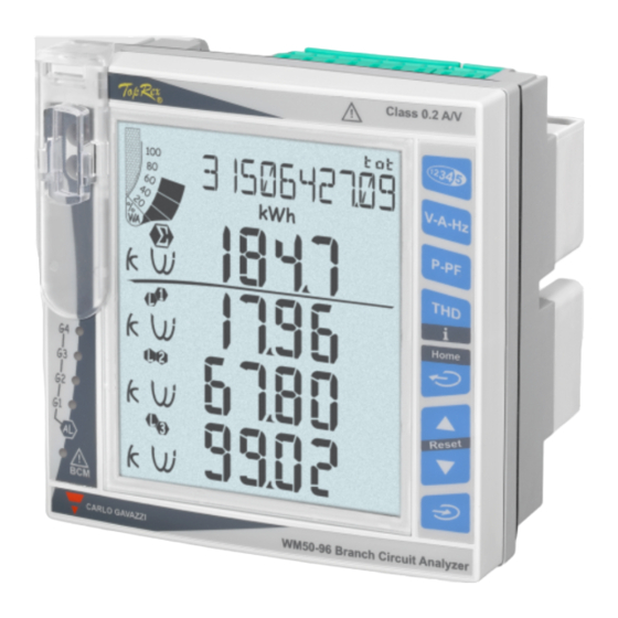
Page 29: Lcd Display
TCD12 TCD12 identification TCD12 configured and connected to WM50 is identified by the system via the combination of its three features: • serial number (on the top of the sensor) • physical position on the TCD bus (i.e.: A1 for TCD A bus TCD12 closest to WM50) •... -
Page 30: Configure The System
To learn more about settings pages, see “Settings from WM50” on page 31. Configuring WM50 via PC or smartphone Note: communication parameters may need to be set via touch keypad to communicate with WM50. 1. Meet all the requirements indicated in “Configuration requirements via UCS” before. -
Page 31: Settings From Wm50
OptoProg skip to the next step 3. Start UCS and connect to WM50 via automatic scan or by manually setting correct communication parameters. 4. Open the settings section, set parameters and save changes. - Page 32 Power value for test From 0.001 W to 9999 MW Tariff Tariff management none: disabled Cloc: via internal calendar and clock Inp: via digital inputs Remo: via Modbus command WM50 - Instruction manual | 2017-10 | © 2017 | CARLO GAVAZZI Controls SpA...
- Page 33 Yes: resets values/ No: no action Reset Resets maximum values Reset DMD Resets DMD values Reset DMax Resets Max DMD values Reset MIN Resets minimum values WM50 - Instruction manual | 2017-10 | © 2017 | CARLO GAVAZZI Controls SpA...
-
Page 34: Accessory Modules Settings
4. Select the layout that represents the physical TCD12 positions. 5. Select TCD12s connected to port A (TCD A bus) and those connected to port B (TCD B bus) in the order they are connected to WM50 (i.e.: A1 for TCD A bus TCD12 closest to WM50). -
Page 35: Moving A Tcd12
• check/assign the correct phase to each channel. • optional. Create load groups. 8. Save changes. 9. If necessary, download the configuration on WM50 and check settings, see “TCD12 LED status” on page 9 and “Troubleshooting” on page 38. Moving a TCD12 If TCD12 position on the TCD bus changes, the system recognizes it: from UCS, view the warning on the involved TCD12. -
Page 36: Other Operations
Reset energy meters and totalizers Energy meters for the main line and totalizers can be reset from both WM50 and UCS. TCD12 energy meters can only be reset from UCS. From WM50: See “Settings from WM50” on page 31, sub-menu Meters. -
Page 37: Communicating With Other Devices
2. Set network parameters via WM50 keypad or from USC mobile connected with OptoProg. 3. Connect WM50 to the master via Ethernet cable to the LAN or directly (point to point connection). 4. Create communications via mater (PC, VMU-C, PLC, etc.) connected to the same LAN or connected point to point. -
Page 38: Maintenance And Disposal
Maintenance and disposal Troubleshooting Note: in the event of malfunction or fault, contact the CARLO GAVAZZI branch or distributor in your country. Measurement problems Problem Cause Possible solution 'EEEE' (on WM50) or "--" (on UCS) appears The current transformer settings are not correct... -
Page 39: Led
The product must be disposed of at the relative recycling centers specified by the government or local public authorities. Correct disposal and recycling will contribute to the prevention of potentially harmful consequences to the environment and persons. WM50 - Instruction manual | 2017-10 | © 2017 | CARLO GAVAZZI Controls SpA... -
Page 40: Features
For 500 ms: 2 Un max Auxiliary power supply From 100 to 277 V ac/dc ± 10% Input impedance >1.6 MΩ Consumption ≤20 VA (approx), 9 W(dc) Frequency 50/60 Hz WM50 - Instruction manual | 2017-10 | © 2017 | CARLO GAVAZZI Controls SpA... -
Page 41: Main Line Measurement Precision (Main Unit)
("pulse" (dmd) function only) • Pulse type and pulse weight ("pulse counting" function only) Configuration mode Via keypad or UCS Configuration mode Via keypad or UCS WM50 - Instruction manual | 2017-10 | © 2017 | CARLO GAVAZZI Controls SpA... -
Page 42: M F I6 R4 Module Features
Via keypad or UCS Configuration mode Via keypad or UCS NOTE: the RS485 and RS232 ports are alternative. Meaning Communication status: • Yellow: receiving • Green: transmitting WM50 - Instruction manual | 2017-10 | © 2017 | CARLO GAVAZZI Controls SpA... -
Page 43: M C Eth Module
A 1 A input for neutral current, a temperature probe input, a 20 mA analog input M C 485232 Communication Modbus RTU communication on RS485/RS232 M C ETH Modbus TCP/IP communication on Ethernet WM50 - Instruction manual | 2017-10 | © 2017 | CARLO GAVAZZI Controls SpA... -
Page 44: Tcd12 Part Number
No option included TCD12WS cable part number TCD12WSS2TI Model Length: 030: 30 cm 050: 50 cm 100: 100 cm 200: 200 cm 300: 300 cm 500: 500 cm WM50 - Instruction manual | 2017-10 | © 2017 | CARLO GAVAZZI Controls SpA... - Page 46 CARLO GAVAZZI Controls SpA via Safforze, 8 32100 Belluno (BL) Italy www.gavazziautomation.com info@gavazzi-automation.com info: +39 0437 355811 fax: +39 0437 355880 WM50 - Instruction manual 2017-10 | Copyright © 2017...
Need help?
Do you have a question about the WM50 and is the answer not in the manual?
Questions and answers