
Subscribe to Our Youtube Channel
Related Manuals for Omtech SH-G570


Summary of Contents for Omtech SH-G570
- Page 1 V20250106 SH-G570 | 100W | CO Cabinet Laser Engraver User Manual Read Carefully Before Use Keep for Future Reference...
- Page 2 BEAMING WITH POSSIBILITIES! Thank you for choosing our laser equipment. Your CO ₂ laser engraving machine is intended for personal and professional use. When used under these instructions, it falls under the category of a CLASS 1 laser product. But it includes a CLASS 4 laser and some components remain EXTREMELY dangerous under improper and/or non- intended use.
-
Page 3: Help Center
Welcome to the OMTech Community! For helpful hints and instructional videos, visit our Help Center or join our official laser group! If you encounter any issues with your engraver, please feel free to contact us. Our support team will respond ASAP to resolve your concerns. -
Page 4: Table Of Contents
Content 1 Safety Information .................... 1 Disclaimer ..............................1 Designated Use ............................2 Symbol Guide ............................. 2 1.4 Safety Instruction Labels ......................... 3 General Safety Instructions ........................4 1.6 Laser Safety Instructions ......................... 5 Electrical Safety Instructions ........................7 Material Safety Instructions ........................8 1.9 Disposal Safety Instructions ........................ - Page 5 4 Operation ......................49 4.1 Operation Overview ..........................49 4.2 Pre-Operation Preparation ........................50 4.2.1 Checking ............................50 4.2.2 Powering on ........................... 51 4.2.3 Preparing Material ........................52 4.2.4 Preparing the Engraving Pattern ..................... 53 4.2.5 Focusing ............................53 4.3 Engraving ..............................54 4.4 Wrapping-up ...............................
- Page 6 Content 5.4.11 Setting the Machine’s IP Address .................... 69 5.4.12 Diagnostic Tools ........................... 69 5.4.13 Setting the Screen Reference ....................70 5.5 File Management ............................71 5.5.1 File Interface ..........................71 5.5.2 Reading USB Files ........................72 5.5.3 System Memory Management ....................72 6 Maintenance .......................
-
Page 8: Safety Information
Read this disclaimer completely and carefully before proceeding with the rest of the manual content. As-Is This OMTech product is sold ‘as is’ and without any express or implied warranties, including but not limited to the implied warranties of merchantability and fitness for a particular purpose. -
Page 9: Designated Use
1.2 Designated Use This laser engraver is intended for engraving signs and logos on consumer products or applicable substrates. Its laser can process a wide variety of materials including wood and cork, paper and cardboard, most plastics, glass, cloth and leather, and stone. It can also be used with some specially coated metals. -
Page 10: Safety Instruction Labels
1 Safety Information 1.4 Safety Instruction Labels Your device should come with instruction labels in the following locations:... -
Page 11: General Safety Instructions
AVOID EXPOSURE Laser radiation is emitted from this aperture For specific details of the nameplate, see the nameplate attached to the machine. If any of these labels is missing, illegible, or becomes damaged, it must be replaced. 1.5 General Safety Instructions •... -
Page 12: Laser Safety Instructions
1 Safety Information • Use this laser machine only in accordance with all applicable local and national laws and regulations. • Use this machine only in accordance with this instruction manual and the manual for the software included with it. Only allow this machine to be installed, operated, maintained, repaired, etc. - Page 13 • NEVER leave any part of the cabinet open during operation except (when needed) the pass-through doors. Never interfere with the laser beam, do not place any part of your body in any part of the laser path during operation, and never attempt to view the laser directly.
-
Page 14: Electrical Safety Instructions
1 Safety Information 1.7 Electrical Safety Instructions • ONLY use this machine with a compatible and stable power supply with less than 5% fluctuation in its voltage. • DO NOT connect other devices to the same fuse, as the laser system will require its full amperage. -
Page 15: Material Safety Instructions
• Unless otherwise specified, ONLY undertake adjustment, maintenance, and repair of the machine when it is turned off, disconnected from its power supply, and fully cooled. For maximum safety, wait about 3 minutes after turning the machine off before adjusting the integrated chiller or other electronic parts. - Page 16 1 Safety Information This machine CAN be safely used with the following materials: CAN be used Plastics • Acrylonitrile Butadiene Styrene (ABS) • Nylon (Polyamide, PA, etc.) • Polyethylene (PE) • High-Density Polyethylene (HDPE, PEHD, etc.) • Biaxially-oriented Polyethylene Terephthalate (BoPET, Mylar, Polyester, etc.) •...
-
Page 17: Disposal Safety Instructions
This machine CANNOT be used with THE FOLLOWING MATERIALS OR WITH ANY MATERIALS WHICH INCLUDE THEM: CAN NOT be used • Artificial Leather containing Hexavalent Chromium (Cr[VI]), due to its toxic fumes • Astatine, due to its toxic fumes • Beryllium Oxide, due to its toxic fumes •... -
Page 18: Introduction
2 Introduction 2.1 General Information Your laser engraver works by emitting a powerful laser beam from a glass tube filled with excited carbon dioxide (CO ₂ ), catalyzing nitrogen (N ₂ ), and insulating helium (He), reflecting that beam off three mirrors and through a focus lens, and using this focused light to cut and etch designs into certain substrates. -
Page 19: Technical Specifications
2.2 Technical Specifications Model SH-G570 Input Power AC 110 V–120 V, 60 Hz Power Consumption 900 W Rated Laser Power 100 W Expected Service Life 12000/10000/8000 (hr.) at <40% / 40–70% / >70% Power Laser Wavelength 10640 nm Diameter 2.36 in. -
Page 20: Package List
2 Introduction 2.3 Package List... - Page 21 Item Qty. Power Cord USB Flash Drive (Engraving Software Included) USB Cable Ethernet Cable Double-sided Tape Set of Hex Wrenches User Manual Silicone Sealant Ceramic Testing Resistor Exhaust Pipe (Ø150 mm and 1.5 m Long) Pipe Clamp (Ø150 mm) Set of Water Pump Bundle of Wires Water Hoses (Ø12 mm) Triangle Keys...
-
Page 22: Components
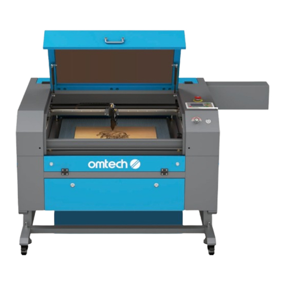
2 Introduction 2.4 Components 2.4.1 Front View... - Page 23 Provides access to the main bay for placing and retrieving materials, as well as fixing the laser path alignment and other Cover maintenance. Power to the laser is automatically cut when the cover is opened. Protects you and others from the laser and its reflection, allowing monitoring of the engraving process.
-
Page 24: Left And Right View
2 Introduction 2.4.2 Left and Right View Left Right Provides access to the second mirror for maintenance and Left Access Door repair. Opens to allow larger pieces of material to be fed through the workbed. Additional care must be taken to avoid seeing or Pass-Through Doors suffering exposure to the laser beam and its reflection, and avoid the heavy material falling down to your feet when taking... -
Page 25: Back View
2.4.3 Back View Top Rear Access Opens to the laser bay, holding the laser tube, its connections, and the Door red dot locator. Produces your engraving laser safely with helium, nitrogen, and CO ₂ gas Laser Tube and water cooled filled inside. Its connection to the laser power supply is extremely high voltage and extremely dangerous. -
Page 26: Laser Path
2 Introduction 2.4.4 Laser Path Mounted on brackets and immobile, it produces the laser. Its connection with Laser Tube the laser power supply is extremely high voltage and extremely dangerous. 1st Mirror Transfers the invisible engraving laser from the tube to the 2nd mirror. 2nd Mirror Moves with the X-axis rail to allow the laser beam to travel along the left Y axis. -
Page 27: Laser Head
2.4.5 Laser Head Moves along the Y axis, with its movement controlled by limit X Axis Rail switches. Transfers the laser from 2nd mirror to the focus lens. Can adjust its 3rd mirror angles. Red Dot Pointer Helps you see the exact position of the invisible engraving laser. With a diameter of 18 mm, directs and focuses the laser beam to its Focus Lens point of contact with the engraving material. -
Page 28: Control Panel
2 Introduction 2.4.6 Control Panel Front Right... - Page 29 Button Description Returns the machine to the saved default parameters. Manually fires the laser. Sets the speed of the current running layer or of the direction keys’ movement. Sets the minimum laser power of the current running layer. Sets the maximum laser power of the current running layer or sets the power of the laser.
-
Page 30: Panel Screen
2 Introduction 2.4.7 Panel Screen... - Page 31 Traces the processed file image during file preview display and Graphic Display Area processing. Displays the file number, speed, and maximum power of the Parameter Display Area current processing file. Displays the coordinate values of the current position of the Coordinate Display Area laser head.
-
Page 32: Electronics Bay
2 Introduction 2.4.8 Electronics Bay Front Right Controls the engraving process, responding to commands Mainboard from your engraving software or the machine's control panel. X-Axis Driver Moves the laser head along the X rail. Y-Axis Driver Moves the X rail along the Y rail. Control Power Supply Powers the machine's control panel. -
Page 33: Laser Power Supply
2.4.9 Laser Power Supply Connects to the laser tube’s anode or positive end, providing high- High-Voltage Wire voltage current to power the laser. Mounting Holes Allows simple installation and removal. Digital Display Provides the real-time current value to the laser tube in milliamps. Laser Indicator Light Illuminates when current is being sent to the laser tube. -
Page 34: Installation
3 Installation Select a location Unpack your engraver 3.1 Selecting a Location 3.2 Unpacking Your Engraver (Page 28) (Page 29) Set up your Set up your exhaust system water cooling system 3.4 Installing the Exhaust System 3.3 Installing the Water Cooling System (Page 35) (Not Included)(Page 30) Connect to your... -
Page 35: Selecting A Location
• Use only the hardware, wiring, and power sources that came with or are compatible with this machine. Installing equipment that your machine is not designed to work with can lead to poor performance, shortened service time, increased maintenance costs, property damage, and personal injury. •... -
Page 36: Unpacking
3 Installation 3.2 Unpacking Your engraver should have arrived in a wooden crate with its accessories (including this manual) packaged in the main bay. You should have placed the crate in a spacious flat area for unpacking, ideally near where you plan to operate the machine permanently. Use at least two people to move and adjust the engraver’s position to help keep it level and avoid any sharp or sudden movement. -
Page 37: Installing The Water Cooling System
7. Inside the main bay, remove the nylon cable ties from the X axis and the honeycomb workbed. You may keep the packaging in case of future return but, if you dispose of it or any accessories, be sure to do so in compliance with applicable waste disposal regulations. 3.3 Installing the Water Cooling System •... - Page 38 3 Installation To connect the water pump to the engraver: Fill a dedicated water tank with distilled water at 15 ℃ –21 ℃ . The tank should always hold at least 2 gallons (7.5 L) of water. If the temperature drops below 0 ℃ , it is recommended to use laser-safe antifreeze. 2.
- Page 39 5. Turn and disconnect the female connector Connector and male connector. Male Connector 6. Connect the female connector to one end of a water hose. Female Connector Water Hose 7. Connect the female connector to the water outlet of water pump. 8.
- Page 40 3 Installation 9. Completely submerge the pump in the water tank. 10. Connect one end of the other white hose to the water outlet at the back of your engraver and secure it with the other hose clamp. 11. Put the other end into the tank in such a way that the returning water flows into the tank without splashing or other problems.
- Page 41 13. Unplug the water pump after confirmation. For an engraver with such high power, it is recommended to use an industrial water chiller for better cooling performance, especially when you are using the machine for a long time. For instructions on installing the water chiller, see the manual of your water cooling system. But keep in mind: •...
-
Page 42: Installing The Exhaust System
3 Installation 3.4 Installing the Exhaust System Wear work gloves to avoid cuts. The provided exhaust pipe extends to a total length of 9.8 ft (3 m). Plan out the route that they will take from your engraver’s fan to a dedicated purifier or—if your engraving fumes and debris will not be hazardous and meet local and national air safety standards—to any window or exterior vent. -
Page 43: Connecting To Power Supply
3.5 Connecting to Power Supply • Fluctuation along the circuit line should be less than 5%. If this is exceeded, the fuse will blow, which is located in the power socket and accessible from the exterior. • Do not connect this device to standard extension cords or power strips. •... -
Page 44: Setting Up Your Control Computer
3 Installation If the outlet is not grounded, use the grounding cable and connect it as follows: a. Fasten the near end of the grounding cable to the ground port at the back of the engraver. b. Connect the far end of the cable to a single metal rod driven at least 8 feet (2.5 m) deep or to two separate metal rods driven at least 4 feet (1.2 m) deep into soil located at least 5 feet (1.5 m) from the machine. -
Page 45: Rdworks V8
A Windows-compatible copy of RDworks V8 is provided on the USB flash drive that came with your engraver. Since Lightburn is also commonly used, this chapter provides instructions to configure these two softwares for the machine. Familiarize yourself with the software’s image design features and laser control settings before using it to operate the laser. - Page 46 3 Installation Click “Test” in the dialogue box that shows up as shown. The connection is successful when the pop- up as shown shows up. Click OK to confirm the connection and close the dialogue box. Click “Exit” to return to the home interface.
-
Page 47: Lightburn
3.6.2 Lightburn Initiate Lightburn on your control computer and connect it to your engraver using the provided USB cable. Click “Device” as shown. Click “Create Manually” in the pop-up that shows up. - Page 48 3 Installation Choose “Ruida” and click “Next”. Choose Serial/USB and then “Next”.
- Page 49 Enter the circled engraver name and X and Y axis length. Click “Next”. SH-G570 Set the origin to “Rear Right” as shown and click “Next”.
- Page 50 Click the device drop list in the lower right corner and choose “SH-G570”. The engraver i s co n n e c t e d w h e n t h e s y s t e m s h ow s “Ready”.
-
Page 51: Initial Testing
3.7 Initial Testing Wear safety glasses during the entire test process! Always make sure the path is clear between the laser and its target. Never allow foreign objects between the laser and the material being engraved. Take care not to leave any part of your body in the laser path when it is in operation. -
Page 52: Cover Shutoff
3 Installation 3.7.2 Cover Shutoff Because of the risk of blindness, burns, and other injuries from direct exposure to the invisible engraving beam, this device shuts off the laser automatically when any one of its protective interlocks is triggered. Always make sure the path is clear between the laser and its target. Never allow foreign objects between the laser and the material being engraved. -
Page 53: Water Shutoff
7. Taking care not to expose yourself to seeing or being hit by any possible reflected laser light, open the cover as little as possible. The laser should pause automatically and an error will be displayed on the control panel. If the laser continues to engrave the design while the cover is raised, the automatic shutoffs are not working and must be repaired before the engraver can be... -
Page 54: Air Assist
3 Installation 3.7.4 Air Assist Because of the danger posed by sparks during engraving and the risk of damage to the laser nozzle and focus lenses from fumes and debris, the pressurized air begins to blow from the laser head when the engraver starts engraving. - Page 55 6. Turn off the engraver and press the Emergency Stop button after the test is done. If any tubing or wiring needs to be adjusted or reconnected, turn off the machine and disconnect it from power before making any such adjustment.
-
Page 56: Operation
4 Operation 4.1 Operation Overview Operate this laser engraver only in accordance with all the instructions provided in this manual. Failure to follow the guidelines detailed here can result in property damage and personal injury. The engraver is operable either through: •... -
Page 57: Pre-Operation Preparation
4.2 Pre-Operation Preparation 4.2.1 Checking Make sure the power supply is ok. 2. Ensure proper ventilation. Make sure that any back-up ventilation systems are in place and running smoothly. NEVER operate the laser if the fan and pipes are not working to purify or remove the fumes produced by the target material. -
Page 58: Powering On
4 Operation 4.2.2 Powering on Turn on the water cooling system. Visually confirm that the water is flowing through the whole system either by opening the top rear door to look at the laser tube itself or by observing that water is entering the machine and returning to the tank through the outlet tube. -
Page 59: Preparing Material
4.2.3 Preparing Material Open the engraver’s cover. 2. Place a sample piece of your material on the workbed. The default location of the laser head’s zero position is at the top left corner of the workbed. This can be changed by moving either your design or the engraver’s origin position using the control panel or your engraving software. -
Page 60: Preparing The Engraving Pattern
4 Operation 4.2.4 Preparing the Engraving Pattern Create the design. You can do this directly in your engraving software or use any other graphics program, saving or converting the file to a format compatible with the engraver. See the full list of acceptable file §... -
Page 61: Engraving
4.3 Engraving • If there is ever an emergency, hit the Emergency Stop button IMMEDIATELY. • DO NOT stare continuously at the active laser even while wearing laser glasses but watch during use for possible issues like sparks and be prepared to quickly extinguish a fire if necessary. - Page 62 4 Operation During repetitive engraving and cutting, • Periodically check your temperature gauge to maintain a water temperature below 100 ℉ (38 ℃ ). If this temperature is reached, stop working and allow your device to cool before further use. •...
-
Page 63: Wrapping-Up
4.4 Wrapping-up Once you have finished engraving, close your software and then turn off your machine in the following order: Close your engraving software, and unplug the USB cable or ethernet cable. 2. Turn the laser key counterclockwise to turn off the laser power. -
Page 64: Rotary Operation (Optional)
4 Operation 4.5 Rotary Operation (Optional) 4.5.1 Installing a Rotary Attachment If the material is too thick, remove the honeycomb bed, aluminum knife bed and the support bar of the blade. 2. Place your rotary axis in an open area. 3. -
Page 65: Instructions For Specific Materials
4.6 Instructions for Specific Materials The following instructions are suggestions to help speed safe work with a range of materials. The user should research the specific safety and engraving requirements of their specific material to avoid the risk of fire, hazardous dust, corrosive and poisonous fumes, and other potential problems. Once the product is known to be safe or appropriate protective equipment has been set up, it can be helpful to engrave a test matrix of small boxes produced at various speed and power settings to discover the ideal settings for your design. -
Page 66: Paper And Cardboard
4 Operation 4.6.5 Paper and Cardboard When engraving various paper products, generally use low to moderate power and fast speed. Test samples from each batch, as only small parameter differences can separate effects that are too light from those that burn through the substrate. As with leather, be especially attentive of the possibility of fire, as well as the dust produced in repetitive applications. -
Page 67: Wood
4.6.10 Wood As with rubber, there is a huge variety of woods and testing your specific material is essential to get the best results. In general, wood with consistent grain and coloring engraves more evenly. Knotted wood produces uneven effects, while resinous wood produces greater edge contrast. Some soft woods like balsa, cork, and pine engrave well (albeit with low contrast) at low or moderate power settings and high speed. -
Page 68: Control Panel Instructions
5 Control Panel Instructions 5.1 Overview You can control your engraver directly from the built-in control panel, through a direct connection with your computer, or over the internet. For details on operating your engraving software, see its separate manual. The built-in control panel can operate the laser manually or engrave designs loaded onto flash drives and external hard drives connected to the USB port on the right side of the cabinet. - Page 69 When running a design from the control console, this will be the main display. The design should appear in the top left corner and its name and the current speed and power settings on the top right. The position of the laser head relative to the workbed appears as the X (horizontal) and Y (vertical) coordinates.
-
Page 70: Setting The Laser Power
5 Control Panel Instructions 5.2 Setting the Laser Power Select Max-Power or Min-Power on the main interface, and the following displays will appear. When is pushed, the green block can move up and down to denote the changing item. Then can be used to change the value. -
Page 71: Function Menu
5.4 Function Menu 5.4.1 Function Interface Press on the main interface to enter the Function interface, as shown below: Push tto select an item, and then push to enter the corresponding submenu. 5.4.2 Adjusting the Z Axis When Z Move is selected, push to control the movement of the Z axis when a motorized workbed (sold separately) is installed. -
Page 72: Resetting The Axes
5 Control Panel Instructions 5.4.4 Resetting the Axes When Axis Reset+ is selected, push and the display will show: Push to select an item. Press start the resetting of the selected axis, and the message “Resetting Is Underway” will show on the screen. -
Page 73: Adjusting The Laser Pulse Mode
5.4.6 Adjusting the Laser Pulse Mode When Laser Set+ is selected, press and the display will show: The operation method is the same as the previous setting. When Continue is selected, press to fire the laser, and release the key to finish firing. - Page 74 5 Control Panel Instructions Details of each item are shown below: Yes or No can be selected. If you select No, the system will use single- origin settings. You can press and set the origin. If you select Multiple Origins Enable Yes, the system will use the multiple-origin settings and on the keyboard becomes invalid.
-
Page 75: Setting Default Parameters
5.4.8 Setting Default Parameters When Set Fact Para is selected, the following interface will be displayed: P u s h a n d t o s e l e c t a password and press to save it. The current parameters of the machine will be stored as its defaults. -
Page 76: Setting The Machine's Ip Address
5 Control Panel Instructions 5.4.11 Setting the Machine’s IP Address When IP Setup+ is selected, press and the display will show: Press to select an item, and push or IP address: to change the parameters. The default address of the engraver is 192.168.1.100. If this is already in use on your local network, use Gatewaya ddress: 192.168.1 for the first three sections and choose... -
Page 77: Setting The Screen Reference
5.4.13 Setting the Screen Reference When Screen Origin is selected, press and the display will show: This interface sets the relative position of the origin. Different origin positions can generate different reflections of the graph over the X/Y axis. The operation method is the same as those described above. -
Page 78: File Management
5 Control Panel Instructions 5.5 File Management 5.5.1 File Interface Select on the main interface, and the following dialogue box will appear: The system will automatically read the memory files. The file name and the work times will be listed and the selected file will be previewed in the upper right corner. -
Page 79: Reading Usb Files
5.5.2 Reading USB Files If Udisk+ is pressed, the display will show: Read Udisk Reads the file list in the inserted USB drive. Copy to Memory Copies the target file to the system. Delete Deletes the selected file from the USB drive. The system supports FAT16 and FAT32 formats, but files can only be identified when placed in the root directory of the flash drive. -
Page 80: Maintenance
6 Maintenance • Adjustment, maintenance, and repair of the electrical components of this machine must be done ONLY by trained and skilled professionals to avoid fires and other malfunctions, including potential radiation exposure from damage to the laser components. Because specialized techniques are required for testing the electrical components of this marking system, it is recommended such testing only be done by the manufacturer, seller, or repair service. -
Page 81: Maintenance Overview
6.1 Maintenance Overview • The use of procedures other than those specified herein may result in hazardous laser radiation exposure. • Before any cleaning or maintenance work, always switch off the device and disconnect it from its power supply. • Always keep the system clean, as flammable debris in the working and exhaust areas constitutes a fire hazard. -
Page 82: Cleaning
6 Maintenance 6.2 Cleaning 6.2.1 Cleaning the Main Bay and Engraver Cleaning Frequency: After each use • Disconnect the engraver from power before cleaning. • Completely wipe dry the surfaces after cleaning. • NEVER allow water to come into contact with the electronic elements. *Depending on what you’ve been engraving, you might need to clean the engraver more or less often. -
Page 83: Cleaning The Water System
6.2.2 Cleaning the Water System NEVER touch or adjust your engraver’s water supply while the pump is still connected to power. Because distilled water can leach chemicals from your tank and/or hoses and spread these possibly corrosive particles to the laser tube, change your water each week regardless of its level or clarity to maximize your laser’s service life. - Page 84 6 Maintenance Detaching the Focus Lens Move the engraving table to a distance of approximately 4 inches (10 cm) under the lens holder. ≈ 4 inches (10cm) 2. Move the laser head into the center of the workbed and put a cloth under the lens holder so that the lens will not be damaged if it accidentally falls from its holder.
- Page 85 4. Remove the laser guide connections by unscrewing the lens holder counterclockwise. Lens Holder 5. Remove the nozzle by rotating it toward you. Nozzle 6. R e m ove t h e l e n s f ro m t h e l e n s h o l d e r b y t u r n i n g t h e l e n s h o l d e r l o c k r i n g counterclockwise with the focus lens repair Focus Lens...
- Page 86 6 Maintenance Cleaning the Focus Lens and Its O-Ring Examine the lens surface, remove coarse dust as well as possible by blowing air onto the lens surface and, if necessary, clean it with the lens cleaning liquid and lens tissue or cloth as below. a.
-
Page 87: Cleaning The Mirrors And Beam Combiner Lens
6.2.4 Cleaning the Mirrors and Beam Combiner Lens The mirrors should be similarly cleaned if there is any debris or haze on their surface. Otherwise, your laser will be less efficient and could have permanent damage on the mirrors. Cleaning Frequency: Once a week, after each use Tools Needed: •... - Page 88 6 Maintenance Mirror Name Mirror Location Cleaning Method In the back left of the 1st Mirror machine beyond the • Avoid press hard enough to grind far end of the Y axis any debris or cause scratching. The end of the laser Beam •...
-
Page 89: Cleaning The Exhaust System
6.2.5 Cleaning the Exhaust System Check and clean the exhaust pipes and fans. The rate of dust accumulation on the exhaust fan and pipe will vary depending on the materials processed and the working environment’s air quality. Cleaning Frequency: Weekly Tools Needed: •... -
Page 90: Water Cooling System
6 Maintenance 6.3 Water Cooling System NEVER touch or adjust your engraver’s water supply while the pump is still connected to power. Always fill the water tank with deionized or distilled water or a custom-purpose laser-safe antifreeze. Using tap water for any purpose but rinsing out cleansers (see §... -
Page 91: Air Assist
6.4 Air Assist Your air assist should arrive preinstalled and correctly wired. Simply check that it is correctly configured and connected every month. If any tubing or wiring needs to be reconnected, shut off all power to the machine (including by pressing the emergency stop) before adjusting anything. Check that its air intake filter is in place, clean, and not obstructed by any nearby objects. -
Page 92: Laser Path Alignment
6 Maintenance 6.5 Laser Path Alignment Having a perfectly aligned laser path is paramount to your engraver’s overall performance. Each of the pro-line series went through a complete beam alignment before shipping. Upon first arrival and about once a week during normal operation, however, it is recommended that the alignment be checked. -
Page 93: Laser Tube Alignment
Place a piece of tape at each stage of the laser path. DO NOT place the tape directly onto the mirror. 2. Turn on the machine. 3. Set the Max. Power (not Min.) parameter to 15% or lower. Any higher percentage will cause the laser to ignite the testing tape instead of marking it. - Page 94 6 Maintenance 4. Press Pulse to manually fire the laser and observe if the laser mark is centered on the tape as below. If so, then the laser tube is aligned with 1st Mirror; if not, continue to step 5. You should be able to see a small mark on the tape.
-
Page 95: 1St Mirror Alignment
6.5.2 1st Mirror Alignment • Wear safety goggles during the entire aligning process. • Avoid attaching the tape directly to any of the mirrors. • Less than 15% of the maximum power (not Min.) should be sufficient to leave a clear mark without setting the testing tape on fire. - Page 96 6 Maintenance 4. Adjust 1st Mirror’s set setscrews accordingly. a. Loosen the nut on the setscrew. b. Slightly turn the setscrew either clockwise or counterclockwise. Setscrew Lower Beam Raise Beam Move Beam Left Lower Beam Right • Each screw adjusts a different position or angle. •...
-
Page 97: 2Nd Mirror Alignment
6.5.3 2nd Mirror Alignment • Wear safety goggles during the entire aligning process. • Avoid attaching the tape directly to the mirror. • Less than 15% of the maximum power (not Min.) should be sufficient to leave a clear mark without setting the testing tape on fire. •... -
Page 98: 3Rd Mirror Alignment
6 Maintenance 6.5.4 3rd mirror Alignment • Wear safety goggles during the entire aligning process. • Avoid attaching the tape directly to the mirror. • Less than 15% of the maximum power (not Min.) should be sufficient to leave a clear mark without setting the testing tape on fire. -
Page 99: Lubrication
6.6 Lubrication 6.6.1 Rail Lubrication Frequency: Every two weeks Tools Needed: • Cotton cloth • White lithium grease Disconnect the engraver from power. 2. Gently move the laser head out of the way. 3. Wipe away all dust and debris along the X and Y axis rails with a dry cotton cloth until they are shiny and clean. -
Page 100: Workbed Elevation Bolts
6 Maintenance 6.6.2 Workbed Elevation Bolts Lubrication Frequency: Every two weeks Tools Needed: • Cotton cloth • White lithium grease KEEP YOUR HAND CLEAR OF THE MOVING WORKBED WHILE APPLYING GREASE. Disconnect the engraver from power. 2. Open the rear access door to access the ball screws. 3. -
Page 101: Parts Replacement
6.7 Parts Replacement • Be sure only to use identical or compatible replacement parts with this engraver. Contact your vendor or our technicians if you have any questions about fitment. Using incompatible components is highly dangerous and waives all the manufacturer’s liability for any damage or injury caused. •... -
Page 102: Troubleshooting
7 Troubleshooting • Adjustment, maintenance, and repair of the electrical components of this cutter must be done ONLY by trained and skilled professionals to avoid fires and other malfunctions, including potential radiation exposure from damage to the laser components. Because specialized techniques are required for testing the electrical components of this marking system, it is recommended such testing only be done by the manufacturer, seller, or repair service. - Page 104 Scan for the latest user manual SH-G570 | 100W | CO Cabinet Laser Engraver User Manual U S B - 5 7 0 1- U 5 R e v. 6 J a n . 2 0 2 5...
Need help?
Do you have a question about the SH-G570 and is the answer not in the manual?
Questions and answers