
Subscribe to Our Youtube Channel
Related Manuals for Omtech K40+


Summary of Contents for Omtech K40+
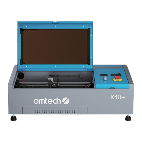
- Page 1 V20241021 K40+ | 40W | CO Desktop Laser Engraver User Manual For Commercial or Industrial Use Only Read Carefully Before Use Keep for Future Reference...
- Page 2 However, constantly running your laser above 70% of its rated power can significantly shorten its service life. Read this manual before use, keep it for future reference, contact OMTech customer service if any point is unclear, and provide it with the machine if it is ever given or sold to another person.
-
Page 3: Help Center
Welcome to the OMTech Community! For helpful hints and instructional videos, visit our Help Center or join our official laser group! If you encounter any issues with your engraver, please feel free to contact us. Our support team will respond ASAP to resolve your concerns. -
Page 4: Table Of Contents
Content 1 Safety Information .................... 1 Disclaimer ..............................1 Symbol Guide ............................. 2 General Safety Instructions ........................3 1.4 Laser Safety Instructions ......................... 4 Electrical Safety Instructions ........................6 1.6 Material Safety Instructions ........................6 Disposal Safety Instructions ........................8 2 Introduction ...................... - Page 5 6 Operation ......................43 6.1 Operation Overview ..........................43 6.2 General Operation ............................. 44 6.2.1 Preparing Your Material ......................44 6.2.2 Focusing Your Laser ........................48 6.2.3 Turning On Your Engraver ......................49 6.2.4 Loading Your Design ........................51 6.2.5 Adjusting the Software’s Parameters ..................
- Page 6 Content 7.3 Water Cooling System ..........................71 7.4 Laser Path Alignment ..........................72 7.4.1 Laser Tube Alignment ......................... 73 7.4.2 1st Mirror Alignment ........................74 7.4.3 2nd Mirror Alignment ........................76 7.4.4 3rd Mirror Alignment ........................78 7.5 Rail Lubrication ............................79 7.6 Parts Replacement ............................
-
Page 8: Safety Information
Read this disclaimer completely and carefully before proceeding with the rest of the manual content. As-Is This OMTech product is sold ‘as is’ and without any express or implied warranties, including but not limited to the implied warranties of merchantability and fitness for a particular purpose. -
Page 9: Symbol Guide
1.2 Symbol Guide The following symbols are used on this machine’s labeling or in this manual: These items present a risk of serious property damage or personal injury. These items address similarly serious concerns about the laser beam. These items address similarly serious concerns about electrical components. These items address similarly serious concerns about fire hazards. -
Page 10: General Safety Instructions
1 Safety Information 1.3 General Safety Instructions • Your engraver should come with instruction labels in the following locations. If any of these labels is missing, illegible, or damaged, it must be replaced. • Use this laser engraving engraver only in accordance with all applicable local and national laws and regulations. -
Page 11: Laser Safety Instructions
• The system must be operated, maintained, and repaired by personnel familiar with the field of use and the dangers of the machine and the material being engraved including its reflectivity, conductivity, potential for creating harmful or combustible fumes, etc. •... - Page 12 1 Safety Information As such, • DO NOT modify or disable this engraver’s provided safety features. Do not modify or disassemble the laser and do not use the laser if it has been modified or disassembled by anyone except trained and skilled professionals. Dangerous radiation exposure and other injury may result from the use of adjusted, modified, or otherwise incompatible equipment.
-
Page 13: Electrical Safety Instructions
1.5 Electrical Safety Instructions • ONLY use this engraver with a compatible and stable power supply with less than 5% fluctuation in its voltage. • DO NOT connect other devices to the same circuit, as the laser system may require its full amperage. - Page 14 1 Safety Information • DO NOT ever under ANY circumstances use this laser engraver if the exhaust system is not working properly. Always ensure that the exhaust fan can remove the dust and gas produced by the engraving process in accordance with all applicable local and national laws and regulations. Immediately stop use if the exhaust fan or vent hose malfunctions.
-
Page 15: Disposal Safety Instructions
This machine CAN NOT be used with the following materials or with any materials that include them: CAN NOT be used • Artificial Leather containing Hexavalent Chromium (Cr [VI]), due to its toxic fumes • Astatine, due to its toxic fumes •... -
Page 16: Introduction
2 Introduction 2.1 General Information This manual is the designated user guide for the installation, setup, safe operation, and maintenance of your laser engraver. It is divided into several chapters covering general information, safety instructions, installation steps, operation and adjustment instructions, maintenance procedures, and contact information. -
Page 17: Specifications
2.3 Specifications Model K40+ Input Power AC 220–240 (V), 50 Hz Power Consumption 350 W Rated Power 40 W Expected Service Life at <40% / 40–70% / >70% Power 2000/1200/600 hr. Laser Wavelength 10640 nm Diameter 1.97 in. 50 mm Laser Tube Length 28.3 in. -
Page 18: Package List
2 Introduction 2.4 Package List... - Page 19 Item Name Qty. Water Pump (With Four Feet and One Connector) Acrylic Focusing Ruler Exhaust Pipe Hose Clamp Power Cord Acrylic Test Plate USB Flash Drive with Engraving Software Included USB Cable Laser Keys Ceramic Testing Resistor with its Separate Manual Double-sided Tape Silicone Sealant Open-end Wrench...
-
Page 20: Components
3 Components 3.1 Front View The cover provides access to the main bay for placing and retrieving materials, as well as fixing the laser path alignment and Cover other maintenance. The power to the laser is automatically cut when the cover is opened. This polycarbonate window protects you and others from the laser and its reflection, allowing monitoring of the engraving process. - Page 21 LED Light Strip The integrated light keeps your workbed easy to see. This gauge monitors the temperature of your laser tube’s cooling water in degrees Celsius ( ± 3 ° C). Do not allow the reading to exceed Temperature Gauge 38 °...
-
Page 22: Rear View
3 Components 3.2 Rear View This door provides access to the laser bay, including the laser tube, Rear Access Door its brackets, its electrical and cooling water connections, and the 1st mirror. This long glass tube is filled with helium, nitrogen, and CO ₂ gas and cooled water to safely produce a powerful laser. - Page 23 This socket connects to your main power supply. Be sure that the Power Socket supply is stable and matches the voltage on the label above the socket. This grounding terminal must be connected to a safe electrical Ground ground if your location does not have a well-grounded 3-prong outlet.
-
Page 24: Laser Path
3 Components 3.3 Laser Path This long glass tube is filled with helium, nitrogen, and CO ₂ gas and cooled water to safely produce a powerful laser. Its connection to the laser power Laser Tube supply is extremely high voltage and extremely dangerous. Although the active laser should be directed into the main bay, its reflections may remain dangerous. -
Page 25: Laser Heads
3.4 Laser Heads This adjustable-angle mirror transfers the laser from the 2nd 3rd Mirror mirror to the focus lens and moves with the laser head to allow the laser beam to travel along the X axis. This knob can be loosened to allow the laser head to move up Manual Focusing Knob or down as needed for manual focus adjustment. -
Page 26: Electronics Bay
3 Components 3.5 Electronics Bay This device provides power for low-voltage components such Low-voltage Power Supply as the mainboard, air pump, and light. This engraver transforms standard electricity into the Laser Power Supply extremely high voltage necessary for the laser tube. These terminal blocks hold your wiring in place for easier part Terminals replacement when needed. -
Page 27: Installation
4 Installation 4.1 Installation Overview A complete working system consists of the laser engraving machine, its integrated air assist and exhaust system, a water tank (not included) with a pump (included), and a USB cable connected to a control computer with the enclosed engraving software. You can also configure additional accessories (such as an industrial water chiller or rotary axis) to suit your needs. -
Page 28: Unpacking
4 Installation • It is highly recommended to have an extra work table nearby to avoid placing objects on or directly adjacent to the engraver, which could become a fire or laser hazard. • Provide 5 feet (1.5 m) of clearance behind the engraver for the fan and 3 feet (1 m) of clearance to the right of the engraver for the electronic bay cooling for maximum efficiency and the left for maintenance. - Page 29 5. Carefully remove any remaining interior packaging and stays—including the strap around the laser head—and set them aside. The laser tube is a highly fragile object and should be handled delicately and as little as possible. 6. Use a hex wrench to unscrew and open the rear cover to check the laser tube for any damage. The laser tube is a highly fragile object and should be handled delicately and as little as possible.
-
Page 30: Installing The Cooling System
4 Installation 4.4 Installing the Cooling System • The provided water pump is essential to your engraver’s performance and longevity. When this laser works without a properly maintained cooling system, its glass tube WILL crack from excess heat. • Always fill the tank with deionized or distilled water or a custom-purpose laser-safe antifreeze. Using tap water will gradually degrade the quality of your engraver and may even cause dangerous mineral buildup within the cooling system. Never use generic antifreeze for the same reason. - Page 31 3. Connect the preinstalled blue Ø12 mm hose on your engraver to the water pump. 4. Completely submerge the pump in the water tank. 5. Place the white Ø12 mm hose into the tank in such a way that the returning water flows into the tank without splashing or other problems.
-
Page 32: Installing The Exhaust System
4 Installation 7. Unplug the water pump after confirmation. As an alternative to manually adjusting the water in your tank, you can also use an industrial water chiller to provide your engraver with temperature-controlled water. We recommend the CW-3000 9L chiller (not included). If using it with this engraver, follow its separate manual and plug it into an outlet on a separate fuse from the engraver itself. -
Page 33: Setting Up The Control System
4.6 Setting Up the Control System Confirm that the labeling beside the power socket at the back of the engraver matches your local power supply and that the power switch is in the O position before setting up the control system. - Page 34 4 Installation 4. Connect the engraver to your computer using the provided USB cable via the USB port. 5. Press the power switch to I. 6. Insert and turn the laser key clockwise.
-
Page 35: Setting Up The Software
You can check for the latest version of LaserGRBL from its official website at lasergrbl.com. For LightBurn and other compatible 3rd party software, contact our customer service, visit the OMTech website, or see our YouTube channel. The next step involves configuring the software. We provide guidance for LaserGRBL and LightBurn exclusively. -
Page 36: Configuring The Lasergrbl
4 Installation 4.7.2 Configuring the LaserGRBL The configurations provided here are only for LaserGRBL users. If you opt to switch from LaserGRBL to Lightburn after installation, reset all personalized settings in LaserGRBL back to their default values, otherwise, interference may occur. To configure the LaserGRBL software: Open the LaserGRBL software on your computer. - Page 37 5. Click Connect to connect to the engraver. The status will change from Disconnected to Idle at the bottom right corner after your engraver has successfully connected. 6. Click Grbl → Grbl Configuration. The Grbl configuration menu should be popped up.
- Page 38 4 Installation 7. In the configuration menu, change Step Direction Invert (Item $3) from 1 to 3 and Homing Direction Invert (Item $23) from 3 to 1. 8. Click Write to save the changes and then click Close to close the menu. 9.
-
Page 39: Configuring The Lightburn
10. Now the software is correctly configured for your engraver. Familiarize yourself with your software’s image design and laser control features before using them to operate the laser. For details on operating the LaserGRBL software, refer to the provided user manual. 4.7.3 Configuring the LightBurn The configurations provided here are only for LightBurn users. - Page 40 4 Installation 2. Click Create Manually. 3. Select GRBL and click Next.
- Page 41 4. Select Serial/USB and click Next. 5. Name the laser and set its X-axis length to 300 mm and its Y-axis length to 200 mm.
- Page 42 4 Installation 6. Choose a corner to use as the machineʼs origin point and click Next. Choosing an origin that differs from the one in y o u r d e s i g n f i l e s c a n result in mirrored output or direct the laser beam outside the intended area,...
-
Page 43: Initial Testing
5 Initial Testing Wear safety glasses during the entire test process! Always make sure the path is clear between the laser and its target. Never allow foreign objects between the laser and the material being engraved. Take care not to leave any part of your body in the laser path when it is in operation. -
Page 44: Emergency Shutoff
5 Initial Testing 5.1 Emergency Shutoff In case of the risk of fire and other hazards during engraving, this engraver includes an easy-to- reach Emergency Stop button. Pressing it down stops the laser tube instantly; turning it clockwise unlocks it. When your engraver arrives, its Emergency Stop button is initially pressed. It must be unlocked before use. -
Page 45: Interlock
5.2 Interlock Because of the risk of blindness, burns, and other injuries from direct exposure to the invisible engraving beam, this device shuts off the laser automatically when any one of its protective interlocks is triggered. Always make sure the path is clear between the laser and its target. Never allow foreign objects between the laser and the material being engraved. -
Page 46: Tray Shutoff
5 Initial Testing 5.2.2 Tray Shutoff After ensuring that the cover shutoff works, you should also test that the tray shutoff activates. Perform the same procedure as before but, instead of opening the cover, open the debris tray. The water protection signal on the display plane should be OFF. The laser should stop completely. -
Page 47: Laser Key Shutoff
5.3 Laser Key Shutoff After ensuring that the interlocks work properly, you should test that the laser key functions correctly. Perform the same procedure as before but, instead of opening the cover or tray, turn and remove the laser key. The laser should stop completely. -
Page 48: Water Shutoff
5 Initial Testing 5.4 Water Shutoff Because of the danger posed by an uncooled laser tube, this engraver also shuts off the laser automatically when its sensors do not detect the correct water flow. You should test that the water shutoff functions correctly. -
Page 49: Air Assist
5.5 Air Assist Because of the danger posed by sparks during engraving and the risk of damage to the laser nozzle and focus lenses from fumes and debris, the pressurized air begins to blow from the laser head when the engraver starts engraving. You should test that the pressurized air blows correctly: Press the power switch to I to turn on the engraver. -
Page 50: Operation
6 Operation Operate this laser engraver only in accordance with all the instructions provided in this manual. Failure to follow these instructions can result in property damage and personal injury. Wear safety glasses during the entire test process! 6.1 Operation Overview This section will address only some of the options and features provided by the operation software. -
Page 51: General Operation
6.2 General Operation 6.2.1 Preparing Your Material Open the cover. 2. Place a sample piece into the main bay following the instructions below. If working with a new material, first check that it can withstand the heat of the laser and will not release harmful fumes when processed. - Page 52 6 Operation Open the tray, remove the honeycomb workbed, and then close the tray. 2. Put the sample piece on the tray. 25 mm–60mm...
- Page 53 Remove the tray and honeycomb workbed. 2. Cover the exposed area of your table with a non-reflective plank, preferably an MDF that fits the space. > 60 mm Warning! Failure to totally cover your table may cause a fire hazard. Using reflective surfaces risks reflecting the laser beam and destroying your engraver.
- Page 54 6 Operation 4. Slide the X-axis rail forward to expose the tray interlock switch. 5. Move the tray interlock switches into a closed position and hold it there by sliding the nearby metal bracket to the right. Tray Interlock Switch Bracket Never leave the switch in this position after completing your work.
-
Page 55: Focusing Your Laser
6.2.2 Focusing Your Laser Move the laser head above the material. 2. Loosen the locking screw on the laser head. 3. Place the focusing ruler between the material and the laser head nozzle. 4. Manually adjust the height of the laser head to make the nozzle touch the top surface of the focusing ruler. -
Page 56: Turning On Your Engraver
6 Operation 6.2.3 Turning On Your Engraver For your safety and that of passersby, this engraver requires two switches to provide power to the laser tube, the front laser key) and the rear power switch. Operators should ALWAYS disable at least one of these switches between uses to prevent unauthorized operation of the machine. - Page 57 4. Turn the Emergency Stop button clockwise to unlock it. Confirm that the air assist and exhaust fan have been activated. 5. Insert and turn the laser key. The display panel should light up. 6. Check the built-in digital display to ensure that the water’s temperature is at an acceptable level. 7.
-
Page 58: Loading Your Design
6 Operation 6.2.4 Loading Your Design Confirm that your control computer has a connection to the engraver via the USB cable. 2. Click File → Open File to import your design into your engraving software. you can create a design using any graphics program, saving or converting the file to a format compatible with the engraver. - Page 59 4. If you have loaded a design to cut, set parameters as follows: • Engraving speed: 600 • Laser Mode: M3-Constant Power • S-MIN: 700 • S-MAX: 700 5. Click Create to save your change. 6. Prepare your designʼs location. a.
-
Page 60: Adjusting The Software's Parameters
6 Operation 6.2.5 Adjusting the Software’s Parameters Customize your design’s contrast and engraving depth by adjusting the speed, power, and other parameters in your engraving software. If you see the power setting in milliamperes on the ammeter, use the following conversion chart to find the appropriate power setting: Power 80%+... - Page 61 Click to outline the projected area for engraving or cutting on your material. The laser traces the boundary, allowing you to ascertain that the laser path is properly aligned with your material setup. 2. Click to start engraving. 3. Watch for possible issues through the view window.
-
Page 62: Shutdown
6 Operation 6.2.7 Shutdown When you have finished your project, close your engraving software. 2. Allow the cooling and ventilation systems to continue to run until the air in the main bay is clear and the tube has safely cooled. 3. -
Page 63: Instructions For Rotary Operation
6.3 Instructions for Rotary Operation 6.3.1 Installing Your Rotary Axis Remove the debris tray and the honeycomb workbed. Set them aside where they will not be damaged or fall over. 2. Gently slide the X-axis rail along the Y axis to the back of the workbed. 3. -
Page 64: Preparing Your Material
6 Operation 5. Place your rotary axis on the non-reflective plank. 6. Open the cover of the control panel. 7. Pull off the Y-axis cable from the board and insert the plug of your rotary axis. 8. If you use LightBurn, enable the rotary axis function in the software following the instructions provided in its separate manual. -
Page 65: Engraving
6.3.7 Engraving § 6.2.6 Engraving on Page 55. If you use LightBurn, adjust the pulse count per rotation parameter when the engraving position in the daily engraving results is not correct. 6.3.8 Shutdown § 6.2.7 Shutdown on Page 57. If you use LightBurn, disable the rotary axis function in the software. 6.3.9 Uninstalling Your Rotary Axis Disconnect the plug of your rotary axis from the board and close the cover of the control panel. -
Page 66: Instructions For Specific Materials
6 Operation 6.4 Instructions for Specific Materials The following instructions are suggestions to help speed safe work with a range of materials. The user should research the specific safety and engraving requirements of their specific material to avoid the risk of fire, hazardous dust, corrosive and poisonous fumes, and other potential problems. Once the product is known to be safe or appropriate protective equipment has been set up, it can be helpful to engrave a test matrix of small boxes produced at various speed and power settings to discover the ideal settings for your design. -
Page 67: Metal
6.4.4 Metal CO ₂ laser engravers should not be used for marking, engraving, or cutting metal. They are best suited for working coatings applied to a metal base, and care must be taken not to attempt work on the underlying metal itself. A variety of coatings specialized for CO ₂ engraving are available, and the user should follow the instructions provided as the parameters vary from product to product and metal to metal. -
Page 68: Stone
6 Operation 6.4.8 Stone When engraving various kinds of stone, generally use moderate power and moderate to fast speed. As with ceramics and glass, be mindful of the dust created (especially for repetitive industrial applications) and take similar measures to ensure the safety of users and others in the work area. 6.4.9 Textiles When engraving textiles like cloth and fleece, generally use low power and fast speed. -
Page 69: Maintenance
7 Maintenance 7.1 Maintenance Schedule The use of procedures other than those specified herein may result in hazardous laser radiation exposure. Before any cleaning or maintenance work, always switch off the engraver and disconnect it from its power supply. Always keep the system clean, as flammable debris in the working and exhaust areas constitutes a fire hazard. -
Page 70: Cleaning
7 Maintenance 7.2 Cleaning ALWAYS allow any fluid used in any cleaning to dry completely before further use of the engraver. 7.2.1 Cleaning the Main Bay and Engraver Check at least once a day whether dust has accumulated in the main engraving bay. If so, it must be removed. - Page 71 • Clean the interior of the main bay thoroughly, removing any debris particles or deposits. P a p e r t owe l s a n d w i n d ow c l e a n e r a r e recommended.
-
Page 72: Cleaning The Focus Lens
7 Maintenance 7.2.2 Cleaning the Focus Lens The lens has a durable coating and won’t be damaged by correct and careful cleaning. You should check the lens and the third mirror daily and clean them if there is any debris or haze on their surfaces. - Page 73 5. Examine the lens’s surface and clean it with a Cotton Swab Laser Optic cotton bud and lens-cleaning fluid as needed until no dust or haze is present. Rolling Roll Across Motion Surface NEVER use the same cleaning tissue twice. Dust accumulated during the first use might scratch the other side of the lens during the second.
-
Page 74: Cleaning The Mirrors
7 Maintenance 7.2.3 Cleaning the Mirrors The mirrors should be similarly cleaned if there is any debris or haze on their surfaces to improve performance and avoid permanent damage. The 1st mirror is located at the back left of the machine beyond the far end of the left Y axis. - Page 75 4. Soak ends of several cotton swabs in denatured or isopropyl alcohol. Saturate swabs with enough solution to be moist, but when pressed against a surface, solution does not squeeze out and drip. 5. With gentle rolling motion, roll swab across surface of lens/mirror to absorb any particulates stuck to surface.
-
Page 76: Cleaning The Exhaust System
7 Maintenance 7.2.4 Cleaning the Exhaust System Check and clean the exhaust system at least once a week. Always cease work and clean your exhaust system if you ever notice the fan making more noise than usual. • Check the internal fan and surrounding ducts for excessive accumulation of dust and debris. For best results, remove the exhaust hose, use a brush, vacuum, or compressed air to remove large accumulations of dust and debris, and use mild cleansers and soft rags or paper towels to fully clean the fan and its blades at least once a month. -
Page 77: Cleaning The Water Cooling System
7.2.5 Cleaning the Water Cooling System NEVER touch or adjust your engraver’s water supply while your engraver is still connected to power. Because distilled water can leach chemicals from your tank and/or hoses and spread these possibly corrosive particles to the laser tube, change your water each week regardless of its level or clarity to maximize your laser’s service life. -
Page 78: Water Cooling System
7 Maintenance 7.3 Water Cooling System NEVER touch or adjust your engraver’s water supply while your engraver is still connected to power. Always fill the water tank with deionized or distilled water or a custom-purpose laser-safe antifreeze. Using tap water for any purpose but rinsing out cleansers (see §... -
Page 79: Laser Path Alignment
7.4 Laser Path Alignment Having a proper beam alignment is important for the overall efficiency of the engraver and the quality of its work. This engraver went through a complete beam alignment before shipping. When the engraver first arrives and about once a week during normal operation, however, it is recommended to confirm that alignment is still at acceptable levels and that the mirrors and focus lens have not shifted due to the movement of the machine. -
Page 80: Laser Tube Alignment
7 Maintenance 7.4.1 Laser Tube Alignment Make sure the laser is well aligned between the laser tube and 1st mirror. Laser Path To test the alignment of the laser tube with the 1st mirror: 1. Cut out a piece of tape and place it on the 1st mirror’s frame. -
Page 81: 1St Mirror Alignment
4. Check the marks on the tap. These marks are OK. These marks require adjustment. The laser mark should be near the center of the hole. If the laser is not centered on the 1st mirror, cut the power to your laser and carefully adjust the laser tube in its brackets. This may require loosening the bolts on its stand. - Page 82 7 Maintenance 2. Once set, place a piece of tape on the 2nd mirror’s frame. DO NOT place the tape directly onto the mirror. § 7.3.1 Laser Tube Alignment 3. Repeat the steps 2–4 from above. 4. If the laser is not centered on the 2nd mirror, you will need to adjust the 1st mirror’s set screws accordingly.
-
Page 83: 2Nd Mirror Alignment
6. Once set, place another piece of tape on the 2nd mirror’s frame. DO NOT place the tape directly onto the mirror. § 7.3.1 Laser Tube Alignment 7. Repeat the steps 2–4 from above. 8. If necessary, adjust the set screws on the 1st mirror. Test again until the beam is well aligned and retighten the nuts on the set screws. - Page 84 7 Maintenance 2. Once set, place a piece of tape on the 3rd mirror’s frame. DO NOT place the tape directly onto the mirror. 3. Repeat the steps and adjustments from § 7.4.2 1st Mirror Alignment above. 4. If necessary, adjust the set screws on the 2nd mirror. Test again until the beam is well aligned and retighten the nuts on the set screws.
-
Page 85: 3Rd Mirror Alignment
7.4.4 3rd Mirror Alignment After ensuring the laser is well aligned between the 2nd and 3rd mirrors, check the alignment between the 3rd mirror and the workbed. Laser Path Unplug the air assist hose from the laser head. 2. Place a piece of tape across the bottom of the laser head and press it onto the nozzle with some force. -
Page 86: Rail Lubrication
7 Maintenance 7.5 Rail Lubrication For best results, clean and lubricate the engraver’s guide rails every two weeks. Turn off the laser engraver. Gently move the laser head out of the way. Wipe away all dust and debris along the X and Y axis rails with a dry cotton cloth until they are shiny and clean. -
Page 87: Parts Replacement
7.6 Parts Replacement ALWAYS completely disconnect the engraver from its power supply before replacing any parts. This engraver should not be modified or disassembled by anyone except trained and skilled professionals, but some consumable parts may require replacement after prolonged use. Be sure only to use identical or compatible replacement parts with this engraver. -
Page 88: Troubleshooting
8 Troubleshooting 8.1 Connection The Engraver Can’t Find Device via USB Issue After powering the device on and connecting it to the computer with a USB cable, the machine’s name can’t be found in the device list. Solution Check and make sure the connection is secure. Check the USB Cable Connection 2. -
Page 89: Hardware
8.2 Hardware 8.2.1 Laser Tube Won’t Light Up Issue The laser tube won’t light up when trying to process after turning on the engraver. Do not touch the laser tube when it is illuminating. Solution As the laser tube ages, more power will be needed for the same Adjust the Laser Power level of laser activation as before. -
Page 90: Engraver Won't Fire Laser
8 Troubleshooting 8.2.2 Engraver Won’t Fire Laser Issue The laser tube lights up as usual, but there is no laser coming out from the laser module. Solution Have a technician check all the mirrors for any missing, misaligned, Check the Installation or incorrect installation or contact our customer service support team for instructions. -
Page 91: Engraver Gets Non-Responsive After Power-On
8.2.3 Engraver Gets Non-Responsive after Power-on Issue After the engraver is powered on by the rear switch and Emergency Stop button, it doesn’t give any response. The ammeter display screen, light panel, water pump, motor, etc. won’t work at all. Solution Check the Power Cable Check if the power cable is properly plugged in on both ends. - Page 92 8 Troubleshooting Scenario 1: If smoke evacuation remains poor If the smoke evacuation is still poor after removing the accessory devices, the issue may be related to the installation of the smoke exhaust fan. Check the smoke exhaust Ensure that the smoke exhaust pipe is not pressed or bent, pipe hindering proper smoke evacuation.
-
Page 93: Not Cutting Through The Material
8.3.2 Not Cutting Through the Material Issue The engraver won’t fully and effectively cut through the material as expected. Solution For the materials suggested in this manual, you can choose the recommended parameter values for cutting. Check the Processing Parameters For those not suggested, you can get the ideal parameter values after several tests. -
Page 94: Poor Engraving Results
8 Troubleshooting 8.3.3 Poor Engraving Results Issue When this issue occurs, you may find the engraving performance is not as expected: the pattern appears blurry, and the engraving outcome is excessively darkening or too shallow to be identified. Solution For materials suggested in this manual, you can choose the recommended parameter values for cutting. -
Page 95: Engraving Image Shifts During Processing
8.3.4 Engraving Image Shifts during Processing Issue The engraved image is deviated or won’t close up because of the losing steps in processing. Solution If the processing speed is too fast, it may cause step loss. Lower the Speed of the Engraving Process Please try again by lowering the speed. - Page 98 Scan for the latest user manual K40+ | 40W | CO Desktop Laser Engraver User Manual U S B - 0 3 0 2 - X 3 R e v. 2 1 O c t . 2 0 2 4...
Need help?
Do you have a question about the K40+ and is the answer not in the manual?
Questions and answers