
Subscribe to Our Youtube Channel
Related Manuals for Omtech PRO 3655


Summary of Contents for Omtech PRO 3655
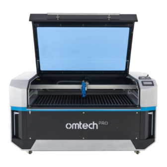
- Page 1 V20240531 PRO 3655 Cabinet Laser Engraver User Manual Read Carefully Before Use Keep for Future Reference...
- Page 3 .pdf copy of the latest version of this manual, use the appropriate app on your smartphone or other engraver to scan the QR code to the right. Come join the omtech community at our official laser group on Facebook or visit the company forums at omtechlaser.com. Check our YouTube channel for helpful hints and instructional videos.
-
Page 4: Table Of Contents
Content 1. Safety Information ..................1 Disclaimer ............................... 1 Designated Use ............................. 1 Symbol Guide ............................2 1.4 General Safety Instructions ........................ 3 Laser Safety Instructions ........................4 1.6 Electrical Safety Instructions ......................5 Material Safety Instructions ....................... 7 2. Introduction ....................9 General Information .......................... - Page 5 4.4 Water Shutoff ............................57 4.5 Air Assist Shutoff ..........................57 4.6 Laser Path Calibration ......................... 58 4.7 Security ..............................58 5. Typical Operation Sequence ..............59 Operation Overview ..........................59 5.2 Pre-Operation Preparation ......................... 60 5.2.1 Checking ............................ 60 5.2.2 Powering On ..........................
- Page 6 Content 6.6.4 IO Diagnosis ..........................90 6.6.5 Frame Cutting .......................... 91 6.6.6 Setting Laser Head Return ....................91 6.6.7 System Reset ........................... 92 6.7 Menu Submenu ............................. 93 6.7.1 SysCfg ............................93 6.7.2 Language Settings ........................99 6.7.3 User Parameters ........................99 7.
-
Page 8: Safety Information
1. Safety Information 1.1 Disclaimer This manual is the designated user guide for the installation, setup, safe operation, and maintenance of your cabinet laser engraver. ALL personnel involved in the installation, setup, operation, maintenance, and repair of this machine should read and understand this manual, particularly its safety instructions. Some components are extremely high voltage and/or produce powerful laser radiation. -
Page 9: Symbol Guide
1.3 Symbol Guide The following symbols are used on this machine’s labeling or in this manual: These items present a risk of serious property damage or personal injury. These items address similarly serious concerns about the laser beam. These items address similarly serious concerns about electrical components. These items address similarly serious concerns about fire hazards. -
Page 10: General Safety Instructions
1. Safety Information 1.4 General Safety Instructions • Your device should come with instruction labels in the following locations: If any of these labels is missing, illegible, or becomes damaged, it must be replaced. • Use this laser engraving device only in accordance with all applicable local and national laws and regulations. -
Page 11: Laser Safety Instructions
• Any untrained personnel who might be near the device while it is in operation MUST be informed that it is dangerous and fully instructed on how to avoid injury during its use. • ALWAYS keep a fire extinguisher or other flame-retardant system nearby in case of accidents. Ensure that the local fire department’s phone number is clearly displayed nearby. -
Page 12: Electrical Safety Instructions
1. Safety Information • DO NOT ever under ANY circumstances use this laser engraver if the water cooling system is not working properly. Always activate the water cooling system and visually confirm that water is flowing through the entire system before turning on the laser tube. Immediately stop use if the water cooling system malfunctions. - Page 13 • DO NOT drain or fill the integrated water tank while it is connected to its power supply. Disconnect the chiller and the laser from power before adjusting the cooling liquid level. Do not allow any electronic component to become wet and, if any accidentally does become wet, leave the entire system disconnected from power until all components are fully dry.
-
Page 14: Material Safety Instructions
1. Safety Information 1.7 Material Safety Instructions • Users of this laser engraving machine are responsible for confirming that materials to be processed can withstand the heat of the laser and will not produce any emissions or byproducts either harmful to people nearby or in violation of local or national laws or regulations. In particular, do not use this device to process polyvinyl chloride (PVC), Teflon, or other halogen containing materials under any circumstances. - Page 15 This machine CANNOT be used with the following materials or with any materials that include them due to the toxic fumes they will release when being engraved: • Artificial Leather containing Hexavalent Chromium (Cr [VI]) • Astatine • Beryllium Oxide •...
-
Page 16: Introduction
2. Introduction 2.1 General Information Your laser engraver works by emitting a powerful laser beam from a glass tube filled with excited carbon dioxide ( CO₂ ), catalyzing nitrogen (N ₂ ), and insulating helium (He), reflecting that beam off three mirrors and through a focus lens, and using this focused light to cut and etch designs into certain substrates. - Page 17 Non-Metal Non-Metal Engraving Cutting The water-cooling system or its equivalent must be used with this engraver to dissipate the heat produced by the laser tube. Similarly, an exhaust system—typically either an external vent or a dedicated air purifier—must be used with the provided fan to remove the dust and gases produced by the engraving process.
-
Page 18: Technical Specifications
2. Introduction 2.2 Technical Specifications Model PRO 3655 Diameter 3.15 in. 80 mm Laser Tube Length 57.1 in. 1450 mm Max. Input Power (Laser and Motors) 1300 W Rated Power 130 W 150 W Wavelength 10640 nm Diameter 0.79 in. - Page 19 Max. Engraving Depth 0.04 in. 1 mm Min. Engraving Depth 0.0004 in. 0.01 mm Min. Letter Size 0.04×0.04 in. 1×1 mm Positioning Accuracy ± 0.0008 in. ± 0.02 mm Number Aluminum Bed Blades Load Capacity (ea.) 8.4 oz. 240 g Honeycomb Bed Dimensions 41.3×25.5 in.
-
Page 20: Components
2. Introduction 2.3 Components 2.3.1 Package List Items Qty. Items Qty. Toolkit Ethernet Cable External Fan (with power cord) USB Flash Drive (preloaded with RDWorks V8) Exhaust Pipes Limit Switch Hose Clamps (150 mm) Laser Glasses (OD5+) Hex Wrench Set Power Cords (15 A) Flathead Screwdriver Focal Lens Tools... - Page 21 Use this to raise and lower the cover. The laser is automatically disabled Handle when the cover is opened. The cover provides access to the main bay for placing and retrieving Cover materials, as well as fixing the laser path alignment and other maintenance.
- Page 22 2. Introduction Left Side Right Side...
- Page 23 This door provides access to the left Y-axis rail, its motor, and the 2nd mirror. For all of the engraver’s access doors, unlock, open, and rotate Top Left Access Door the handles found on each end together. When the latches are freed, carefully support the door as it opens to avoid damage.
- Page 24 2. Introduction Rear This door provides access to the laser bay, including the Rear Access Door laser tube, its brackets, its electrical and cooling water connections, and the 1st mirror. During use, the gas mixture inside this long glass tube produces a powerful laser.
- Page 25 Air Intake Main Power This port powers the engraver itself. Chiller Power This port powers the integrated chiller. These are the main power switches for the engraver and the Circuit Breakers chiller. They should be flipped off between sessions, as well as during any repair or maintenance.
-
Page 26: Laser Path
2. Introduction 2.3.3 Laser Path The glass tube that produces the laser is mounted on Laser Tube brackets and is immobile. Its connection with the laser power supply is extremely high voltage and extremely dangerous. This adjustable-angle mirror is fixed in place to transfer the 1st Mirror invisible engraving laser from the tube to the 2nd mirror. -
Page 27: Laser Head
2.3.4 Laser Head This adjustable-angle mirror transfers the laser from the 2nd 3rd Mirror mirror to the focus lens. This rail moves along the Y axis, with its range controlled by X-Axis Rail limit switches. This 20 mm lens directs and focuses the laser beam to its Focus Lens point of contact with your material. -
Page 28: Control Panel
2. Introduction 2.3.5 Control Panel Right Front This lock turns the laser power supply on and off, helping Laser Key ensure that only approved operators can use your engraver. This digital display shows the current being provided to the laser tube in mA. The knob to its right is its master power Ammeter control. -
Page 29: Water Chiller
2.5 Water Chiller Left Back Use this port once it is time to refill the tank with deionized or distilled Fill Port water, or laser-safe antifreeze. Your water-cooling system should always be on during the use of the Power Switch laser but should be switched off during draining, refilling, cleaning, repair, and other maintenance. -
Page 30: Electronics Bay
2. Introduction 2.6 Electronics Bay Right Front This circuit board controls the engraving process, responding to Mainboard commands from your engraving software or the machine’s control panel. Z-Axis Driver This device controls the motor that raises and lowers the workbed. Rotary-Axis Driver This device directs attached and enabled rotary devices. - Page 31 Right Front Laser Signal Indicator This light shows when current is being sent to the laser tube. This terminal block holds the power supply’s connection to the Main Power Terminal engraver’s grounding (FG) and to the main power supply (AC). This button is used to attempt to test fire the laser when troubleshooting problems.
-
Page 32: Touchscreen
2. Introduction 2.7 Touchscreen System time System State Area Display Areas Definitions&Functions Graphic Display Shows the currently loaded image and, during work, the position of the Area laser head. File Shows the name of the file being processed. Shows the batch count and the total count (the current Count batch count for work with the currently loaded file;... - Page 33 Display Areas Definitions&Functions Frame Traces the outline of the current design for sizing. Focus Enables the laser head to automatically focus. Function Area Start Starts the current task. Stop Stops the current task. When the strip of the display that shows the time is tapped, the control Keyboard Lock panel will be locked, with the panel displaying on the right corner of...
-
Page 34: Installation
3. Installation 3.1 Installation Overview A complete working system consists of the following parts: • A laser engraving cabinet The cabinet can use designs provided by the enclosed engraving software by direct or internet connection with your computer; it can also engrave designs loaded directly from a flash drive. •... - Page 35 • Provide 5 feet (1.5 m) of clearance behind the engraver for the chiller’s fans and 3 feet (1 m) of clearance to the right of the engraver for the electronic bay’s fans for maximum efficiency. 5 feet (1.5 m) 3 feet 3 feet (1 m)
-
Page 36: Unpacking Your Engraver
When your new engraver is delivered, the chiller is not filled with fresh laser-safe omtech antifreeze for safety during shipping. Users must fill the chiller with laser- safe antifreeze before operation. Any leak during or after unpacking should be carefully cleaned to avoid direct contact or inhalation of the fumes. -
Page 37: Electrical Grounding
5. Open the rear access door to carefully check the laser bay and bottom left access door for any leakage. Once all tubes are checked, fill the chiller tank to a level near the top of the green NORMAL range on the gauge with more laser-safe antifreeze or pure distilled water. 6. -
Page 38: Water Cooling Installation
NEVER adjust the water level within the chiller while it and the laser are connected to power. Fill the Water Chiller Your chiller arrived with no distilled water or omtech laser-safe antifreeze. You should fill the water chiller before operation (See § Refilling on Page 117). - Page 39 3. Wait for a couple of minutes and check the cooling liquid level in the chiller. If it is below NORMAL, to fill the tank again: a. Open the rear access door to carefully check the laser bay and bottom left access door for any leakage.
- Page 40 3. Installation ⯆ 4. During its first use, press to speed the activation of the compressor. 5. Once the chiller is fully operational, its cooling liquid should begin to run through your machine and back into your tank. Pay attention to the following: •...
-
Page 41: Exhaust System
3.6 Exhaust System Installation The exhaust system is used to remove fumes and dust produced during engraving to keep your workspace clean and safe. The fan can be plugged into the outlet on the back of the engraver if the water chiller use a dedicated line or if you have prepared a robust circuit able to handle the full load of the entire machine. - Page 42 3. Installation To install the external fan: A t t a c h o n e o f t h e p rov i d e d Ø 1 5 0 m m exhaust hoses directly onto the exhaust vent on the rear of the engraver, fastening it into place with one of the hose clamps.
-
Page 43: Air Assist
3.7 Air Assist System Installation The air assist system for normal non-metal cutting and engraving should arrive preinstalled and correctly wired. Simply check that it is correctly configured and connected as shown. If any tubing or wiring needs to be reconnected, shut off all power to the machine (including by pressing the emergency stop) before adjusting Left... -
Page 44: Control Computer
3. Installation 3.8 Control Computer See the software manual for details on the requirements for the control computer. The control computer can be connected directly using the provided USB cable or through Wi-Fi. If the control computer is directly connected to the engraver, it should not be placed more than 15 feet (4.5 m) away to avoid possible interference to the signal on its line. -
Page 45: Rdworks V8 Reverse Compensation
3.8.1 RDWorks V8 Reverse Compensation Insert the provided USB flash drive into a port on your control laptop. Find the file as shown. RDWorksV8Setup8.01.57. Click open the file and click “Install”. Choose a file route that you deem suitable. When the installation is finished, click to run the program. - Page 46 3. Installation Choose “Scanning (Reverse compensation)” under the directory of the provided flash drive. Click “Optimize” again to ensure that the Engraver Reverse Offset has been imported as shown. Tick the box before “Scanning (Reverse compensation)”...
-
Page 47: Lightburn Scanning Offset
3.8.2 Lightburn Scanning Offset Click open your Lightburn, then “Edit”, and then “Device Settings”. Click “Import” in the pop-up that shows up. Find and choose the “Scanning Offset Adjust” in the provided flash drive. -
Page 48: Connection Through The Usb Cable
3. Installation Enable the scanning offset adjustment by clicking green the toggle switch as shown. 3.8.3 Connection Through the USB Cable RDWorks V8 I n i t i a t e R D Wo r k s V 8 o n y o u r c o n t r o l computer and connect it to the engraver using the provided USB cable. - Page 49 Click to tick the box as shown. Click “Modify”. Click “Test” in the dialogue box that shows up as shown. The connection is successful when the pop- up as shown shows up.
- Page 50 3. Installation Click OK to confirm the connection and close the dialogue box. Click “Exit” to return to the home interface. Lightburn Initiate Lightburn on your control computer and connect it to your engraver using the provided USB cable. Click “Device” as shown.
- Page 51 Click “Create Manually” in the pop-up that shows up. Choose “Ruida” and click “Next”.
- Page 52 3. Installation Choose Serial/USB and then “Next”. Enter the circled engraver name and X and Y axis length. Click “Next”. PRO 3655 1400...
- Page 53 Set the origin to “Rear Right” as shown and click “Next”. Confirm your configuration and click “Finish” to close the pop-up. PRO 3655 1400mm x 900mm...
-
Page 54: Connection Through Wi-Fi
3. Installation Click the device drop list in the lower right corner and choose “PRO 3655”. The engraver is connected when the system shows “Ready”. PRO 3655 3.8.4 Connection Through Wi-Fi RDWorks V8 Enable Wi-Fi on your computer. Search or 3655 select network “OMTECH PRO 3655”. - Page 55 Click to tick the box before “Device”, being sure the IP address is as shown. Click “Modify”. Set the IP address to “192.168.1.20” in the pop- up that shows up. Click “Test”.
- Page 56 Click “Exit” to return to the home interface. Lightburn Enable Wi-Fi on your computer. Search or 3655 select network “OMTECH PRO 3655”. Enter the passcode (123456abc) to connect your control computer to the laser engraver. Initiate Lightburn and click “Device: in the...
- Page 57 Click “Create Manually” in the dialogue box as shown. Choose “Ruida” from the list and click “Next”.
- Page 58 3. Installation Choose Ethernet/UDP and click “Next’ in the pop-up as shown. Enter “192.168.1.20” in the dialogue box as shown. Click “Next”.
- Page 59 Enter the engraver name, X axis length, and Y axis length as shown. Click “Next”. PRO 3655 1400 Set the engraver origin to “Rear Right” and click “Next”.
- Page 60 PRO 3655 1400mm x 900mm Click the device drop list in the lower right corner and choose “PRO 3655”. The engraver is connected when the system shows “Ready”. DO NOT connect your computer to the engraver with a network cable. The...
-
Page 61: Main Power Connection
3.9 Main Power Connections Under NO circumstances should you switch on the engravers if the voltages do not correspond or if your circuits will be unable to handle the necessary load. Fluctuation along the lines should be less than 5%. If it is exceeded the engravers’ own fuses will blow to protect its internal electronics. -
Page 62: Initial Testing
4. Initial Testing 4.1 Emergency Shutoff Because of the risk of fire and other hazards during engraving, this engraver includes a large and easy-to-reach emergency stop (E-Stop) button near the control panel. Press it down to stop the laser tube instantly. Right Emergency Stop Front... -
Page 63: Emergency Switch
Tap Z+, Z–, X+, X–, Y+, and Y– so that that the laser head is about 1 or 2 inches above the laserable scrap. 9. Hold and the laser head should start firing laser beam continuously. Hit the emergency stop and observe whether the laser stops instantly. If the laser continues to fire, the laser key is not working and must be replaced before the engraver can be used. -
Page 64: Water Shutoff
4. Initial Testing 4.4 Water Shutoff Because of the danger posed by an uncooled laser tube, this engraver also shuts off the laser automatically when the water cooling system malfunctions. After ensuring that the emergency stop button and cover protection both work, test that the water shutoff works properly before conducting any other work on your machine. -
Page 65: Laser Path Calibration
Attempt to fire the laser again. If the laser fires, the automatic shutoff is not working and must be repaired before the engraver can be used. Turn off the machine and contact customer service. If the laser does not fire, the automatic shutoff is working fine; simply release the hose to restore access to the air intake and continue setting up your engraver. -
Page 66: Typical Operation Sequence
5. Typical Operation Sequence 5.1 Operation Overview Operate this laser engraver only in accordance with all the instructions provided in this manual. Failure to follow the guidelines detailed here can result in property damage and personal injury. The engraver is operable either through: •... -
Page 67: Pre-Operation Preparation
5.2 Pre-Engraving Preparation 5.2.1 Checking Make sure the power supply is ok. 2. Check and fill the water chiller. a. Inspect the water chiller’s gauge to ensure that your cooling liquid is completely clear and in the upper half of the green “NORMAL”... - Page 68 5. Typical Operation Sequence 6. Adjust the workbed if necessary. Honeycomb Bed For lightweight materials requiring close support: wood, fabric, leather, thin veneers Aluminum Knife Bed For heavy or rigid materials that are self-supporting and might damage the honeycomb bed and heat-sensitive materials (for example, acrylic, plastic) needing high airflow to avoid surface damage Steel Saw Blade Bed...
-
Page 69: Powering On
5.2.2 Powering on Flip both circuit breaker switches to the ON position. 2. Turn on the water chiller by pressing POWER switch to — position. For detailed information about water chiller temperature setting, see § 7.2 Water Chiller Adjustment (Page 106). §... - Page 70 5. Typical Operation Sequence 5. Use the key to activate the laser lock. 6. Turn the ammeter knob clockwise to its maximum setting. 7. Flip the light switch below the Ethernet port to — position for best view results. 8. Wait until the engraver is in the standby mode and ready to use.
-
Page 71: Preparing The Material
5.2.3 Preparing Material 1. Open the engraver’s cover. 2. Place a sample piece of your material on the workbed. The default location of the laser head’s zero position is at the top right corner of the workbed. This can be changed by moving either your design or the engraver’s origin position using the control panel or your engraving software. -
Page 72: Preparing The Engrave Pattern
5. Typical Operation Sequence 5.2.4 Preparing the Engraving Pattern Step 1. Create the design. Create the design that you’d like to engrave or cut. (See § 5.5 for engraving spherical or cylindrical objects.) You can do this directly in your engraving software or use any other graphics program to create the image and set its engraving parameters. - Page 73 Tap the parameter box to show the numeric keyboard as shown. Set the value to that you desire. Tap OK to confirm the modification and exit the current menu or tap ESC to cancel the modification and exit the current menu. The exact speed value deepends on the material, its thickness, among §...
- Page 74 5. Typical Operation Sequence Power Levels • All powers are displayed as percentages (%) of the engraver’s rated power. Running your laser above 70% risks shortening your laser’s service life. If you find power settings of 70% or lower do not produce the results that you need, for most materials it is better if you first attempt to increase the amount of energy per unit area by slowing the laser or running more loops before further increasing the power setting itself.
- Page 75 Step 3. Place a sample piece of your material on the workbed. • The standard location is in the top right corner of the workbed. This can be changed by moving either your design or the engraver’s origin position using the control panel or your engraving software.
-
Page 76: Autofocusing
5. Typical Operation Sequence 5.2.5 Autofocusing Tap the focus icon and the laser head should start move toward the simple material, stopping when the correct focal height has been reached. • It is recommended that you start each session by pressing . -
Page 77: Engraving Proper
5.3 Engraving Proper Step 1. to engrave your design. Step 2. on the control panel to completely stop work, return to the beginning of the design, and reset the laser head back to its origin Step 3. Open the cover and check that the engaved pattern is desired. If not, adjust the §... - Page 78 5. Typical Operation Sequence Step 2. Once you have finished engraving, close your software and then turn off your machine in the following order: Turn and remove your laser key. Turn the ammeter down. Press the emergency stop. Allow time for the ventilation and cooling systems to continue running, cooling the laser and removing any remaining fumes or dust.
-
Page 79: Rotary Operation
5.5.1 Installing a Rotaty Attachment Cut the power to the engraver before installing the attachment. PRO 3655 does not come with a rotary attachment but is compatible with standard four-pin models. Remove the steel saw bed or the aluminum knife bed and the support bar of the blade. -
Page 80: Engraving Procedures With A Rotary Attachment
5. Typical Operation Sequence 5.5.2 Engraving Procedures with a Rotary Attachment In typical workflows, designs are created by using graphic files on a control computer, then transferred to the engraver for execution. Here are the main operation steps: Start Check and power on Prepare your material Prepare your design file and set parameters... -
Page 81: Engraving Procedures Proper
5.5.3 Engraving Procedures Proper Step 1. Prepare your engrave material per § 5.2 Pre-Operation Preparation. Step 2. Tap “Manual” in the main menu, and the following menu pops up. Step 3. Insert the provided focal height ruler b e t we e n t h e l a s e r h e a d a n d t h e obeject to te engraved. -
Page 82: Instructions For Specific Materials
5. Typical Operation Sequence 5.6 Instructions for Specific Materials The following instructions are suggestions to help speed safe work with a range of materials. The user should research the specific safety and engraving requirements of their specific material to avoid the risk of fire, hazardous dust, corrosive and poisonous fumes, and other potential problems. Once the product is known to be safe or appropriate protective equipment has been set up, it can be helpful to engrave a test matrix of small boxes produced at various speed and power settings to discover the ideal settings for your design. -
Page 83: Leather
Leather When engraving leather products, generally use low to moderate power at high speed. Be especially attentive to the possibility of fire, as well as the dust produced in repetitive applications. Thickness Despcrition 1/16 in. 1/8 in. 1/4 in. 1/2 in. Power (%) 130 W Speed (mm/s) -
Page 84: Plastics
5. Typical Operation Sequence Plastics Plastics for engraving are available in many different colors and thicknesses and with many different coatings and surfaces. The majority of available plastics can be well engraved and cut with the laser. Plastics with a microporous surface seem to give the best result, because less surface material needs to be removed. -
Page 85: Textiles
Textiles When engraving textiles like cloth and fleece, generally use low power and fast speed. As with leather, be especially attentive to the possibility of fire and dust. Wood As with rubber, there is a huge variety of woods and testing your specific material is essential to get the best results. -
Page 86: Touch Screen Operations
6. Touch Screen Operations 6.1 Overview Operate this laser engraver only in accordance with all the instructions provided in this manual. Failure to follow the guidelines detailed here can result in property damage and personal injury. Right Front Left Back There are also small adjustable digital displays for the air assist system located behind the bottom left access door and for the laser power supply located behind the bottom right access door, but these should never be adjusted or need... - Page 87 All the settings and parameters on the touchpad can be accessed and changed through tapping. For settings that pop out, their alterations and confirmations are done through tapping Enable or Disable. Tap OK to save the change. For parameters with numeric values, Tap the value to enter the value, and a numeric keyboard shows up as shown: Enter the value needed and tap OK to save...
-
Page 88: File Management
6. Touch Screen Operations 6.2 File Management System Memory Files In the main menu, tap File, and the following menu pops up. Files are listed in the left column and a preview of a selected file is shown in the graphic display area. - Page 89 USB Files • The system is compatible with FAT32 and FAT16 USB file formats. For best results, however, store your files under the root directory of the USB flash drive so that the system can recognize them quicker and easier. •...
-
Page 90: Setting Speed Levels
6. Touch Screen Operations 6.3 Setting Speed Levels Tap Speed in Parameter Display Area from the home menu, and the following menu shows up. • When the system is idle, the speed parameters controls the manual high speed and manual low speed. That is, the speed range that the laser head can be manually moved to reach, which is convenient for debugging and calibrating. -
Page 91: Setting Power Levels
6.4 Setting Power Levels • All powers are displayed as percentages (%) of the engraver’s rated power. Running your laser above 70% risks shortening your laser’s service life. • If you find power settings of 70% or lower do not produce the results that you need, for most materials it is better if you first attempt to increase the amount of energy per unit area by slowing the laser or running more loops before further increasing the power setting itself. -
Page 92: Setting File Parameters
6. Touch Screen Operations 6.5 Setting File Parameters When in the main menu, tap the filename of the file to be processed on the left upper corner, and the menu as shown pops up. Submenus Functions Encompasses the speed and power, which can be customized for each layer of the file under this filename to your needs. - Page 93 Icons Functions Repeat times Sets how many times the process will be repeated. Repeat delay Sets the interval between two repeated processing. Once the repeat times and delay has been set and saved, the change will apply to all the files that are currently on the system’s worklist unless it suffers a power breakout or being turned off.
- Page 94 6. Touch Screen Operations Icons Functions Sets how many continuous times the system feeds the laserable workpiece Feeed Time during one engraving task. Feed Length Controls the length of the workpiece that is conveyed onto the workbed. Feed Delay Sets the interval between two consecutive workpiece feed. Submenus Functions Encompasses all the array information of the file under the filename that you...
- Page 95 Listed on the left are all the array names for this file. Use the up and down button to scroll through all the array names if there are many of them. After being tapped, the information of the selected array is displayed as shown Icons Functions direction*...
-
Page 96: Setting Axes' Movement
6. Touch Screen Operations 6.6 Setting Axes’ Movement Tap Manual in the main menu, and the following menu pops up. This menu is mainly for manual debugging, including axes (X, Y, Z, & U) motion, manual laser firing, positioning, IO diagnosis, frame cutting, return and system reset, and aligning the laser path. To exit this menu, tap Auto in this menu. -
Page 97: Manual Laser Firing
Continuous Movement To check that the laser head and the workbed can move continuously under manual mode: Tap Manual mode and select the other option than step. 2. Tap to use a set slow or fast speed. When S is in blue, the selected axis travels at a slow speed. -
Page 98: Frame Cutting
6. Touch Screen Operations 6.6.5 Frame Cutting Tap CutF, and the menu as shown pops up. To cut a frame at a set distance from the outer circumference of the design file: Tap the box after Frame mode and choose Frame Laser On. -
Page 99: System Reset
Under XY return to, there are four options for the laser head’s return: ABS position, Not return, Origin pos, and Docking point. Icons Functions Sets the laser head to return ABS postion t o t h e m e c h a n i c a l o r i g i n along the X and Y axis. -
Page 100: Menu Submenu
6. Touch Screen Operations 6.7 Menu Submenu Tap Menu in the main menu, and the menu submenu shows up as shown. This menu includes SysCfg, Lang, User, Vendor, and Main. 6.7.1 SysCfg Ethernet Tapping Ethernet accesses the IP setting. Tap to change the value and tap OK to save your change. Sysinfo Tapping SysInfo accesses the system information menu, where the product activation and time zone can be set. - Page 101 Product Activation T a p M e n u > S y s C f g > S y s i n f o > P r o d u c t Authorization, and the pop-up as shown shows up. 2.
- Page 102 6. Touch Screen Operations Setting Multi-Origins Tap Origin from the SysCfg menu, and the menu as shown shows up. To enable this menu, tap the box after Multi-origins enable and set the option to Enable. With Disable selected, the system has a single default origin that the laser head returns to. There are four customizable Origins.
- Page 103 Manually Seting an Origin Tap to choose an origin, Origin 1 as is in the case demonstrated below. 2. Tap . And the menu as shown shows up. 3. Use the keys (Z+, Z–) and the arrows to move the laser head to a desired position in relation to the workbed.
- Page 104 6. Touch Screen Operations Backing up Factory Parameters Tap Back Up, and the menu as shown shows 2. Tap “Confirm to backup parameters” to back up the current set parameter values. 3. Enter your passcode in the pop up that shows up.
- Page 105 Restore Factory Parameters Tap “Restore”, and the menu as shown shows up. To restore factory parameter values: Tap “Confirm to restore default parameters to controller!” 2. Put in your passcode. 3. Tap OK. Setting the Screen Orientation Tap Display, and the menu as shown shows 2.
-
Page 106: Language Settings
6. Touch Screen Operations 6.7.2 Language Settings Tap Menu>Lang, and the menu as shown shows up. 2. Tap to select a language that you desire to use. The change will take effect immediately after a language is selected, and the system returns to the main menu automatically. - Page 107 Reset Submenu Parameters Options Functions/Meanings Origin pos Sets the laser head to return to the default origin. ABS position Sets the laser head to return to the mechanical origin. Reset to Docking Point Sets the laser head to return to the preset origin(s). Not return Keeps the laser where it is.
- Page 108 6. Touch Screen Operations Parameters Options Functions/Meanings XY Reset speed (mm/s) Numerical Sets the laser head’s return speed along the X and Y axes. Z Reset speed (mm/s) Numerical Sets the laser head to its Z origin upon powering up. U Reset speed (mm/s) Numerical Disabled...
- Page 109 Focus Submenu Parameters Options Functions/Meanings Enables or disables the auto-focusing of the laser Auto focus Enable/Disable head. Focus sensor Z limit Selects the focus sensor. Focus length(mm) Numerical Sets the focal length. Material thickness (mm) Numerical Sets the material thickness. Focus speed (mm/s) Numerical Sets the focusing speed of the laser head.
- Page 110 6. Touch Screen Operations Engrave Submenu Parameters Options Functions/Meanings Sets the speed at which the laser head starts along the X X start speed (mm/s) Numerical axis. Sets the speed at which the laser head starts along the Y Y start speed (mm/s) Numerical axis.
- Page 111 Cut Submenu Parameters Options Functions/Meanings Sets the speed of the laser head when not firing laser Fast feed speed Numerical beams. Sets the acceleration of the laser head when not firing laser Fast feed acc(mm/s²) Numerical beams. Corner spd ¹ Numerical Sets the speed of the laser head when making sharp turns.
- Page 112 6. Touch Screen Operations Parameters Options Functions/Meanings Sets the speed of the laser head when beaming in Cut jerk (0–200%) Numerical percentages. Sets the time the laser head rests for after travelling Fast feed jerk (0–200%) Numerical without beaming in percentages. Sets the speed of the laser head when making sharp Corner jerk (0–200%) Numerical...
-
Page 113: Adjustment
7. Adjustment 7.1 Ammeter Adjustment The ammeter knob can be used as a master control for the laser’s power settings. When it is set to anything other than 100%, it reduces the engraving software or control panel’s power settings by a proportionate amount. -
Page 114: Changing Temperature Display
7. Adjustment 7.2.1 Changing Temperature Display Press ⯈ once to display the ambient temperature (“t1”) detected by the chiller’s sensors. • Press ⯈ again to display the water’s current flow rate in deciliters per minute (0.1 L/min. or 0.03 gpm). •... - Page 115 Params Meaning Range Default Values Case 1 Case 2 Overchilled Water Alarm 1–20 Overheated Room Alarm 40–50 Password 00–99 Highest Allowed Water Tem- F0–40 perature Lowest Allowed Water Tempera- 1–F0 ture Applicable only to the constant temperature mode (F3=1). 2) Applicable only to the intelligent mode (F3=0). 3) 0=constant temperature mode;...
-
Page 116: Maintenance
8. Maintenance 8.1 Maintenance Overview • The use of procedures other than those specified herein may result in hazardous laser radiation exposure. Before any cleaning or maintenance work, always switch off the device and disconnect it from its power supply. Always keep the system clean, as flammable debris in the working and exhaust areas constitutes a fire hazard. -
Page 117: Cleaning
8.2 Cleaning 8.2.1 Cleaning the Main Bay and Engraver Main Bay & Engraver *Cleaning Frequency: Daily, after each use • Disconnect the engraver from power before cleaning. • Completely wipe dry the surfaces after cleaning. • NEVER allow water to come into contact with the electronic elements. *Depending on what you’ve been engraving, you might need to clean the engraver more or less often. -
Page 118: Cleaning The Focus Lens
8. Maintenance 8.2.2 Cleaning the Focus Lens The lens has a durable coating and won’t be damaged by correct and careful cleaning. You should check the lens and the third mirror daily and clean them if there is any debris or haze on their surfaces. - Page 119 Step 4. Loosen the bolt in the upper part of the laser head that holds the middle part in place. Step 5. Carefully slide the middle part of the laser head out and remove the lens from its casing. Lens Step 6.
-
Page 120: Cleaning The Mirrors
8. Maintenance 8.2.3 Cleaning the Mirrors Camera, Mirrors, & Focus Lens Cleaning Frequency: Daily, after each use Disconnect the engraver from power before cleaning. The surfaces of these mirrors are scratch-prone. Avoid direct contact with fingers or pressing hard, which could cause scratches by grinding debris into the lenses. -
Page 121: Cleaning The Exhaust System
8.2.4 Cleaning the Exhaust System Exhaust Pipe & Fan Cleaning Frequency: Weekly* *The rate of dust accumulation on the exhaust fan and pipe will vary depending on the materials processed and the working environment’s air quality. Disconnect the engraver from power before cleaning. ... -
Page 122: Cleaning The Water Chiller
8. Maintenance Step 3. Check the main fan and surrounding ducts for excessive accumulation of dust and debris. a. Use a brush, vacuum, or compressed air to remove large accumulation of dust and debris b. Use mild cleansers and soft rags or paper towels to fully clean the fan and its blades. - Page 123 Step 1. Turn off and unplug the engraver. Step 2. Access the chiller drain port and fully drain the coolant. Step 3. If you have been using distilled water as the coolant, a. Using a funnel, add a solution of clean soft water with citric acids or a mild detergent and bleach through the chiller fill port.
- Page 124 Your chiller should arrive with no prefilled coolant or antifreeze. It is recommended that you use OMTech laser-safe antifreeze for safety. Always fill the chiller with distilled water or a custom-purpose laser-safe antifreeze. Using deionized or tap water for any purpose but rinsing out cleansers (see above) will gradually degrade the quality of your engraver and may even cause dangerous mineral buildup within the cooling system.
-
Page 125: Laser Path Alignment
8.3 Laser Path Alignment A properly aligned laser beam is important for the overall efficiency of the machine and quality of its work. This machine went through a complete beam alignment before shipping. When the engraver first arrives and about once a week during normal operation, however, it is recommended that users confirm that alignment is still at acceptable levels and that the mirrors and focus lens have not shifted due to the movement of the machine. -
Page 126: Laser Tube Alignment
8. Maintenance 8.3.1 Laser Tube Alignment • Wear safety goggles during the entire aligning process. • Avoid attaching the tape directly to any of the mirrors. • Less than 15% of the maximum power (not Min.) should be sufficient to leave a clear mark without setting the testing tape on fire. - Page 127 Step 4. Turn on the machine and set the power level to 15% of the maximum power or lower. Step 5. Tap Manual in the main menu, and the following menu pops up. Step 6. Tap to manually fire the laser. You should be able to see a small mark on the tape.
- Page 128 8. Maintenance Step 7. Check that the burnt hole on the tape is at its center. These marks are OK. These marks require adjustment. If not, a. Cut the power to your laser. b. Carefully adjust the laser tube in its brackets by loosening its bolts. Be careful not to over-loosen any bolts and not to overtighten them.
-
Page 129: Mirror 1 Alignment
8.3.2 Mirror 1 Alignment • Wear safety goggles during the entire aligning process. • Avoid attaching the tape directly to any of the mirrors. • Less than 15% of the maximum power (not Min.) should be sufficient to leave a clear mark without setting the testing tape on fire. - Page 130 8. Maintenance Step 5. Close the cover. Step 6. Fire the laser. Step 7. Check that the burnt hole on the tape is at its center. These marks are OK. These marks require adjustment. If not, Step 8. Cut the power to your laser and open the rear access door to expose Mirror 1 as shown. I f t h e l a s t b u r n t h o l e i s w a y Mounting off-mark, you may need to loosen...
- Page 131 Step 10. W he n finished w ith adjus ting the setscrews of Mirror 1, repeat steps 3–9 until the burnt hole falls perfectly at the center of the tape. Step 11. W h e n M i r ro r 1 i s a l l s e t , u s e t h e direction arrows on the control panel to send Mirror 2 to the front of the bed along the Y axis.
-
Page 132: Mirror 2 Alignment
8. Maintenance 8.3.3 Mirror 2 Alignment • Wear safety goggles during the entire aligning process. • Avoid attaching the tape directly to the mirror. • Less than 15% of the maximum power (not Min.) should be sufficient to leave a clear mark without setting the testing tape on fire. - Page 133 Step 5. Check that the burnt hole on the tape is at its center. These marks are OK. These marks require adjustment. If not, Step 6. Cut the power to your laser. If the last burnt hole is way off-mark, you may need to loosen the mounting bolts of Mirror 2 to slide it into a better position before fine-tuning the setscrews.
-
Page 134: Mirror 3 Alignment
8. Maintenance 8.3.4 Mirror 3 Alignment • Wear safety goggles during the entire aligning process. • Avoid attaching the tape directly to the mirror. • Less than 15% of the Max. power (not Min.) should be sufficient to leave a clear mark without setting the testing tape on fire. - Page 135 Step 6. Check that the burnt hole on the tape is at its center as shown. These marks are OK. These marks require adjustment. If not, a. Cut the power to your laser. Mirror 3 Setscrews Mirror 3 If the last burnt hole is way off- Mounting mark, you may need to loosen the Bolts...
-
Page 136: Lubrication
8. Maintenance Step 9. Repeat steps 3–6 until the burnt hole is at the right center of the tape. When the laser is well centered along the entire path from the tube to the workbed, your laser mirrors are all correctly calibrated and (assuming they are clean) performing at optimum efficiency. - Page 137 Tools Needed: • Cotton cloth • White lithium grease Step 1. Disconnect the engraver from power. Step 2. Open the rear access door to access the bolts. Step 3. Tap Manual in the main menu, and the following menu pops up. This menu is mainly for manual debugging, including axes (X, Y, Z, &...
-
Page 138: Error Messages
8. Maintenance 8.5 Error Messages The chiller may display the following error messages: Code Meaning Typical Solution(s) Cool the area directly around the engraver. Pause work until the room itself cools. Ultrahigh Room Move the engraver to a cooler area. Temp. -
Page 139: Parts Replacement
In addition to these alarms, the chiller will also sound or cause alarms when the water is outside its correct operating range, when the water level is low, or when air bubbles are present in the line. See § 7.2 for details. -
Page 140: Disposal Instructions
8. Maintenance 8.7 Disposal Instructions Electrical products should not be disposed of with household products. In the EU and UK, according to the European Directive 2012/19/EU for the disposal of electrical and electronic equipment and its implementation in national laws, used electrical products must be collected separately and disposed of at the collection points provided for this purpose. - Page 142 PRO 3655 Cabinet Laser Engraver User Manual U S B - 3 6 5 5 - U 1 U S B - 3 6 5 5 - U S R e v. 3 1 M a y 2 0 2 4...
Need help?
Do you have a question about the PRO 3655 and is the answer not in the manual?
Questions and answers