Roland SonicCell User Manual
2xsrx series
Hide thumbs
Also See for SonicCell:
- Workshop manual (14 pages) ,
- Stuff to know (2 pages) ,
- Workshop manual (15 pages)
Table of Contents
Advertisement
Quick Links
Advertisement
Table of Contents

Related Manuals for Roland SonicCell


Summary of Contents for Roland SonicCell
-
Page 3: Using The Unit Safely
• Do not excessively twist or bend the power cord, servicing to your retailer, the nearest Roland Service nor place heavy objects on it. Doing so can Center, or an authorized Roland distributor, as listed on damage the cord, producing severed elements and the “Information” page. - Page 4 Roland Service Center, or all dust and other accumulations away from its an authorized Roland distributor, as listed on the prongs.
-
Page 5: Important Notes
However, in certain cases (such as when circuitry related to Placement memory itself is out of order), we regret that it may not be possible to restore the data, and Roland assumes no liability concerning such loss of data. • Using the unit near power amplifiers (or other equipment *** on a RAM card/DATA card containing large power transformers) may induce hum. - Page 6 * VST is a trademark of Steinberg Media Technologies AG. * MatrixQuest™ 2007 TEPCO UQUEST, LTD. All rights reserved. The SonicCell’s USB functionality uses Matrix- Quest middleware technology from TEPCO UQUEST, LTD. * SONAR is a registered trademark of Twelve Tone Systems, Inc.
-
Page 7: Table Of Contents
Turning the Power On/Off ..............18 Basic Operation of the SonicCell ............20 About the display and [CURSOR/VALUE]..............20 Using the SonicCell as a MIDI Sound Module......... 22 Playing the SonicCell in Performance Mode ............... 22 Playing the SonicCell in Patch Mode ..............23 Modifying the Sound (editing a patch) .............. - Page 8 Temporary Memory ....................57 Rewritable Memory....................57 Non-Rewritable memory ..................57 Using the SonicCell in Performance Mode ..........58 Viewing the MIDI INST (MIDI sound module) screen .......... 58 Viewing the menu screen (Performance Menu screen)........59 Switching the sound mode (Sound Mode screen) ..........60 Specifying the recommended performance tempo (Performance General screen)................
- Page 9 Selecting how effects will operate (Effect Source screen) ..........80 Using MIDI to control the multi-effects (MFX1–3 Control screens)........81 Using the SonicCell in Patch Mode ............82 Viewing the Patch Play screen ................. 82 If the patch type is Patch..................82 If the patch type is Rhythm Set ..................
- Page 10 Reverb settings (Reverb/Reverb Output screens) ............136 Controlling the multi-effects via MIDI (MFX Control screen) ......... 137 Audio Connections Using the SonicCell with your computer (USB AUDIO) ......140 Basic operation..................... 140 Accessing the Menu screen................141 Inputting sound from an external device (INPUT) ......... 142 Basic operation.....................
- Page 11 Editing the mastering effect (Mastering Effect screen) ........181 Utility functions .................. 182 Backing up user data (User Backup) .............. 182 Restoring backed-up data into the SonicCell (User Restore) ......182 Returning to the factory settings (Factory Reset) ..........183 Initializing USB memory (USB Memory Format) ..........183 Adjusting the overall tone of the audio output (Master Equalizer) ..
-
Page 12: Main Features
Main Features Superior Desktop Synthesizer • 128-voice sound module with new sound set featuring true-to-life instruments • Two SRX sound expansion slots for sound set personalization USB Audio/MIDI Interface • USB audio interface functionality w/MIC and GUITAR (Hi-Z) inputs • Record using the professional on-board DSP effects •... -
Page 13: User Guide
User Guide... -
Page 14: Panel Descriptions
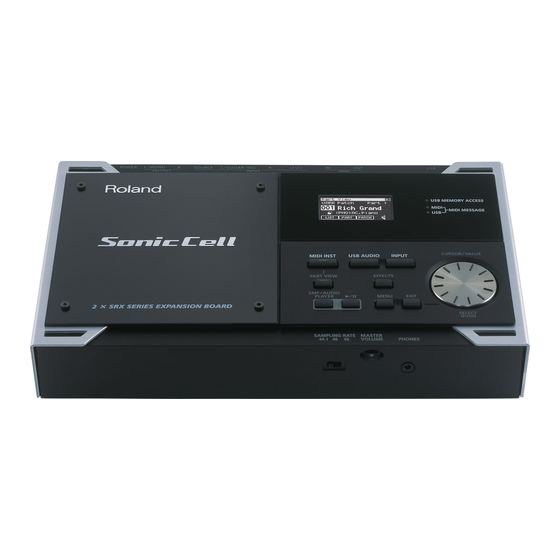
USER‘S GUIDE Top Panel fig.kakubu-topPanel.eps USB MEMORY ACCESS Indicator This will light when you’re playing song data from USB memory that's connected to the SonicCell, or when you're saving data to USB memory. Display Various information is shown MIDI MESSAGE Indicator here according to your operations. -
Page 15: Playing The Demo Songs
Press this button when you Press this button when you apply an effect to the signal from a want to use the SonicCell as want to apply an effect to the device connected to the INPUT jack, a MIDI sound module. -
Page 16: Rear And Front Panels
This specifies the sampling rate used to record or play back audio data. This adjusts the volume of the After changing this setting, you’ll need to turn the SonicCell’s power off, signals output from the PHONES then on again. If you’re using software, you’ll also need to restart your software. - Page 17 These jacks output the combined signals of the sound received from INPUT, the sound from the USB-connected computer, and the sound from the SonicCell itself. LINE (R) Jack When using LINE (L) and LINE (R) for stereo input, input the signal for the R channel here.
-
Page 18: Turning The Power On/Off
■ Connecting the AC Adaptor Make sure that the [POWER] switch is off. Connect the included power cord to the included AC adaptor. Connect the AC adaptor to the SonicCell’s DC IN connector, and plug the power cord into an AC outlet. fig.AC-setsuzoku.eps DC IN Place the AC adaptor so that its lamp light is on the top side. -
Page 19: Turning The Power On
Front Panel MASTER VOLUME Knob ■ Turning the Power Off Minimize the volume of the SonicCell and of your connected audio equipment. Turn off the power of your connected audio equipment. Turn off the [POWER] switch. The indications in the display will disappear, and the power will turn off. -
Page 20: Basic Operation Of The Soniccell
Basic Operation of the SonicCell USER‘S GUIDE About the display and [CURSOR/VALUE] We’ll explain this using the Performance mode Part View screen as an example. fig.display-sample.eps. Accessing the Part View Screen the Name of After turning the power on, make sure that [MIDI the display INST] is lit, then press [PART VIEW]. -
Page 21: Editing A Value
Basic Operation of the SonicCell Editing a Value fig.dispCursorValue1 Let’s try changing the patch number. Patch Number Turn [CURSOR/VALUE] to move the cursor to the patch number. Cursor fig.cursor-push-eps Press [CURSOR/VALUE]. Press fig.dispCursorValue2 fig.cursor-turn.eps The patch number will be highlighted. -
Page 22: Using The Soniccell As A Midi Sound Module
(INPUT) may be low. If this happens, use connection cables that do not contain resistors. ■ Performance mode and Patch mode When using the SonicCell as a MIDI sound module, either Performance mode or Patch mode can be selected. -
Page 23: Playing The Soniccell In Patch Mode
Using the SonicCell as a MIDI Sound Module Playing the SonicCell in Patch Mode ■ Selecting Patch Mode fig.button-MIDI-PART.eps/fig.disp-PatchPlay.eps In the MIDI INST screen, simultaneously press [MIDI INST] and [PART VIEW]. The SonicCell will enter Patch mode, and the Patch Play screen will appear. -
Page 24: Modifying The Sound (Editing A Patch)
USER‘S GUIDE Example: Selecting “037 Violin” from the “PR-C” group fig.dispPtchSlct01.eps Patch Group In the Patch Play screen, turn [CURSOR/VALUE] to move the cursor to the patch group. Press [CURSOR/VALUE]. fig.dispPtchSlct02.eps Turn [CURSOR/VALUE] to select “PR-C,” then press [CURSOR/ VALUE]. fig.dispPtchSlct03.eps Turn [CURSOR/VALUE] to move the cursor to the patch num- ber, then press [CURSOR/VALUE]. -
Page 25: Adjusting The Release
Using the SonicCell as a MIDI Sound Module Adjusting the Attack fig.dispTVAEnv.eps Turn [CURSOR/VALUE] to move the cursor to “A-Env Time1.” Press [CURSOR/VALUE]. The value will be highlighted. Turn [CURSOR/VALUE] to change the value, then press [CUR- T1(when you press a key) SOR/VALUE]. - Page 26 USER‘S GUIDE ■ Editing the Filter By editing the filter settings you can make the tonal character of the sound brighter or darker. fig.dispPtchPly-Edithanten.eps In the Patch Play screen, turn [CURSOR/VALUE] to move the cur- sor to the “EDIT.” Press [CURSOR/VALUE]. The Patch Edit screen will appear.
-
Page 27: Using The Editor And Librarian
Dedicated editor and librarian software is included with the SonicCell. By using the editor you can edit the SonicCell’s performance and patch parameters on your computer. You can edit the settings while viewing them in the large screen of your computer. -
Page 28: Playing Songs (Portable Backing Machine)
OUTPUT MEMORY Use only USB memory sold by Roland. Operation cannot be guaranteed when products other than there is used. Proper operation cannot be guaranteed if other USB memory products is used. Connect the USB memory after the SonicCell’s power is turned on. - Page 29 In this case, move the sampling rate switch to the rate of the song you want to play, then turn the SonicCell’s power off, then on again. Change the setting of the [SAMPLING RATE] switch. Switch off the SonicCell’s power, then turn it back on.
-
Page 30: Creating A Playlist
You can use the included “SonicCell Playlist Editor” to create a playlist for playback by the SonicCell. If you want to use the SonicCell to play backing tracks, it’s convenient to create a playlist in the order you want the songs to play. -
Page 31: Connecting The Soniccell To Your Computer
Connecting the SonicCell to Your Computer You can use the SonicCell as an external sound module for your DAW or sequencer software. NOTE You must install the driver before you connect the SonicCell to your computer. ■ Example Connections and Preparations for Installation fig.setsuzoku-DAW.eps... -
Page 32: Specifications Of The Dedicated Plug-In Version Of The Editor
*Although Roland has tested numerous configurations, and has determined that on average, a computer system similar to that described above will permit normal operation of the SonicCell Applications, Roland cannot guarantee that a given computer can be used satisfactorily with the SonicCell Applications based solely on the fact that it meets the left requirements. -
Page 33: Windows Xp Users
For details, ask the system administrator of your computer. NOTE On the SonicCell Editor CD, the XP folder located inside the Driver folder contains a Readme file (Readme_E.html), which explains how to install the driver and includes a number of trouble- shooting tips. -
Page 34: Windows Settings
Start up Windows Media Player, play back an audio file and a MIDI file, and verify that you hear the sound correctly. Installing SonicCell Editor Insert the “SonicCell Driver CD-ROM” into your CD-ROM drive, navigate to the Editor folder, and double-click Setup.exe. The “Welcome” screen will appear. Click [Next]. -
Page 35: Windows Vista Users
Close all applications. Also close any anti-virus or system-monitoring software. Place the “SonicCell Editor CD” into your CD-ROM drive, navigate to the Driver folder | Vista folder, and double-click Setup.exe. * If the message “Drivers must be installed by an administrator user.” is displayed, log on to Windows as a user whose account type is Administrator, and then perform the installation again. -
Page 36: Windows Settings
Start up Windows Media Player, play back an audio file, and verify that sound is produced cor- rectly. Installing SonicCell Editor Insert the “SonicCell Editor CD-ROM” into your CD-ROM drive, navigate to the Editor folder, and double-click Setup.exe. The screen will indicate “An unidentified program is requesting access to this computer”; click [Allow]. -
Page 37: Mac Os X Users
If an “Authentication” dialog box appears during the installation, enter your password and click [OK]. Start up your computer with all USB cables disconnected (except for the keyboard and mouse). Insert the “SonicCell Editor CD-ROM” into your CD-ROM drive, navigate to the Driver folder, and double-click “SonicCellUSBDriver.pkg.”... -
Page 38: Installing Soniccell Editor
You’ll need Adobe Reader (available free of charge) in order to view PDF files. Settings ■ Mac OS X Audio Input/Output Settings Use a USB cable to connect the SonicCell to your computer, then switch on the SonicCell’s power. In “System Preference,” click “Sounds.” Choose “Roland SonicCell ** kHz” for the following settings. - Page 39 In the “Audio MIDI Setup” dialog box, verify that “SonicCell” is shown. * If “SonicCell” is not shown, or if it is shown grayed-out, the SonicCell was not detected correctly. Try clicking “Re-scan MIDI.” You can also try switching off the SonicCell’s power, then turning it back on.
-
Page 40: Recording A Mic Or Guitar(Usb/Audio Interface)
Recording a Mic or Guitar USER‘S GUIDE (USB/Audio Interface) ■ Connections fig.setsuzoku-Input.eps Acoustic Guitar etc. Guitar Dynamic Mic Computer To USB Connector Keyboard of Computer Condenser Mic USB cable Monitor Amplifier etc. LINE (R) INPUT OUTPUT USB COMPUTER Set the INPUT LEVEL knob to “MIN” before making connections NOTE To prevent malfunction and/or damage to speakers or other devices, always turn down the vol-... -
Page 41: Connecting A Mic
Settings Required Guitar INPUT SOURCE switch When sending your guitar through an effects unit before connecting it to the SonicCell ➝ Set to “LINE” When connecting your guitar directly to the SonicCell without passing through an effects unit ➝ Set to “GUITAR”... -
Page 42: Using The Line Input
USER‘S GUIDE Using the Line Input fig.setsuzoku-input-Line.eps Keyboard Settings Required INPUT SOURCE switch ➝ Set to “LINE” OUTPUT If you’re inputting in mono (one cable) ➝ Connect to L (MONO) If you want to apply an effect ➝ Refer to p. 144 LINE (R) L/GUITAR/MIC Input Source... -
Page 43: Input Effect Settings
If you want to apply an effect to the sound from the Input jack, change the settings as appropriate for your situation. ■ Sending the Same Sound as Heard From the Speakers to Your Computer Input-b.eps Monitor Amplifier etc. SonicCell Reverb, Patch, Performance Chorus, Mastering... - Page 44 • Reverb Send Level ➝ p. 148 • Mastering Effect ➝ p. 181 ■ Applying an effect such as reverb to the sound heard from the speakers, while recording the unprocessed sound to your computer Input-a.eps Monitor Amplifier etc. SonicCell Reverb, Patch, Performance Chorus, Mastering Effect...
- Page 45 Recording a Mic or Guitar (USB/Audio Interface) Change the value to “To Input FX.” For more about the Input “Assign” setting ➝ p. 142 To select the type of input effect ➝ p. 147 To adjust the depth of chorus or reverb ➝ p. 148 fig.disp-InOutRouting.epsfig.disp-InOutRouting-ToCom.eps Setting the Output to Computer Press [EFFECT] to access the In/Out Routing screen.
-
Page 46: Installing The Wave Expansion Board
● When installing Wave Expansion Boards, remove only the specified screws. ● Be careful that the screws you remove do not drop into the interior of the SonicCell. ● Do not leave the cover removed. After installation of the Wave Expansion Boards is complete, be sure to replace the cover. -
Page 47: How To Install A Wave Expansion Board
EXP A-EXP B slots. These slots correspond with the Wave Expansion Board groups (XP-A-XP-B) when the expansion Wave, patches, and rhythm sets are used. Before installing the Wave Expansion Board, turn off the power of the SonicCell and all con- nected devices, and disconnect all cables, including the Power cable, from the SonicCell. -
Page 48: Checking The Installed Wave Expansion Boards
USER‘S GUIDE Checking the Installed Wave Expansion Boards After installation of the Wave Expansion Boards has been completed, check to confirm that the installed boards are being recognized correctly. Turn on the power, as described in “Turning the Power On” (p. 19 ). fig.disp-Menu-left-Snd.eps Press [MENU]. -
Page 49: Installation De La Carte D'extension Wave (French Language For Canadian Safety Standard)
Deux cartes d’expansion Wave (serie SRX; vendues separement) peuvent etre installees dans le SonicCell. Les donnees Waveform, les retouches et les groupes de rythme sont stockes sur la carte d’expansion Wave; vous pouvez donc augmenter le nombre de sons disponibles en installant la carte dans le SonicCell. NOTE Installer une carte d’expansion Wave augmente les retouches et les groupes de percussion... -
Page 50: Installation D'une Carte D'expansion Wave
Wave (XP-A- XP-B) lorsque l’expansion Wave, les correctifs et rythmes sont utilises. Avant d’installer la carte d’expansion Wave, coupez l’alimentation du SonicCell et de tous les appareils branches, et debranchez tous les cables du SonicCell, y compris le cable d’alimenta- tion. -
Page 51: Verification Des Cartes D'extension Audio Apres Installation
Installation de la carte d’extension Wave (French language for Canadian Safety Standard) Verification des cartes d’extension audio apres installation Lorsque l’installation des cartes d’extension audio est terminee, proceder a une verification pour s’assurer que l’ordinateur les identifie correctement. Mettre sous tension de la facon decrite sous “Turning the Power On” (p. 19 ). fig.disp-Menu-left-Snd.eps Appuyer sur [MENU]. - Page 52 MEMO...
-
Page 53: Midi Sound Module
MIDI Sound Module... -
Page 54: Overview
Overview You can use the SonicCell as a MIDI sound module in either of two modes: Performance mode or Patch mode. Performance Mode and Patch Mode ■ Performance mode ■ Part In Performance mode you can use multiple patches or rhythm On the SonicCell, a “part”... -
Page 55: How A Rhythm Set Is Structured
Specifies the PCM waveform (wave) that is the basis of the Used sound, and determines how the pitch of the sound will change. The SonicCell is able to play up to 128 notes simultaneously. TVF (Time Variant Filter) The polyphony, or the number of voices (sounds) does not... -
Page 56: About The Effects
This is a stereo compressor (limiter) that is applied to the final level to be sent to each effects unit (Send Level) provides output of the SonicCell. It has independent high, mid, and low control over the effect intensity that’s applied to each tone. -
Page 57: About Memory
This is the area that holds the data for the patch or rewritable, and non-rewritable. performance that you’ve selected using the panel buttons. When you play the SonicCell, sound is produced based on USB Memory data in the temporary area. When you edit a patch or Song performance, you do not directly modify the data in memory;... -
Page 58: Using The Soniccell In Performance Mode
Selects the one part that will be heard. Parts other than the one set to -, M, S, * part “S” will be muted. In the SonicCell Editor you can set mute and solo separately. In this case, “*” is shown for parts for which both mute and solo have been specified. -
Page 59: Viewing The Menu Screen (Performance Menu Screen)
Using the SonicCell in Performance Mode Viewing the menu screen (Performance Menu screen) 1. Press [MIDI INST] so its indicator is lit. The MIDI INST screen will appear. 2. Press [MENU]. The Performance Menu screen will appear. The Performance Menu screen has the structure shown in the illustration at right. -
Page 60: Switching The Sound Mode (Sound Mode Screen)
Using the SonicCell in Performance Mode Switching the sound mode (Sound Mode screen) This specifies the mode of the MIDI sound generator. 1. Turn [CURSOR/VALUE] to move the cursor, and press [CURSOR/VALUE] to confirm your choice of mode. The current mode is highlighted. -
Page 61: Menu Screen
Using the SonicCell in Performance Mode Parameter Value Explanation Determines, on an individual MIDI channel basis, whether MIDI modulation _, O (Receive Modulation Switch) messages will be received (O) or not received (_). Determines, on an individual MIDI channel basis, whether MIDI volume mes-... -
Page 62: Viewing The Part Settings (Part View Screen)
Using the SonicCell in Performance Mode Viewing the part settings (Part View screen) 1. Press [MIDI INST] so its indicator is lit. fig.disp-PartView-01 The MIDI INST screen will appear. 2. Move the cursor to the part that you want to edit, and press [PART VIEW]. -
Page 63: Patch Category
Using the SonicCell in Performance Mode ■ Patch Category Category Contents - - - No Assign No assign AC.Piano Acoustic Piano EL.Piano Electric Piano Keyboards Other Keyboards (Clav, Harpsichord etc.) Bell Bell, Bell Pad Mallet Mallet Organ Electric and Church Organ... -
Page 64: If The Patch Type Is Rhythm Set
Using the SonicCell in Performance Mode If the patch type is Rhythm Set If in Performance mode you’ve set the current part’s patch type to “Rhythm,” the following screen will appear. fig.disp-PartView-r ( 1 ) ( 2 ) ( 3 ) -
Page 65: Selecting Patches From A Patch List By Category (Patch List (Ctg) Screen)
Using the SonicCell in Performance Mode Selecting patches from a patch list by category (Patch List (Ctg) screen) You can choose the patch for each part from a list that’s arranged by category. * When the power is turned on, the Patch List (Ctg) screen is selected. -
Page 66: Selecting Patches From A Patch List By Group (Patch List (Grp) Screen)
Using the SonicCell in Performance Mode Selecting patches from a patch list by group (Patch List (Grp) screen) You can choose the patch for each part from a list that’s arranged by group, such as USER or expansion board. * When the power is turned on, the Patch List (Ctg) screen is selected. -
Page 67: Selecting A Rhythm Set From A List (Rhythm Set List Screen)
Using the SonicCell in Performance Mode Selecting a rhythm set from a list (Rhythm Set List screen) If the current part’s patch type is “Rhythm,” you can choose a rhythm set from a list. 1. Press [MIDI INST] so its indicator is lit. -
Page 68: Editing Parts (Part Edit Screen)
Using the SonicCell in Performance Mode Editing parts (Part Edit screen) 1. Press [MIDI INST] so its indicator is lit. fig.disp-PartEdit01 The MIDI INST screen will appear. 2. Move the cursor to the part that you want to edit, and press [PART VIEW]. -
Page 69: Part Edit Screen
Using the SonicCell in Performance Mode ■ Part Edit screen ......................Parameter Value Explanation Adjust the volume of each part. Level 0–127 This setting’s main purpose is to adjust the volume balance between parts. Adjust the pan of each part. - Page 70 Using the SonicCell in Performance Mode Parameter Value Explanation Adjusts the Resonance for the patch or rhythm set assigned to a part. Patches also have a Resonance Offset setting (p. 91). The final Resonance value is Resonance Offset -64–+63 the sum of the tone Resonance value and the patch and part Resonance Offset values.
- Page 71 Tones in the Patches you‘re using and the number of keys being pressed. For example, if you play one note using a Patch that consists of only one Tone, you’ll use up one voice of polyphony. SonicCell Tones may use two Waveforms. If a Voice Reserve 0–63, FULL Patch’s Tone uses two Waveforms, the number of voices it requires is doubled.
-
Page 72: Scale Tune Settings (Scale Tune Screen)
Receive Switch OFF, ON For each part, specify whether MIDI messages will be received (ON), or not (OFF). The SonicCell allows you to use temperaments other than equal temperament. Scale Tune OFF, ON Press [CURSOR/VALUE] to access the Scale Tune screen (p. 72). -
Page 73: Sound Control Initialize
Using the SonicCell in Performance Mode Sound Control Initialize Performance Write Initializes the values of only the following sound-related Saves the current performance as user data. parameters for the current performance. When you select “Write” from the Performance Menu screen (p. - Page 74 Using the SonicCell in Performance Mode 5. Turn [CURSOR/VALUE] to select the save-destination performance, then press [CURSOR/VALUE]. A confirmation message will appear. 6. To write the performance into memory, select “OK” and press [CURSOR/VALUE]. If you decide you don’t want to carry out the write, select “CANCEL”...
-
Page 75: Editing Effects
Using the SonicCell in Performance Mode Editing effects In Performance mode you can use three multi-effects (MFX1, MFX2, MFX3), one chorus, and one reverb. For each of the three multi- effects, the chorus, and the reverb, you can specify whether it will operate according to the effect settings of the performance, or according to the effect settings of the patch or rhythm set assigned to the part you specify. - Page 76 Using the SonicCell in Performance Mode ■ Procedure ........................1. From the MIDI INST screen or the Part View screen, press [EFFECTS]. The [EFFECTS] indicator will light, and the Effect Routing screen will appear. fig.disp-PerformEfxSW01 4. Turn [CURSOR/VALUE] to move the cursor to the parameter that you want to edit.
-
Page 77: Selecting The Item To Edit (Effect Routing Screen)
Using the SonicCell in Performance Mode Selecting the item to edit (Effect Routing screen) Parameter Explanation Edits the part settings. Part By moving the cursor to and pressing [CURSOR/VALUE] you can move to the Part Edit screen (Part Output) (p. 69). -
Page 78: Editing The Multi-Effects Related Settings (Mfx1-3/Mfx1-3 Output Screens)
Using the SonicCell in Performance Mode Editing the multi-effects related settings (MFX1–3/MFX1–3 Output screens) ■ MFX1–3 screens ......................Parameter Value Explanation 00: THRU–78: SYMRESONANCE Selects the types of multi-effects that MFX1--MFX3 will use. (MFX Type) Choose “00: THRU” if you don’t want to apply a multi-effect. -
Page 79: Reverb-Related Settings (Reverb/Reverb Output Screen)
Using the SonicCell in Performance Mode ■ Chorus Output screen ....................Parameter Value Explanation Output Level 0–127 Adjusts the volume of the sound that has passed through chorus. Specifies how the sound routed through chorus will be output. MAIN: Output to the OUTPUT jacks in stereo. -
Page 80: Changing How The Multi-Effects Are Combined (Mfx Structure Screen)
Using the SonicCell in Performance Mode Changing how the multi-effects are combined (MFX Structure screen) Parameter Value Explanation TYPE01– MFX Structure Specify how MFX1–3 will be connected. TYPE16 Selecting how effects will operate (Effect Source screen) Parameter Value Explanation Selects the MFX1 settings that will be used by the performance. -
Page 81: Using Midi To Control The Multi-Effects (Mfx1-3 Control Screens)
For that reason, a number of the more typical of the SonicCell’s multi-effects parameters have been designed so they accept the use of Control Change (or other) MIDI messages for the purpose of making changes in their values. -
Page 82: Using The Soniccell In Patch Mode
Using the SonicCell in Patch Mode Viewing the Patch Play screen 1. Press [MIDI INST] so its indicator is lit. 2. Turn [CURSOR/VALUE] to move the cursor to the parameter you want to edit. At the same time, the [PART VIEW] indicator will also light, and the Patch Play screen will appear. -
Page 83: If The Patch Type Is Rhythm Set
Using the SonicCell in Patch Mode If the patch type is Rhythm Set If in Patch mode you’ve set the current patch type to “Rhythm,” the following screen will appear. fig.disp-PatchPlay-r ( 1 ) ( 2 ) ( 3 ) -
Page 84: Viewing The Menu Screen (Patch Menu Screen)
Using the SonicCell in Patch Mode Viewing the menu screen (Patch Menu screen) 1. Press [MIDI INST] so its indicator is lit. The Patch Play screen will appear. If the Sound Mode is set to “Performance,” the MIDI INST screen (p. 58) will appear. -
Page 85: Selecting Patches From A Patch List
Using the SonicCell in Patch Mode Selecting patches from a patch list Selecting patches from a patch list by category (Patch List (Ctg) screen) You can choose the patch from a list that’s arranged by category. * When the power is turned on, the Patch List (Ctg) screen is selected. -
Page 86: Selecting Patches From A Patch List By Group (Patch List (Grp) Screen)
Using the SonicCell in Patch Mode Selecting patches from a patch list by group (Patch List (Grp) screen) You can choose the patch from a list that’s arranged by group, such as USER or expansion board. * When the power is turned on, the Patch List (Ctg) screen is selected. -
Page 87: Selecting A Rhythm Set From A List (Rhythm Set List Screen)
Using the SonicCell in Patch Mode Selecting a rhythm set from a list (Rhythm Set List screen) If the patch type is “Rhythm,” you can choose a rhythm set from a list. 1. Display the Patch Play screen. 3. Turn [CURSOR/VALUE] to select a rhythm set, and press [CURSOR/VALUE]. -
Page 88: Editing Patches (Patch Edit Screen)
Using the SonicCell in Patch Mode Editing patches (Patch Edit screen) 1. Press [MIDI INST]. 3. Turn [CURSOR/VALUE] to select the item you want to edit, then press [CURSOR/VALUE]. [MIDI INST] and [PART VIEW] will light, and the Patch The editing screen for the selected item will appear. -
Page 89: Patch Edit Screen
Using the SonicCell in Patch Mode ■ Patch Edit screen ......................The Patch Edit screen is organized as follows. You can turn [CURSOR/VALUE] to the right or left to switch between screens. Parameter Value Explanation Edits overall settings for the entire patch. -
Page 90: Overall Settings For The Entire Patch (Patch General Screen)
Using the SonicCell in Patch Mode Overall settings for the entire patch (Patch General screen) Parameter Value Explanation refer to “Patch Specifies the type (category) of the patch. (Category) Category” (p. 63) Specifies the volume of the Patch. Level 0–127 * You can specify the level of each Tone in a Patch using the Tone Level (TVA p. - Page 91 Using the SonicCell in Patch Mode Parameter Value Explanation Resonance Offset alters the resonance of the overall patch, while preserving the relative dif- ferences between the resonance values set for each tone in the Resonance (p. 103). * Resonance: emphasizes the overtones in the region of the cutoff frequency, adding char- Resonance acter to the sound.
- Page 92 Using the SonicCell in Patch Mode Parameter Value Explanation Specifies whether the portamento effect will be applied (ON) or not (OFF). Porta Sw * Portamento is an effect which smoothly changes the pitch from the first-played key to the (Portamento OFF, ON next-played key.
-
Page 93: Selecting How Tones Are Combined (Patch Structure Screen)
Ring Modulator Str (Structure) Type 1&2, 3&4 1–10 When TYPE05–TYPE10 is selected, the SonicCell can play a maximum of 64 sounds simultaneously. When a Structure Type of TYPE 3 or TYPE 4 is selected, you can adjust the Booster 1&2, 3&4 0, +6, +12, +18 depth of the booster. - Page 94 Using the SonicCell in Patch Mode Parameter Value Explanation Type 7 This type applies a filter to tone 1 (3) and ring-modulates it with tone 2 (4) to create new overtones. TONE 1 (3) TONE 2 (4) Type 8 This type sends the filtered tone 1 (3) and tone 2 (4) through a ring modulator, and then mixes in the sound of tone 2 (4) and applies a filter to the result.
-
Page 95: Settings For Matrix Control (Patch Mtrx Ctrl1-4 Screens)
For that reason, a number of the more typical of the SonicCell’s tone parameters have been designed so they accept the use of Control Change (or other) MIDI messages for the purpose of making changes in their values. This provides you with a variety of means of changing the way patches are played. - Page 96 Using the SonicCell in Patch Mode Parameter Value Explanation Matrix Control Destination selects the tone parameter that is to be controlled when using the Matrix Control. The following parameters can be controlled. When not controlling parameters with the Ma- trix Control, set this to “OFF.” Up to four parameters can be specified for each Matrix Control, and controlled simultaneously.
-
Page 97: Cautions When Selecting A Waveform
Cautions When Using a One-shot Waveform It is not possible to use the envelope to modify a one-shot waveform The sounds of the SonicCell are based on complex PCM waveforms, to create a decay that is longer than the original waveform, or to turn and if you attempt to make settings that are contrary to the type of the it into a sustaining sound. -
Page 98: Waveform-Related Settings (Patch Wg/Patch Pitch Env Screen)
Using the SonicCell in Patch Mode Waveform-related settings (Patch WG/Patch Pitch Env screen) ■ Patch WG screen ......................Parameter Value Explanation Selects the group for the waveform that is to be the basis of the tone. INT: Waveforms stored in internal memory... - Page 99 Using the SonicCell in Patch Mode Parameter Value Explanation Specifies how FXM will perform frequency modulation. FXM Color 1–4 Higher settings result in a grainier sound, while lower settings result in a more metallic sound. Specifies the depth of the modulation produced by FXM.
- Page 100 Using the SonicCell in Patch Mode Parameter Value Explanation Specifies the time from when the key is pressed (or if the Delay Mode pa- rameter is set to “OFF-N” or “OFF-D,” the time from when the key is re- leased) until when the tone will sound.
-
Page 101: Patch Pitch Env Screen
Using the SonicCell in Patch Mode ■ Patch Pitch Env screen....................Parameter Value Explanation Adjusts the effect of the Pitch Envelope. Higher settings will cause the pitch P-Env Depth -12–+12 envelope to produce greater change. Negative (-) settings will invert the (Pitch Envelope Depth) shape of the envelope. -
Page 102: Tvf Settings (Patch Tvf/Patch Tvf Env Screen)
Using the SonicCell in Patch Mode Parameter Value Explanation Specify the pitch envelope levels (Level 0–Level 4). It determines how much the pitch changes from the reference pitch (the value set with Coarse Tune P-Env Level 0–4 -63–+63 or Fine Tune on the Pitch screen) at each point. Positive (+) settings will cause (Pitch Envelope Level 0–4) - Page 103 Using the SonicCell in Patch Mode Parameter Value Explanation Emphasizes the portion of the sound in the region of the cutoff frequency, adding character to the sound. Excessively high settings can produce oscillation, causing the sound to distort. To edit the overall patch while preserving the relative differences in the Resonance values set for each tone, set the Resonance Offset (p.
-
Page 104: Patch Tvf Env Screen
Using the SonicCell in Patch Mode ■ Patch TVF Env screen ....................Parameter Value Explanation Specifies the depth of the TVF envelope. Higher settings will cause the TVF F-Env Depth -63–+63 envelope to produce greater change. Negative (-) settings will invert the (TVF Envelope Depth) shape of the envelope. -
Page 105: Tva Settings (Patch Tva/Patch Tva Env Screen)
Using the SonicCell in Patch Mode Parameter Value Explanation Specify the TVF envelope times (Time 1–Time 4). Higher settings will length- en the time until the next cutoff frequency level is reached. (For example, Time 2 is the time over which Level 1 will change to Level 2.) F-Env Time1–4 ★... - Page 106 Using the SonicCell in Patch Mode Parameter Value Explanation Selects the direction in which change will occur starting from the Bias Posi- tion. LOWER: The volume will be modified for the keyboard area below the Bias Point. LOWER, UPPER, UPPER:...
-
Page 107: Patch Tva Env Screen
Using the SonicCell in Patch Mode ■ Patch TVA Env screen....................Parameter Value Explanation This allows keyboard dynamics to affect the Time 1 of the TVA envelope. If A-Env T1 V-Sens you want Time 1 to be speeded up for strongly played notes, set this param- (TVA Envelope Time 1 Velocity -63–+63... -
Page 108: Patch/Tone Output-Related Settings (Patch Output Screen)
Using the SonicCell in Patch Mode Patch/Tone output-related settings (Patch Output screen) Parameter Value Explanation Specifies how the direct sound of each patch will be output. MFX: Output in stereo through multi-effects. You can also apply chorus or reverb to the sound that passes through multi-effects. -
Page 109: Lfo Settings (Patch Lfo1, 2/Patch Step Lfo Screen)
Using the SonicCell in Patch Mode LFO settings (Patch LFO1, 2/Patch Step LFO screen) ■ Patch LFO1, 2 screens....................An LFO (Low Frequency Oscillator) causes change over a cycle in a sound. Each tone has two LFOs (LFO1/LFO2), and these can be used to cyclically change the pitch, cutoff frequency and volume to create modulation-type effects such as vibrato, wah and tremolo. - Page 110 Using the SonicCell in Patch Mode Parameter Value Explanation Delay Time (LFO Delay Time) specifies the time elapsed before the LFO effect is applied (the effect continues) after the key is pressed (or released). When using violin, wind, or certain other instrument sounds in a...
- Page 111 Using the SonicCell in Patch Mode Parameter Value Explanation How to Apply the LFO ● Apply the LFO gradually after the key is pressed ● Apply the LFO immediately when the key is pressed, and then gradually begin to decrease the effect Fade Mode: ON <...
-
Page 112: Specifies How The Tones Will Be Heard (Patch Tmt Screen)
Using the SonicCell in Patch Mode ■ Patch Step LFO screen....................Parameter Value Explanation When generating an LFO waveform from the data specified in LFO Step1– Step Type TYP1, TYP2 16, specify whether the level will change abruptly at each step (TYP1) or will be connected linearly (TYP2). - Page 113 Using the SonicCell in Patch Mode Parameter Value Explanation Specifies the highest note that the tone will sound for each tone. Key (Keyboard) Range Upper Lower–G9 If you attempt to raise the lower key higher than the upper key, or to lower the upper key below the lower key, the other value will be automatically modified to the same setting.
-
Page 114: Controller-Related Settings (Patch Ctrl Screen)
Using the SonicCell in Patch Mode Controller-related settings (Patch Ctrl screen) Parameter Value Explanation When a loop waveform (p. 97) is selected, the sound will normally continue as long as the key is pressed. If you want the sound to decay naturally even if the key remains pressed, set this to “NO-SUS.”... -
Page 115: Tone Copy
Using the SonicCell in Patch Mode Tone Copy Patch Initialize This operation copies tone settings from a patch to one of the Returns the current patch settings to their initial values. tones in the currently selected patch. From the Patch Edit menu screen (p. 88), select “Patch Init.”... -
Page 116: Patch Write
Using the SonicCell in Patch Mode 5. Turn [CURSOR/VALUE] to select the save-destination Patch Write patch, then press [CURSOR/VALUE]. A confirmation message will appear. Saves the current patch as user data. From the Patch Edit menu screen (p. 88), select “Write” to access the Patch Name screen. -
Page 117: Editing Rhythm Sets (Rhythm Edit Screen)
Using the SonicCell in Patch Mode Editing rhythm sets (Rhythm Edit screen) 1. Press [MIDI INST]. 3. Turn [CURSOR/VALUE] to select the item you want to edit, then press [CURSOR/VALUE]. [MIDI INST] and [PART VIEW] will light, and the Patch The editing screen for the selected item will appear. -
Page 118: Edits Overall Settings For The Entire Rhythm Set (Rhythm General Screen)
Using the SonicCell in Patch Mode ■ Rhythm Edit screen ....................... Parameter Explanation Edits overall settings for the entire rhythm set. General Press [CURSOR/VALUE] to access the Rhythm General screen. Edits waveform-related settings. Press [CURSOR/VALUE] to access the Rhythm Wave screen (p. 120). - Page 119 Using the SonicCell in Patch Mode Parameter Value Explanation On an actual acoustic drum set, an open hi-hat and a closed hi-hat sound can never occur simultaneously. To reproduce the reality of this situation, you can set up a Mute Group.
-
Page 120: Waveform-Related Settings (Rhythm Wave Screen)
Wave No. L (MONO) This selects the Waves comprising the rhythm tone. You can choose a sep- arate waveform for the SonicCell’s left and right channels. * For mono tones, assign a waveform to the L channel. No sound will be 1–1401... - Page 121 Using the SonicCell in Patch Mode Parameter Value Explanation Specifies the depth of the modulation produced by FXM. FXM Depth 0–16 When the Tempo Sync is set to “ON,” settings related to Pitch (p. 122) and FXM are disabled. Adjusts the pitch of the waveform’s sound up or down in semitone steps (+/ -4 octaves).
-
Page 122: Specifying How A Rhythm Tone Will Be Heard (Rhythm Wmt Screen)
Using the SonicCell in Patch Mode Specifying how a rhythm tone will be heard (Rhythm WMT screen) You can use your keyboard playing dynamics to control the four waveforms assigned to the rhythm tone. These settings are collectively called the “Wave Mix Table (WMT).”... -
Page 123: Rhythm Pch Env Screen
Using the SonicCell in Patch Mode Parameter Value Explanation Adjusts the pitch of the rhythm tone’s sound up or down in 1-cent steps (+/ -50 cents). * One cent is 1/100th of a semitone. Tone Fine Tune -50–+50 (Rhythm Tone Fine Tune) Set the fine tuning for Waves comprising the rhythm tones with the Wave Fine Tune (p. -
Page 124: Tvf Settings (Rhythm Tvf/Rhythm Tvf Env Screen)
Using the SonicCell in Patch Mode TVF settings (Rhythm TVF/Rhythm TVF Env screen) ■ Rhythm TVF screen ....................... Parameter Value Explanation Selects the type of filter. A filter cuts or boosts a specific frequency region to change a sound’s brightness, thickness, or other qualities. - Page 125 Using the SonicCell in Patch Mode Parameter Value Explanation Emphasizes the portion of the sound in the region of the cutoff frequency, adding character to the sound. Excessively high settings can produce oscil- lation, causing the sound to distort. Level...
-
Page 126: Rhythm Tvf Env Screen
Using the SonicCell in Patch Mode ■ Rhythm TVF Env screen ....................Parameter Value Explanation Specifies the depth of the TVF envelope. Higher settings will cause the TVF F-Env Depth -63–+63 envelope to produce greater change. Negative (-) settings will invert the (TVF Envelope Depth) shape of the envelope. -
Page 127: Tva Settings (Rhythm Tva/Rhythm Tva Env Screen)
Using the SonicCell in Patch Mode TVA settings (Rhythm TVA/Rhythm TVA Env screen) ■ Rhythm TVA screen....................... Parameter Value Explanation Sets the volume of the rhythm tone. This setting is useful primarily for adjust- ing the volume balance between rhythm tones. -
Page 128: Rhythm Tva Env Screen
Using the SonicCell in Patch Mode ■ Rhythm TVA Env screen ....................Parameter Value Explanation This allows keyboard dynamics to affect the Time 1 of the TVA envelope. If A-Env T1 V-Sens you want Time 1 to be speeded up for strongly played notes, set this param- (TVA Envelope Time 1 Velocity -63–+63... -
Page 129: Output-Related Settings For The Rhythm Set And Rhythm Tones (Rhythm Output Screen)
Using the SonicCell in Patch Mode Output-related settings for the rhythm set and rhythm tones (Rhythm Output screen) Parameter Value Explanation Specifies for each rhythm set how the direct sound will be output. MFX: Output in stereo through multi-effects. You can also apply chorus or reverb to the sound that passes through multi-effects. -
Page 130: Rhythm Tone Copy
Using the SonicCell in Patch Mode Rhythm Tone Copy Rhythm Tone Initialize Copies the settings of a rhythm tone to a rhythm tone in the cur- Returns the settings of just a specific key in the current rhythm rently selected rhythm set. -
Page 131: Rhythm Set Write
Using the SonicCell in Patch Mode 5. Turn [CURSOR/VALUE] to select the save-destination Rhythm Set Write rhythm set, then press [CURSOR/VALUE]. A confirmation message will appear. Saves the current rhythm set as user data. From the Rhythm Edit menu screen (p. 117), select “Write” to access the Rhythm Set Name screen. -
Page 132: Editing The Effects (Patch/Rhythm Set)
Using the SonicCell in Patch Mode Editing the effects (Patch/Rhythm Set) In Patch mode you can use multi-effects, chorus, and reverb. ■ Signal flow........................Tone 4 Tone 3 Tone 2 Patch (Rhythm) Output MFX Output Tone1 Chorus Output MAIN Chorus... - Page 133 Using the SonicCell in Patch Mode ■ Procedure ........................1. In the Patch Edit screen, press [EFFECTS]. 2. Turn [CURSOR/VALUE] to move the cursor to the parameter you want to edit. The [EFFECTS] indicator will light, and the Effect Routing screen will appear.
-
Page 134: Selecting The Item To Edit (Effect Routing Screen)
Using the SonicCell in Patch Mode Selecting the item to edit (Effect Routing screen) Parameter Explanation Edits output-related settings for the patch/tone. Tone (Tone Output) By moving the cursor to and pressing [CURSOR/VALUE] you can move to the Patch Output * Patch Type: Patch screen (p. -
Page 135: Chorus Settings (Chorus/Chorus Output Screens)
Using the SonicCell in Patch Mode ■ MFX Output screen ....................... Parameter Value Explanation Adjusts the volume of the sound that has passed through the multi-effects. If you’re applying a multi-effect, this specifies the depth of the multi-effect. Output Level 0–127... -
Page 136: Reverb Settings (Reverb/Reverb Output Screens)
Using the SonicCell in Patch Mode Reverb settings (Reverb/Reverb Output screens) ■ Reverb screen....................... Parameter Value Explanation 00: OFF–03: GM2 REVERB Selects the types of reverb. (Reverb Type) Choose “00: OFF” if you don’t want to apply a reverb. Edit the parameters for the selected reverb type. -
Page 137: Controlling The Multi-Effects Via Midi (Mfx Control Screen)
For that reason, a number of the more typical of the SonicCell’s multi-effects parameters have been designed so they accept the use of Control Change (or other) MIDI messages for the purpose of making changes in their values. - Page 138 MEMO...
-
Page 139: Audio Connections
Audio Connections... -
Page 140: Using The Soniccell With Your Computer (Usb Audio)
Using the SonicCell with your computer (USB AUDIO) Basic operation 1. Press [USB AUDIO] so its indicator is lit. 3. Press [CURSOR/VALUE] to highlight the value. The USB Audio screen will appear. fig.disp-USB-top01 4. Turn [CURSOR/VALUE] to edit the value. -
Page 141: Accessing The Menu Screen
Using the SonicCell with your computer (USB AUDIO) Accessing the Menu screen From the USB Audio screen, press [MENU] to access the Menu screen. Press [MENU] once again to return to the USB Audio screen. Parameter Explanation Write Saves the current settings as system settings (p. 150). -
Page 142: Inputting Sound From An External Device (Input)
Inputting sound from an external device (INPUT) Basic operation 1. Press [INPUT] so its indicator is lit. fig.disp-Input-top02 The Input screen will appear. fig.disp-Input-top01 4. Turn [CURSOR/VALUE] to edit the value. 5. When you’ve finished editing the value, press [CURSOR/ 2. -
Page 143: Accessing The Menu Screen
Inputting sound from an external device (INPUT) Parameter Value Explanation To Input FX: Sent to the input effect. OUTPUT Input Effect To COM+Output, Assign To COM, To Input FX INPUT Computer Use the “In/Out Routing” (p. 144) to specify how the signal that has passed through the input effect will be output. -
Page 144: Input/Output And Effect Settings (In/Out Routing)
Input/output and effect settings (In/Out Routing) You can specify how the input signal from an external source or USB will be processed by the effects and then output when the [INPUT] or [USB AUDIO] indicator is lit. These settings are called “In/Out Routing.” Here are some examples of what you can do. - Page 145 Input/output and effect settings (In/Out Routing) Listen to the effect-processed sound from your speakers, while recording the unprocessed sound on your computer You can use the chorus/reverb that’s assigned to a performance/patch. In other words, the effect will depend on the performance/ patch that's selected.
- Page 146 Input/output and effect settings (In/Out Routing) ■ Procedure ........................1. Press [INPUT] or [USB AUDIO] so its indicator is lit. 3. Turn [CURSOR/VALUE] to move the cursor to the parameter you want to edit. The Input screen or USB Audio screen will appear. 2.
-
Page 147: Selecting The Item To Edit (In/Out Routing Screen)
Input/output and effect settings (In/Out Routing) Selecting the item to edit (In/Out Routing screen) Parameter Explanation IN FX Edits the input effect settings. (Input Effect) Press [CURSOR/VALUE] to access the Input Effect screen. Edits the output settings for the input effect. By moving the cursor to and pressing [CURSOR/VALUE] you can move to the Input FX (Input Effect output) -
Page 148: Selecting The Signal Sent To Your Computer (To Computer Screen)
Input/output and effect settings (In/Out Routing) ■ Input FX Output screen ....................Parameter Value Explanation Output Level 0–127 Set the level of the signal that is sent to the OUTPUT. Adjusts the amount of chorus for the sound. Chorus Send Level 0–127 If you don’t want to add the Chorus effect, set it to “0.”... -
Page 149: Specifies How Mfx3 Will Be Used (Mfx3 Location Screen)
Specifies how MFX3 will be used (MFX3 Location screen) This screen won’t appear in Patch mode. Parameter Value Explanation Specifies how MFX3 will be used. MFX3 will be used as the effect applied to the SonicCell’s tone generator (TG). MFX1 Tone MFX2 Generator... -
Page 150: System Write
Input/output and effect settings (In/Out Routing) System Write This saves the current system settings. In the menu screen (p. 141, p. 143, p. 146), choose “Write” (System Write) and you'll see a confirmation message. 1. If you want to write the settings, select “OK” and press [CURSOR/VALUE]. -
Page 151: Using The Plug-In Version Of Soniccell Editor
Using the plug-in version of SonicCell Editor This chapter explains how to use the plug-in version of SonicCell Editor as a plug-in module in your VSTi or AU compatible host application. The plug-in version of SonicCell Editor is a plug-in module that lets you edit the SonicCell’s parameters from within your host application. -
Page 152: Sonar Le
Here’s how to install the included SONAR LE into your 1. Close all currently running software. computer. 2. In the SonicCell Editor CD, navigate to the “Sonar In order to perform the following procedure, you’ll need to Utility\VST Adapter updater” folder and double-click log onto Windows as a user whose account type is “VSTAdapter453Update_E.exe”... - Page 153 10. Open the “Drivers” tab. For both “Input Drivers” and “Output Drivers,” click the 2. Click [Add], add “(the folder to which you copied the plug- device names so that only “Roland SonicCell” is in)\Roland,” and then click [Next]. highlighted for each.
- Page 154 SONAR LE Connections and settings Starting up SonicCell Editor 1. Use a USB cable to connect the SonicCell to your computer. 1. Start up SONAR LE. 2. From the menu, choose “File” - “Close” to close the project 2. If necessary, use a MIDI cable to connect your MIDI that was loaded at start-up.
-
Page 155: Selecting A Patch
Here’s how to record your playing. If using Performance mode: If you connect a MIDI keyboard to the SonicCell, you’ll be 1. In the upper part of SonicCell Editor’s main window, click able to record musical data from the keyboard. - Page 156 SonicCell module. If using Patch mode: 1. Close SONAR LE. 2. On the SonicCell module, select a different patch than the one you’re currently using. This is so you can verify that the patch data is reproduced when you open a project.
-
Page 157: Sonar 6.2
“roland” - “SonicCell Editor VST.” 7. If a message indicates “MIDI devices aren’t set up 1. Use a USB cable to connect the SonicCell to your computer. correctly.,” click [OK]. 2. If necessary, use a MIDI cable to connect your MIDI 8. - Page 158 If using Performance mode: Out: SonicCell Controllers 1. In the upper part of SonicCell Editor’s main window, click “PART” [n (number of the part to record)]. You can edit the values by clicking (and dragging) the buttons, 2. In the upper part of SonicCell Editor’s main window, click sliders, and knobs.
- Page 159 SonicCell module. If using Patch mode: 1. Close SONAR 6.2. 2. On the SonicCell module, select a different patch than the one you’re currently using. This is so you can verify that the patch data is reproduced when you open a project.
-
Page 160: Cubase 4
Installing the driver and SonicCell Connections and settings Editor 1. Use a USB cable to connect the SonicCell to your computer. Before you continue, install the driver, SonicCell Editor, 2. If necessary, use a MIDI cable to connect your MIDI Librarian, and Playlist Editor as described on p. - Page 161 Selecting a patch If using Performance mode: 1. Start up Cubase 4. 1. In the upper part of SonicCell Editor’s main window, click 2. From the menu, choose “File” - “New Project” to open the “New Project” dialog box. “PART” [n (number of the part to record)].
- Page 162 This means that if you save your project file, you normally won’t need to save data in SonicCell Editor. 2. On the SonicCell module, select a different patch than the one you’re currently using. 1. From the menu, choose “File” - “Save” to open the “Save This is so you can verify that the patch data is reproduced As”...
-
Page 163: Logic Pro 7.2
8. From the menu that appears, choose “Stereo” - “AU Instruments” - “Roland” - “SonicCell Editor AU.” 1. Use a USB cable to connect the SonicCell to your computer. 9. If a message indicates “MIDI devices aren’t set up correctly.,” click [OK]. - Page 164 9. Select the port. Adding a MIDI track If using Performance mode: In the track “SonicCell n (number of the part to record)” at 1. From the menu, choose “Windows” - “Environment” to the left side of the Arrange window, set the “Port”...
- Page 165 This means that if you save your song file, you normally won’t • Logic Pro 7.2 track “SonicCell n (number of the part to need to save data in SonicCell Editor. record)” corresponds to “Track 1” of the illustration.
- Page 166 MEMO...
-
Page 167: Smf/Audio File Player
USB Memory USB Memory Use only USB memory sold by Roland. Operation cannot be guaranteed when products other than there is used. Proper operation cannot be guaranteed if other USB memory products is used. • Connect the USB memory after the SonicCell’s power is turned on. -
Page 168: Playing Back Songs
• You can’t execute the Write operation or use Utility functions (p. 182) while a song is playing back. • The SonicCell can handle up to a maximum of 99 songs and playlists. (99 items in the root directory, and 99 items inside the SonicCell folder. - Page 169 Playing back songs ( 1 ) ( 2 ) ( 3 ) ( 4 ) ( 6 ) ( 8 ) ( 7 ) ( 5 ) Indication Content Name of the currently playing song SMF: Currently-playing measure, Audio file: Playback time * This is displayed correctly only if you cre- ated the playlist using Playlist Editor.
-
Page 170: Playlist Information Screen
Playing back songs ■ Playlist Information screen .................... Indication Content Name The name of the playlist. Specifies how the song will play. Chain Play If you move the cursor to this item and press [CURSOR/VALUE] to add a check mark (✔), Chain Play will be turned on. -
Page 171: Selecting And Playing A Song From Within A Playlist
A “?” mark is shown if the song’s sampling rate differs 6. Press [ from the setting of the SonicCell module, or if the song is The song will begin playing. not in a file type that the SonicCell can play. This song cannot be played. -
Page 172: Song Information Screen
Playing back songs ■ Song Information screen ....................Indication Content Title Name of the song. Artist Name of the artist. Lets you adjust the volume of the song. Press [CURSOR/VALUE] to access the Song Info (Level) screen. Level Edit * This item is not shown for songs in the USB Memory or Demo Songs playlist. Number of measures in the song (for SMF)/Song length (for an audio file) Meas (Measure)/Time * This item is not shown for songs in the USB Memory or Demo Songs playlist. -
Page 173: Playlist Write
Playing back songs Playlist Write Deleting a song from the playlist Here’s how to write the current playlist settings. Here’s how to delete the currently selected song from the playlist. From the Song Menu screen (p. 171), choose “Write” to access the following screen. - Page 174 MEMO...
-
Page 175: Other Settings
Other Settings... -
Page 176: System Settings
System Settings In the menu screen, choose “SYSTEM” to access the System screen. Here you can make settings for the “system functions,” which affect the operation of the entire SonicCell, such as the tuning, and how MIDI messages are received. - Page 177 Section SonicCell SonicCell USB-MIDI Thru=OFF USB-MIDI Thru=ON This setting allows you to choose the mode that you want the SonicCell to be in when it is powered up. PATCH, Powerup Mode PATCH: The SonicCell will be in Patch mode when you turn on the power.
-
Page 178: Patch Scale Tune Settings
G#, Bb and C#, and Eb and F# have a natural third- the interval between a major third and a minor third. On the SonicCell, you can use Arabian temperament in the three keys of G, C and F. -
Page 179: Settings For The Preview Function (System Preview Screen)
246). System Control System Control settings apply to the entire SonicCell, and specify how MIDI messages will control the volume and sounds. You can specify up to four MIDI messages for control purposes. If you want to make individual settings for each performance, patch, or rhythm set to specify how sounds and effects will be con-... -
Page 180: Midi-Related Settings (System Midi Screen)
From the Menu screen, selecting “SRX Info” will access the System SRX Info screen, where you can view information about the expansion boards connected to the SonicCell. From the MENU screen, selecting “Version” will access the System Version Info screen, where you can view the version of the SonicCell system software. -
Page 181: Editing The Mastering Effect (Mastering Effect Screen)
When you procedure your own original audio CD, this lets you master at an optimized level. Mastering effect settings apply to the entire SonicCell. These settings are not for individual patches or performances. Parameter... -
Page 182: Utility Functions
In the menu screen, choose “Utility” to access the Utility Menu screen. Here you can save user data to USB memory, or restore (reload) data from USB memory into SonicCell. Use only USB memory sold by Roland. Operation cannot be guaranteed when products other than there is used. -
Page 183: Returning To The Factory Settings (Factory Reset)
Once the USB memory format is completed, you’ll be If you decide not to execute, choose “CANCEL” and press returned to the Utility screen. [CURSOR/VALUE]. Once the factory reset is completed, the following screen will appear. 2. Switch off the SonicCell’s power, then switch it on again. -
Page 184: Adjusting The Overall Tone Of The Audio Output (Master Equalizer)
Adjusting the overall tone of the audio output (Master Equalizer) Here’s how to make final adjustments to the overall tone of SonicCell’s audio output (OUTPUT jacks and PHONS jack). 1. Get the indicators for [MIDI INST], [USB AUDIO], and 4. When you’ve finished editing, press [MENU] to write the [INPUT] to all go out. -
Page 185: Appendices
Appendices... -
Page 186: Troubleshooting
Troubleshooting If the SonicCell does not function in the way you expect, first check the following points. If this does not resolve the problem, consult your dealer or a nearby Roland Service Station. * If any sort of message is being displayed on the screen during an operation, refer to Error Messages (p. 191). - Page 187 Even when I set the Pan for a Patch completely to one side, sound still comes from the other channel. The SonicCell’s internal effects are in stereo, so if you have effects applied to a Patch, even if the Pan is set all the way to one side, you will still be able to hear sounds of the effect component from the other channel.
-
Page 188: Issues Related To Saving Data
Check the Matrix Controller settings. (p. 95) • If you have modified the settings of a patch used by a The SonicCell allows you to use the Matrix Control to performance, or if the temporary patch of the control Patches in real time. The Matrix Control functions... - Page 189 The MIDI Receive channel used by • Are you using a Patch that uses a lot of LFO? the SonicCell in Patch mode is set with the Patch Rx Ch (p. Try changing to a different Patch. LFO processing 177).
- Page 190 This may be due to the following reasons. Check the following points. • Playlists may not be shown if you directly add/delete/ modify the song data in the SonicCell folder without using • Are the audio cables connected correctly? Playlist Editor.
-
Page 191: Error Messages
The file or the USB memory itself is write pro- Make sure that the file or the USB memory is not tected. write protected. This is a file that the SonicCell is unable to Do not use this file. play. Incorrect File/... -
Page 192: Effects List
Effects List Multi-Effects Parameter (MFX1–3, MFX) The multi-effects feature 78 different kinds of effects. Some of the effects consist of two or more different effects connected in series. Parameters marked with a sharp “#” can be controlled using a Multi-Effecs Control (p. 81, p. 137) or Matrix Control (p. 95). (Two setting items will change simultaneously for “#1”... - Page 193 When Using 3D Effects Some effect parameters (such as Rate or Delay Time) can be The following 3D effects utilize RSS (Roland Sound Space) set in terms of a note value. technology to create a spaciousness that cannot be produced by delay, reverb, chorus, etc.
- Page 194 Effects List EQUALIZER ISOLATOR This is a four-band stereo equalizer (low, mid x 2, high). This is an equalizer which cuts the volume greatly, allowing you to add a special effect to the sound by cutting the volume fig.MFX-01 in varying ranges. L in 4-Band EQ L out...
- Page 195 Effects List SUPER FILTER STEP FILTER This is a filter with an extremely sharp slope. The cutoff This is a filter whose cutoff frequency can be modulated in frequency can be varied cyclically. steps. You can specify the pattern by which the cutoff frequency will change.
- Page 196 Effects List Parameter Value Description AUTO WAH Point at which Vowel 1/2 switch 49 or less: Vowel 1 will have a longer Cyclically controls a filter to create cyclic change in timbre. duration. Manual # 0–100 50: Vowel 1 and 2 will be of equal du- fig.MFX-08 ration.
- Page 197 Effects List Parameter Value Description PHASER Selects whether the left and right phase of the modulation will be A phase-shifted sound is added to the original sound and the same or the opposite. INVERSE: The left and right modulated. phase will be opposite. When INVERSE, fig.MFX-11 Polarity...
- Page 198 Effects List INFINITE PHASER STEP RING MOD (STEP RING MODULATOR) A phaser that continues raising/lowering the frequency at which the sound is modulated. This is a ring modulator that uses a 16-step sequence to vary fig.MFX-14 the frequency at which modulation is applied. L in L out fig.MFX-16...
- Page 199 Effects List AUTO PAN SLICER Cyclically modulates the stereo location of the sound. By applying successive cuts to the sound, this effect turns a conventional sound into a sound that appears to be played as fig.MFX-18a a backing phrase. This is especially effective when applied to L in Auto Pan 2-Band EQ...
- Page 200 Effects List Parameter Value Description ROTARY Adjusts the rate at which the woofer rotation speeds up when Wf Trans Up 0–127 The Rotary effect simulates the sound of the rotary speakers the rotation is switched from Slow to Fast. often used with the electric organs of the past. Since the Adjusts the rate at which the movement of the high range and low range rotors can be set woofer rotation speeds up when...
- Page 201 Effects List Parameter Value Description FLANGER Cutoff Freq 200–8000 Hz Basic frequency of the filter Adjusts the delay time from when This is a stereo flanger. (The LFO has the same phase for left Pre Delay 0.0–100.0 ms the direct sound begins until the and right.) It produces a metallic resonance that rises and falls flanger sound is heard.
- Page 202 Effects List TREMOLO CHORUS 3D CHORUS This is a chorus effect with added Tremolo (cyclic modulation This applies a 3D effect to the chorus sound. The chorus sound of volume). will be positioned 90 degrees left and 90 degrees right. fig.MFX-27 fig.MFX-29 L in...
- Page 203 Effects List Parameter Value Description 3D FLANGER Rate # 0.05–10.00 Hz, note Frequency of modulation Depth 0–127 Depth of modulation This applies a 3D effect to the flanger sound. The flanger Phase 0–180 deg Spatial spread of the sound sound will be positioned 90 degrees left and 90 degrees Adjusts the proportion of the right.
- Page 204 Effects List 2BAND FLANGER 2BAND STEP FLNGR (2BAND STEP FLANGER) A flanger that lets you apply an effect independently to the low-frequency and high-frequency ranges. A step flanger that lets you apply an effect independently to fig.MFX-33 the low-frequency and high-frequency ranges. L in L out fig.MFX-34...
- Page 205 Effects List OVERDRIVE VS DISTORTION Creates a soft distortion similar to that produced by vacuum This is a distortion effect that provides heavy distortion. The tube amplifiers. parameters are the same as for “37: VS OVERDRIVE.” fig.MFX-35 fig.MFX-38 L in L out L in L out...
- Page 206 Effects List Specifications for each Speaker Type LIMITER The speaker column indicates the diameter of each speaker Compresses signals that exceed a specified volume level, unit (in inches) and the number of units. preventing distortion from occurring. Speak- Micro- fig.MFX-41 Type Cabinet phone...
- Page 207 Effects List DELAY LONG DELAY This is a stereo delay. A delay that provides a long delay time. When Feedback Mode is NORMAL: fig.MFX-44 2-Band fig.MFX-43a L in L out Balance D 2-Band L in Pan L L out Long Delay Delay Balance W Pan R...
- Page 208 Effects List SERIAL DELAY MOD DELAY (MODULATION DELAY) This delay connects two delay units in series. Feedback can be Adds modulation to the delayed sound. applied independently to each delay unit, allowing you to When Feedback Mode is NORMAL: produce complex delay sounds. fig.MFX-46a Balance D fig.MFX-45...
- Page 209 Effects List 3TAP PAN DELAY MULTI TAP DELAY Produces three delay sounds; center, left and right. This effect provides four delays. Each of the Delay Time parameters can be set to a note length based on the selected fig.MFX-47 Balance D tempo.
- Page 210 Effects List REVERSE DELAY SHUFFLE DELAY This is a reverse delay that adds a reversed and delayed Adds a shuffle to the delay sound, giving the sound a bouncy sound to the input sound. A tap delay is connected delay effect with a swing feel. immediately after the reverse delay.
- Page 211 Effects List Parameter Value Description 3D DELAY Adjusts the amount of the delay Feedback # -98– +98% that’s fed back into the effect. Neg- This applies a 3D effect to the delay sound. The delay sound ative (-) settings invert the phase. will be positioned 90 degrees left and 90 degrees right.
- Page 212 A virtual tape echo that produces a realistic tape delay sound. In addition to a lo-fi effect, this adds various types of noise This simulates the tape echo section of a Roland RE-201 Space such as white noise and disc noise.
- Page 213 Effects List LOFI COMPRESS TELEPHONE This is an effect that intentionally degrades the sound quality fig.MFX-59 for creative purposes. L in L out Telephone fig.MFX-57 R in R out 2-Band Telephone L in L out Compressor Lo-Fi Parameter Value Description Voice 2-Band 0–15...
-
Page 214: Pitch Shifter
Effects List Parameter Value Description PITCH SHIFTER Pitch 2: -24-+12 semi (Feedback Pitch Shifter) Coarse #2 Pitch 2:Fine #2 -100-+100 cent Settings of the Pitch Shift 2 A stereo pitch shifter. Pitch 2:Delay 0–1300 ms, note sound. The parameters are the same as Pitch 2:Feedback fig.MFX-61 -98–... - Page 215 Effects List Parameter Value Description REVERB High Gain -15– +15 dB Gain of the high range Volume balance between the di- Adds reverberation to the sound, simulating an acoustic space. Balance # D100:0W–D0:100W rect sound (D) and the reverb fig.MFX-64 sound (W) 2-Band Level #...
- Page 216 Effects List OD → DELAY DST → FLANGER (OVERDRIVE → DELAY) (DISTORTION → FLANGER) The parameters are essentially the same as in “67: OD → fig.MFX-68 L out L in FLANGER,” with the exception of the following two. Balance D OD Drive Dst Drive, OD Pan Dst Pan...
- Page 217 Effects List ENHANCER → FLANGER CHORUS → DELAY (ENH → FLANGER) fig.MFX-75 Balance D fig.MFX-73 L in L out Balance D Balance D L in L out Enhancer Balance W Balance W Feedback Chorus Delay Balance W Balance W Balance W Flanger Feedback Balance W...
- Page 218 Effects List Parameter Value Description SYM RESONANCE Adjusts the proportion of the de- (SYMPATHETIC RESONANCE) Delay lay sound that is fed back into the -98– +98% Feedback # effect. Negative (-) settings will in- vert the phase. On an acoustic piano, holding down the damper pedal allows Adjusts the frequency above other strings to resonate in sympathy with the notes you play, which sound fed back to the effect...
-
Page 219: Chorus Parameters
Effects List Chorus Parameters The SonicCell’s Chorus effect unit can also be used as a stereo delay unit. These settings allow you to select chorus or delay, and the characteristics of the selected effect type. Parameter Value Description If you specify the delay time as a note value, slowing Selects either Chorus or Delay. -
Page 220: Reverb Parameters
Effects List Reverb Parameters These settings allow you to select the desired type of reverb, and its characteristics. Parameter Value Description Parameter Value Description Type of reverb 05: GM2 REVERB 0 (OFF): Reverb is not used. 1 (REVERB): Normal reverb Type of reverb 0 (OFF), 2 (SRV ROOM): This simulates typical room... - Page 221 Effects List Input Effect Parameters Selects the type of effect that will be applied to the external input source. NOISE SUPPRESSOR EQUALIZER Suppresses noise during periods of silence. Adjusts the tone of the low-frequency and high-frequency Parameter Range Explanation ranges. Volume at which noise suppression will be- Threshold 0–127...
-
Page 222: Performance List
Performance List USER (USER GROUP) PRST(PRESET GROUP) Name Name Name Name Seq:Template 33 GM2 Template Seq:Template 33 GM2 Template Seq:Temp 2 34 SuperRichPNO Seq:Temp 2 34 SuperRichPNO Seq:Temp 3 35 Bs/Piano Seq:Temp 3 35 Bs/Piano Seq:Temp 4 36 Brite Piano Seq:Temp 4 36 Brite Piano Seq:Temp 5... -
Page 223: Patch List
Patch List USER(User Group) User 1-128 (CC#0 = 87, CC#32 = 0 ) User129-256 (CC#0 = 87, CC#32 = 1 ) No Name Category Voice No Name Category Voice No Name Category Voice 1 Rich Grand AC.PIANO 41 JP8000 Brass SYNTH BRASS 81 Sinetific SOFT LEAD... - Page 224 Patch List PR-A (Preset A Group) (CC#0 = 87, CC#32 = 64) Name Category Voice (Preset#) Name Category Voice (Preset#) Rich Grand AC.PIANO PR-A001 FM EP mix EL.PIANO PR-A065 88ConcertPno AC.PIANO PR-A002 FM-777 EL.PIANO PR-A066 UltimatGrand AC.PIANO PR-A003 FM EPad EL.PIANO PR-A067 X Pure Grand...
- Page 225 Patch List PR-B (Preset B Group) (CC#0 = 87, CC#32 = 65) Name Category Voice (Preset#) Name Category Voice (Preset#) SuperDistORG ORGAN PR-B001 Punker 2 DIST.GUITAR PR-B065 SuperDistLd2 ORGAN PR-B002 Larsen /Aft DIST.GUITAR PR-B066 Rockin' Dly DIST.GUITAR PR-B067 FullDraw Org ORGAN PR-B003 Sonic Ac Bs...
- Page 226 Patch List PR-C (Preset C Group) (CC#0 = 87, CC#32 = 66) Name Category Voice (Preset#) Name Category Voice (Preset#) OilDrum Bass SYNTH BASS PR-C001 Biggie Bows STRINGS PR-C065 Dust Bass SYNTH BASS PR-C002 Staccato VS STRINGS PR-C066 Glide-iator SYNTH BASS PR-C003 So Staccato STRINGS...
- Page 227 Patch List PR-D (Preset D Group) (CC#0 = 87, CC#32 = 67) Name Category Voice (Preset#) Name Category Voice (Preset#) Simple Tutti AC.BRASS PR-D001 X-Sink Delay HARD LEAD PR-D065 F.Horns Sect AC.BRASS PR-D002 Destroyed Ld HARD LEAD PR-D066 Full sForza AC.BRASS PR-D003 Synchro Lead...
- Page 228 Patch List PR-E (Preset E Group) (CC#0 = 87, CC#32 = 68) Name Category Voice (Preset#) Name Category Voice (Preset#) Mini Growl SOFT LEAD PR-E001 Euro Teuro PULSATING PR-E065 Evangelized SOFT LEAD PR-E002 Auto Trance PULSATING PR-E066 Air Lead SOFT LEAD PR-E003 Eureggae PULSATING...
- Page 229 Patch List PR-F (Preset F Group) (CC#0 = 87, CC#32 = 69) Name Category Voice (Preset#) Name Category Voice (Preset#) ResoSweep Dn SYNTH FX PR-F001 Pressyn OTHER SYNTH PR-F065 Zap B3 & C4 SYNTH FX PR-F002 High Five OTHER SYNTH PR-F066 PolySweep Nz SYNTH FX...
- Page 230 Patch List PR-G (Preset G Group) (CC#0 = 87, CC#32 = 70) Name Category Voice (Preset#) Name Category Voice (Preset#) Phat Strings BRIGHT PAD PR-G001 Choir&Str PR-G065 Soft OB Pad SOFT PAD PR-G002 Aah Vox PR-G066 Synvox PR-G067 SC Hollow SOFT PAD PR-G003 Uhmmm...
- Page 231 Patch List GM (GM2 Group) Name Category Voices Name Category Voices Piano 1 AC.PIANO Chorus Gt. EL.GUITAR Piano 1w AC.PIANO Mid Tone GTR EL.GUITAR European Pf AC.PIANO Muted Gt. EL.GUITAR Piano 2 AC.PIANO Funk Pop EL.GUITAR Piano 2w AC.PIANO Funk Gt.2 EL.GUITAR Piano 3 AC.PIANO...
- Page 232 Patch List Name Category Voices Name Category Voices French Horns AC.BRASS Sitar PLUCKED Fr.Horn 2 AC.BRASS Sitar 2 PLUCKED Banjo FRETTED Brass 1 AC.BRASS Shamisen PLUCKED Brass 2 AC.BRASS Koto PLUCKED Synth Brass1 SYNTH BRASS Taisho Koto PLUCKED JP Brass SYNTH BRASS Kalimba PLUCKED...
-
Page 233: Rhythm Set List
Rhythm Set List USER (User Group) PRST (Preset Group) GM (GM Group) Name Name Name SonicCellKit SonicCellKit GM2 STANDARD WD Std Kit WD Std Kit GM2 ROOM LD Std Kit LD Std Kit GM2 POWER TY Std Kit TY Std Kit GM2 ELECTRIC StandardKit1 StandardKit1... -
Page 234: Rhythm Set List
Rhythm Set List USER (User Group)/PRS (Preset Group) Prst: User: SonicCellKit WD Std Kit LD Std Kit TY Std Kit StandardKit1 StandardKit2 Note No. Dance Kick Dance Kick Dance Kick Dance Kick MaxLow Kick2 Dance Kick Dry Kick 1 Dry Kick 1 Dry Kick 1 Dry Kick 1 Rk CmpKick... - Page 235 Rhythm Set List Prst: User: StandardKit3 Rock Kit 1 Rock Kit 2 Brush Jz Kit Orch Kit 909 808 Kit Note No. HipHop Kick2 R&B Kick MaxLow Kick2 TR909 Kick1a Timpani Roll TR909 Kick 2 Syn Swt Atk1 Rk CmpKick MaxLow Kick1 TR909 Kick1b ConcertBD 2...
- Page 236 Rhythm Set List Prst: User: Limiter Kit HipHop Kit 1 R&B Kit HiFi R&B Kit Machine Kit1 Kit-Euro:POP Note No. Dance Kick 1 PlasticKick2 70's Kick MaxLow Kick2 TR909 Kick 2 TR707 Kick HipHop Kick1 Group Snap AnalogKick 6 FB Kick TR909 Kick 4 AnalogKick 1 WD CStk...
- Page 237 Rhythm Set List Prst: User: House Kit Nu Technica Machine Kit2 ArtificalKit Noise Kit Kick Menu Note No. TR909 Kick 3 SH32 Kick 1 AnalogKick 5 TR909 Kick 2 TR909 Kick 2 ----- SH32 Kick JD EML 5th 1 AnalogKick6a AnalogKick 2 TR909 Kick 4 -----...
- Page 238 Rhythm Set List Prst: User: Snare Menu Snr/Rim Menu HiHat Menu Tom Menu Clp&Cym&Hit FX/SFX Menu Note No. ----- ----- ----- ----- ----- ----- ----- ----- ----- ----- ----- ----- ----- ----- ----- ----- ----- ----- ----- ----- ----- ----- ----- ----- -----...
- Page 239 Rhythm Set List Prst: User: Percussion Scrh&Voi&Wld Note No. Cowbell ----- Cowbell Mute ----- Cowbell2 Lng ----- Cowbell2 Edg ----- Cowbell3 mf ----- Cowbell3 f ----- Wood Block ----- Wood Block2H Scratch 1 Wood Block2L Scratch 2 Claves Scratch 3 TR808 Claves Scratch 4 Claves 2...
- Page 240 Rhythm Set List GM (GM2 Group) 1(PC: 1) 2(PC: 9) 3(PC: 17) 4(PC: 25) 5(PC: 26) 6(PC: 33) GM2 STANDARD GM2 ROOM GM2 POWER GM2 ELECTRIC GM2 ANALOG GM2 JAZZ Note No. High Q High Q High Q High Q High Q High Q Slap...
- Page 241 Rhythm Set List 7(PC: 41) 8(PC: 49) 9(PC: 57) GM2 BRUSH GM2 ORCHSTRA GM2 SFX Note No. High Q ClosedHi-hat ----- Slap Pedal Hi-hat ----- Scratch Push Open Hi-hat ----- Scratch Pull Ride Cymbal1 ----- Sticks Sticks ----- Square Click Square Click ----- Metron Click...
-
Page 242: Waveform List
Waveform List In waveform numbers 0001-0040, note numbers 91–108 are set to Damper Free in order to accurately reproduce the characteristics of an acoustic piano. Name Name Name Name Name Ult.P*mp A L XPr.P ff C L Wurly mf B Positive '8 E.Gtr Harm Ult.P*mp A R... - Page 243 Waveform List Name Name Name Name Name Slp.E.BassB Wide Sax C OctBrs f C L ChmbrStrRevC D-50 Bell A Slp.E.BassC BreathySax A OctBrs f C R Vls Pizz A D-50 Bell B Slp.EB HO A BreathySax B XP Brass Vls Pizz B D-50 Bell C Slp.EB HO B BreathySax C...
- Page 244 Waveform List Name Name Name Name Name JP8 Pls 45HD Gallop MG Zap 11 PlasticKick1 TY Snr ff L Syn Pulse 1 Vint.Phone MG Blip 70's Kick TY Snr ff R Syn Pulse 2 Office Phone Beam HiQ Dance Kick TY Rim p L SH-1000 Puls Mobile Phone...
- Page 245 Waveform List Name Name Name Name Name 1051 Soft Jz Roll 1121 SF CStk f L 1191 Sharp Hi Tom 1261 TR808 Cym 1331 Conga Lo Op 1052 Concert SD 1122 SF CStk f R 1192 Dry Lo Tom 1262 TR606 Cym 2 1332 Conga Slp Op...
-
Page 246: Midi Implementation
Model: SonicCell MIDI Implementation Date: 2007.6.15 Version: 1.00 1. Receive data * The SRX series corresponding to each Bank Select are to see the SRX series owner's manual. ■Channel Voice Messages BANK SELECT | PROGRAM | GROUP | NUMBER MSB | LSB... - Page 247 MIDI Implementation ❍Volume (Controller number 7) ❍Sostenuto (Controller number 66) Status 2nd byte 3rd byte Status 2nd byte 3rd byte n = MIDI channel number: 0H - FH (ch.1 - 16) n = MIDI channel number: 0H - FH (ch.1 - 16) vv = Volume: 00H - 7FH (0 - 127) vv = Control value:...
- Page 248 MIDI Implementation ❍Cutoff (Controller number 74) ❍General Purpose Controller 6 (Controller number 81) Status 2nd byte 3rd byte Status 2nd byte 3rd byte n = MIDI channel number: 0H - FH (ch.1 - 16) n = MIDI channel number: 0H - FH (ch.1 - 16) vv = Cutoff value (relative change): 00H - 40H - 7FH (-64 - 0 - +63) vv = Control value: 00H - 7FH (0 - 127)
-
Page 249: Program Change
MIDI Implementation ●Program Change ❍RPN MSB/LSB (Controller number 100, 101) Status 2nd byte 3rd byte Status 2nd byte n = MIDI channel number: 0H - FH (ch.1 - 16) n = MIDI channel number: 0H - FH (ch.1 - 16) pp = Program number: 00H - 7FH (prog.1 - prog.128) mm = upper byte (MSB) of parameter number specified by RPN... - Page 250 MIDI Implementation ●Reset All Controllers (Controller number 121) ●MONO (Controller number 126) Status 2nd byte 3rd byte Status 2nd byte 3rd byte n = MIDI channel number: 0H - FH (ch.1 - 16) n = MIDI channel number: 0H - FH (ch.1 - 16) mm = mono number: 00H - 10H (0 - 16) * When this message is received, the following controllers will be...
-
Page 251: System Exclusive Message
ID number (manufacturer ID) to indicate the ID number (Universal Non-realtime Message) manufacturer whose Exclusive message this is. Device ID (Broadcast) Roland's manufacturer ID is 41H. Sub ID#1 (General MIDI Message) ID numbers 7EH and 7FH are extensions of the Sub ID#2 (General MIDI 2 On) MIDI standard;... - Page 252 MIDI Implementation ❍Master Fine Tuning pp=0 Reverb Type Status Data byte Status vv = 00H Small Room 7FH, 7FH, 04H, 03H, llH, mmH vv = 01H Medium Room vv = 02H Large Room Byte Explanation vv = 03H Medium Hall Exclusive status vv = 04H Large Hall ID number (universal realtime message)
- Page 253 MIDI Implementation ❍Channel Pressure ❍Scale/Octave Tuning Adjust Status Data byte Status Status Data byte Status 7FH, 7FH, 09H, 01H, 0nH, ppH, rrH 7EH, 7FH, 08H, 08H, ffH, ggH, hhH, ssH... F7 Byte Explanation Byte Explanation Exclusive status Exclusive status ID number (universal realtime message) ID number (Universal Non-realtime Message) Device ID (Broadcast) Device ID (Broadcast)
- Page 254 * Data larger than 256 bytes will be divided into packets of 256 bytes device ID (dev: 10H - 1FH, 7FH) or less, and each packet will be sent at an interval of about 20 ms. model ID #1 (SonicCell) * Regarding the checksum, please refer to (p. 275) model ID #2 (SonicCell)
-
Page 255: Control Change
MIDI Implementation ●Channel Pressure 2. Data Transmission Status 2nd byte Messages (except System Common and System Realtime Messages) n = MIDI channel number: 0H - FH (ch.1 - 16) that are received are then sent out when Soft Thru parameter vv = Channel Pressure: 00H - 7FH (0 - 127) (System MIDI) is switched to ON. - Page 256 * Data larger than 256 bytes will be divided into packets of 256 bytes or less, and each packet will be sent at an interval of about 20 ms. ❍Identity Reply Message (SonicCell) Receiving Identity Request Message, the SonicCell send this message. Status...
- Page 257 * “<*>” marked address or parameters are ignored when the 00 10 00 | Patch TMT (Tone Mix Table) 00 20 00 | Patch Tone (Tone 1) SonicCell received them. 00 22 00 | Patch Tone (Tone 2) 00 24 00 | Patch Tone (Tone 3) 00 26 00 | Patch Tone (Tone 4) 1.
- Page 258 MIDI Implementation 00 2E | 0000 000a | (reserve) <*> -12, -11, -10, -9, -8, -7, | 00 2F | 0000 000a | (reserve) <*> -6, -5, -4, -3, -2, -1, 0 [dB] | 00 30 | 0aaa aaaa | (reserve) <*> 00 04 | 0000 aaaa | Low band Ratio (0 - 13) | 00 31 | 0000 000a | (reserve) <*>...
- Page 259 MIDI Implementation * Performance Common | 0000 cccc | | 0000 dddd | Input Effect Parameter 5 (12768 - 52768) | +------------------------------------------------------------------------------+ -20000 - +20000 | | Offset 00 1A | 0000 aaaa | Address | Description | 0000 bbbb | |-------------+----------------------------------------------------------------| | 0000 cccc | 00 00 | 0aaa aaaa | Performance Name 1...
- Page 260 MIDI Implementation -20000 - +20000 | 00 2E | 0aaa aaaa | (reserve) <*> (0 - 64) | 00 29 | 0000 aaaa | | 0000 bbbb | 00 2F | 0aaa aaaa | (reserve) <*> (0 - 64) | | 0000 cccc | | 0000 dddd | MFX Parameter 7 (12768 - 52768) |...
- Page 261 MIDI Implementation | 0000 dddd | MFX Parameter 26 (12768 - 52768) | -20000 - +20000 | -20000 - +20000 | 00 2C | 0000 aaaa | 00 79 | 0000 aaaa | | 0000 bbbb | | 0000 bbbb | | 0000 cccc | | 0000 cccc | | 0000 dddd | Chorus Parameter 11...
- Page 262 MIDI Implementation | 0000 cccc | |-------------+-----------+----------------------------------------------------| | 0000 dddd | Reverb Parameter 7 (12768 - 52768) | 00 0A | 0000 000a | Phase Lock (0 - 1) | -20000 - +20000 | OFF, ON | 00 1F | 0000 aaaa | 00 0B | 0000 0aaa | Velocity Curve Type (0 - 4) | | 0000 bbbb |...
- Page 263 MIDI Implementation 00 2A | 0aaa aaaa | Part Scale Tune for F (0 - 127) | 00 47 | 0aaa aaaa | (reserve) <*> -64 - +63 | 00 48 | 0aaa aaaa | (reserve) <*> 00 2B | 0aaa aaaa | Part Scale Tune for F# (0 - 127) | 00 49 | 0aaa aaaa | (reserve) <*>...
- Page 264 MIDI Implementation -63 - +63 | TMT, FXM, MFX1, MFX2, MFX3, MFX4, | 00 26 | 0aaa aaaa | Velocity Sens Offset (1 - 127) | TIME <*> | -63 - +63 | 00 38 | 0aaa aaaa | Matrix Control 2 Sens 2 (1 - 127) | |-------------+-----------+----------------------------------------------------| -63 - +63 |...
- Page 265 MIDI Implementation PAN-LFO2, LFO1-RATE, LFO2-RATE, | | 0000 cccc | PIT-ATK, PIT-DCY, PIT-REL, | | 0000 dddd | MFX Parameter 1 (12768 - 52768) | TVF-ATK, TVF-DCY, TVF-REL, | -20000 - +20000 | TVA-ATK, TVA-DCY, TVA-REL, | 00 15 | 0000 aaaa | TMT, FXM, MFX1, MFX2, MFX3, MFX4, | | 0000 bbbb | TIME <*>...
- Page 266 MIDI Implementation | 0000 bbbb | | 0000 cccc | | 0000 cccc | | 0000 dddd | Chorus Parameter 5 (12768 - 52768) | | 0000 dddd | MFX Parameter 21 (12768 - 52768) | -20000 - +20000 | -20000 - +20000 | 00 18 | 0000 aaaa | 00 65 | 0000 aaaa |...
- Page 267 MIDI Implementation * Patch TMT (Tone Mix Table) 00 07 | 0000 aaaa | | 0000 bbbb | +------------------------------------------------------------------------------+ | 0000 cccc | | Offset | 0000 dddd | Reverb Parameter 2 (12768 - 52768) | Address | Description -20000 - +20000 | |-------------+----------------------------------------------------------------| 00 0B | 0000 aaaa | 00 00 | 0000 aaaa | Structure Type 1 &...
- Page 268 MIDI Implementation L64 - 63R | 00 3B | 0aaa aaaa | Pitch Env Velocity Sens (1 - 127) | 00 05 | 000a aaaa | Tone Pan Keyfollow (54 - 74) | -63 - +63 | -100 - +100 | 00 3C | 0aaa aaaa | Pitch Env Time 1 Velocity Sens (1 - 127) | 00 06 | 00aa aaaa | Tone Random Pan Depth...
- Page 269 MIDI Implementation OFF, ON | 32 - 127 [ASCII] | 00 77 | 0aaa aaaa | LFO1 Pitch Depth (1 - 127) | 00 0A | 0aaa aaaa | Rhythm Name 11 (32 - 127) | -63 - +63 | 32 - 127 [ASCII] | 00 78 | 0aaa aaaa | LFO1 TVF Depth (1 - 127) |...
- Page 270 MIDI Implementation | 0000 bbbb | 00 7D | 0000 aaaa | | 0000 cccc | | 0000 bbbb | | 0000 dddd | MFX Parameter 8 (12768 - 52768) | | 0000 cccc | -20000 - +20000 | | 0000 dddd | MFX Parameter 28 (12768 - 52768) | 00 31 | 0000 aaaa | -20000 - +20000 |...
- Page 271 MIDI Implementation | 0000 bbbb | -20000 - +20000 | | 0000 cccc | 00 23 | 0000 aaaa | | 0000 dddd | Chorus Parameter 12 (12768 - 52768) | | 0000 bbbb | -20000 - +20000 | | 0000 cccc | 00 34 | 0000 aaaa | | 0000 dddd | Reverb Parameter 9 (12768 - 52768) |...
- Page 272 MIDI Implementation 00 0D | 000a aaaa | Mute Group (0 - 31) | | 0000 dddd | WMT2 Wave Number L (Mono) (0 - 16384) | OFF, 1 - 31 | OFF, 1 - 16384 | |-------------+-----------+----------------------------------------------------| 00 48 | 0000 aaaa | 00 0E | 0aaa aaaa | Tone Level (0 - 127) | | 0000 bbbb |...
- Page 273 MIDI Implementation 01 07 | 0000 000a | WMT4 Wave FXM Switch (0 - 1) | |-------------+----------------------------------------------------------------| OFF, ON | | 00 00 01 43 | Total Size 01 08 | 0000 00aa | WMT4 Wave FXM Color (0 - 3) | +------------------------------------------------------------------------------+ 1 - 4 | 01 09 | 000a aaaa | WMT4 Wave FXM Depth...
- Page 274 MIDI Implementation 4. Supplementary Material <Example 1> What is the decimal expression of 5AH? From the preceding table, 5AH = 90 ■Decimal and Hexadecimal Table <Example 2> What is the decimal expression of the value 12 34H (An "H" is appended to the end of numbers in hexadecimal given as hexadecimal for each 7 bits? notation.) From the preceding table, since 12H = 18 and 34H = 52...
- Page 275 (3) Device ID (17) idea to set the parameter number to 7F 7FH to prevent accidents. (4) Model ID (SonicCell) (5) Command ID (DT1) (6) End of Exclusive This is the reason for the (B3) 64 7F (B3) 65 7F at the end.
- Page 276 MIDI Implementation Example Settings Note name Equal Just Temperament Arabian Scale Temperament(Key-tone C) The values in the table are given in cents. Convert these values to hexadecimal, and transmit them as Exclusive data. For example, to set the tune (C-B) of the Part 1 Arabian Scale, send the following data: F0 41 10 42 12 40 11 40 3A 6D 3E 34 0D 38 6B 3C 6F 40 36 0F 76 F7 ■ASCII Code Table...
-
Page 277: Midi Implementation Chart
MIDI Implementation Chart Date : June. 15, 2007 MIDI Implementation Chart Model: SonicCell Version : 1.00 Function... Transmitted Recognized Remarks Basic Default 1–16 1–16 Channel Changed 1–16 Default Mode 3 Messages Mode 3, 4 (M = 1) Mode Altered ************** Note 0–127... -
Page 278: Specifications
Specifications SonicCell: 128 Voices Sound Module with Audio Interface (Conforms to General MIDI 2 System) ■ Sound Generator Section ■ Others Parts Display 16 parts 128 x 64 dots organic EL graphic display Maximum Polyphony Connectors 128 voices Output jacks (L/MONO, R) -
Page 279: Index
Index Numerics Input Effect ................. 43 Input Effect Parameters ............. 221 3D Effects ................ 193 Input Effect screen ............147 Input FX Output screen ............. 148 AC Adaptor ............... 18 Input screen ............43–44, 142 AIFF Input Volume ................. 168 .............. - Page 280 Index MIDI channel ..............23 Performance Write ............73 MIDI Filter screen ............... 61 Playback ..............28, 168 MIDI Implementation ............246 Playlist ............... 30, 167, 171 MIDI Implementation Chart ..........277 Playlist Information screen ..........170 MIDI INST screen ..........
- Page 281 Index System Control screen ............. 179 System Memory ..............57 System MIDI screen ............180 System Preview screen ............. 179 System screen ..............176 System Settings ..............176 System SRX Info screen ............ 180 System Version Info screen ..........180 System Write ..............
- Page 282 For EU Countries For China...
- Page 283 For the USA DECLARATION OF CONFORMITY Compliance Information Statement Model Name : SonicCell Type of Equipment : Sound Module with Audio Interface Responsible Party : Roland Corporation U.S. Address : 5100 S. Eastern Avenue, Los Angeles, CA 90040-2938 Telephone : (323) 890-3700...
- Page 284 Information When you need repair service, call your nearest Roland Service Center or authorized Roland distributor in your country as shown below. PHILIPPINES CURACAO URUGUAY NORWAY JORDAN AFRICA G.A. Yupangco & Co. Inc. Zeelandia Music Center Inc. Todo Musica S.A.
- Page 285 MEMO...
- Page 286 MEMO...
- Page 288 04564834 07-08-2N...
Need help?
Do you have a question about the SonicCell and is the answer not in the manual?
Questions and answers
After I edit a patch on the SonicCell, how do I save the changes so they remain permanent?