Table of Contents
Advertisement
Quick Links
Notice to Customer
Thank you very much for purchasing our PATLITE products.
● Request the installation and wiring be performed by a
professional contractor if construction work is involved.
● Prior to installation, read this manual thoroughly
before using this product to ensure correct use.
● Re-read this manual before conducting maintenance,
inspections, repairs, and so on.
If you have any questions about this product, please
contact our service and repair desk.
To the Contractor
● Prior to installation, read this manual thoroughly to en-
sure it is installed correctly.
● Return this manual to the customer.
Wireless Control Unit
Transmitter
WIO-B1T
TYPE
Receiver
WIO-B1R
TYPE
WIO-B1R-RYG
TYPE
Andon Kit
WIO-B1S-001
TYPE
Instruction Manual
[Web Version]
1. Before You Begin
2. Models
3. Contents
4. Part Names and Dimensions
5. Product Overview
6. For Proper Use of This Product
7. Operation
8. System Configuration Example
9. Troubleshooting
10. Replacement Parts
11. Optional Parts
12. Specifications
GA0010087_01
page
5
9
10
12
13
16
19
76
80
81
82
84
Advertisement
Table of Contents

Summary of Contents for Patlite WIO-B1T
- Page 1 1. Before You Begin Notice to Customer 2. Models Thank you very much for purchasing our PATLITE products. 3. Contents ● Request the installation and wiring be performed by a professional contractor if construction work is involved. ● Prior to installation, read this manual thoroughly 4.
-
Page 2: Table Of Contents
Wireless Control Unit Table of Contents 1. Before You Begin ________________________________ 5 1.1. About Safety Symbols ………………………………………………………………………………… 5 1.2. Safety Precautions ……………………………………………………………………………………… 6 1.3. About Radio Law ……………………………………………………………………………………… 8 1.4. Trademarks ……………………………………………………………………………………………… 8 2. Models _____________________________________ 9 2.1. Transmitter ……………………………………………………………………………………………… 9 2.2. - Page 3 Wireless Control Unit 7.4. Functions …………………………………………………………………………………………………26 7.4.1. Level Mode ……………………………………………………………………………………………… 26 7.4.2. One-shot Mode ………………………………………………………………………………………… 27 7.4.2.1. One-shot Output Clear …………………………………………………………………………… 28 7.4.3. Input Logic A/B Switching Setting …………………………………………………………………… 29 7.5. Pairing ……………………………………………………………………………………………………30 7.5.1. How to Set Pairing ……………………………………………………………………………………… 31 7.6.
- Page 4 Wireless Control Unit 7.12.2.3. LED Display Board ………………………………………………………………………………… 67 7.12.2.4. Network Products ………………………………………………………………………………… 68 7.12.2.5. Signal Light / Revolving Light …………………………………………………………………… 69 7.12.2.6. Signal Tower ……………………………………………………………………………………… 72 7.13. How to Attach and Detach Additional Units ………………………………………………………73 7.13.1. Attaching the LED Unit and Buzzer Unit …………………………………………………………… 74 7.13.2.
-
Page 5: Before You Begin
Wireless Control Unit 1. Before You Begin 1. Before You Begin 1.1. About Safety Symbols To prevent injuries to the user and other personnel, as well as to prevent damage to assets, note the following: ● The following symbols classify warnings and cautions, and describe the level of harm and dam- age that will occur when the corresponding instructions are ignored. -
Page 6: Safety Precautions
● If an unusual condition occurs while using this product, such as the emission of smoke, heat, abnormal odors, or unusual sounds, stop the application, disconnect the power, and contact your nearest PATLITE Sales Representative. Mandatory ● To prevent injuries and property damage that could result from product failure or malfunction, ensure sufficient safety by using this product together with other equipment. - Page 7 Wireless Control Unit 1. Before You Begin CAUTION ● Do not install this product near other electrical appliances. If you install this product near a facsimile, personal computer, television, microwave oven, or equipment using a motor, this product may not operate properly.
-
Page 8: About Radio Law
Wireless Control Unit 1. Before You Begin 1.3. About Radio Law This product incorporates radio equipment whose design has been certified as a radio station for low-power data communication systems based on the Radio Law. Follow the points below when in use. •... -
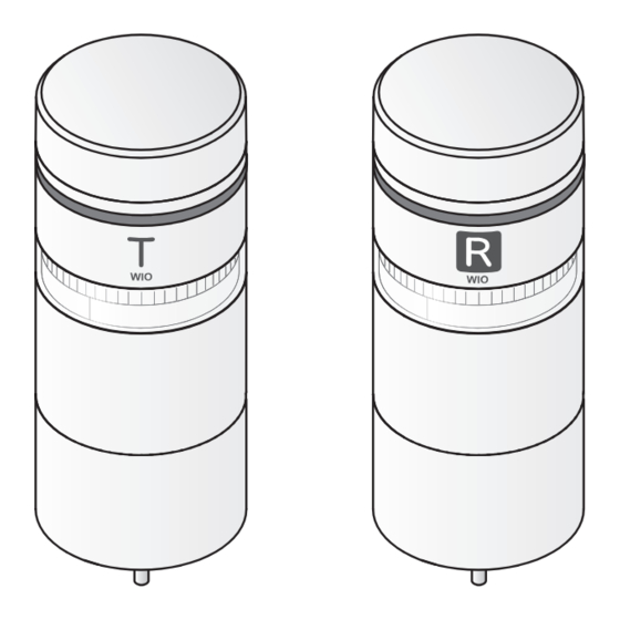
Page 9: Models
Wireless Control Unit 2. Models 2. Models 2.1. Transmitter Model Wireless Type Transmitter / Receiver Model Number Bluetooth Low Energy Transmitter * Bluetooth ver.5.0 LE Coded 2.2. Receiver Model Wireless Type Transmitter / Receiver LED Unit ↓ Model Number (empty) Bluetooth Low Energy Receiver LED Unit not included... -
Page 10: Transmitter
Wireless Control Unit 3. Package Contents 3. Contents 3.1. Transmitter WIO-B1T Accessories Transmitter: 1 Installation manual: 1 Hexagon Nut with Flange (M4) 3.2. Receiver WIO-B1R-RYG WIO-B1R Accessories Installation manual: 1 Receiver: 1 Hexagon Nut with Flange (M4) LED Unit: 1 each... -
Page 11: Andon Kit
Wireless Control Unit 3. Package Contents 3.3. Andon Kit WIO-B1S-001 WIO-B1T Accessories Transmitter: 1 Installation manual: 1 LED Unit: 1 each Hexagon Nut with Flange (M4) (Red) (Amber) (Green) WIO-B1R Accessories Installation manual: 1 Receiver: 1 Instruction Manual: 1... -
Page 12: Part Names And Dimensions ___________________________12
Wireless Control Unit 4. Part Names and Dimensions 4. Part Names and Dimensions 4.1. Transmitter ■ Main Unit ■ WIO Body Unit Function DIP Group ID DIP Head Cover Switch Switch Top Case Reset Button (Reboot Main Unit) WIO Body Unit Top view Indicator Guide mark... -
Page 13: Product Overview ________________________________13
Wireless Control Unit 5. Product Overview 5. Product Overview 5.1. Product Configuration • This product consists of a transmitter and a receiver. • Send signals from the transmitter to the receiver/repeater via Bluetooth Ⓡ to operate revolving lights, signal towers, sound and voice annunciator, and so on connected to the receiver/repeater. -
Page 14: Specifications
Wireless Control Unit 5. Product Overview 5.2. Specifications • The transmitter has 7 inputs and the receiver/repeater has 5 transistor outputs and 1 relay output. • You can attach additional units (LED units and buzzer unit) to this product. For information on how to install additional units, refer to "7.13. How to Attach and Detach Additional Units" ( ☞ page 73). CAUTION When LED and buzzer units are attached, operate with an input voltage from 21.6 to 26.4 VDC. -
Page 15: Operation
Wireless Control Unit 5. Product Overview 5.3. Operation This product works in conjunction with the following. Transmitter Receiver / Repeater Bluetooth wireless Answerback When the input information of the transmitter is successfully sent to the receiver, it lights up in light blue for 1 second. -
Page 16: For Proper Use Of This Product _________________________16
Wireless Control Unit 6. For Proper Use of This Product 6. For Proper Use of This Product 6.1. About the BLE Wireless Communication This product uses the short-range wireless communication standard Bluetooth Low Energy (2.4 GHz bandwidth wireless). Since this is the same 2.4 GHz band as a wireless LAN and other wireless devices, interference may occur when used within the same area, but since the communication methods are different, they can coexist. -
Page 17: Communication Distance
Wireless Control Unit 6. For Proper Use of This Product 6.3. Communication Distance The recommended maximum distance between products in the installation is 100 m. However, the spacing distance varies depending on obstructions between products or the type of obstruction. Some installation environments may result in significantly shorter spacing distances, so be sure to refer to "6.4. Radio Influence and Interference in Installation Environments"... -
Page 18: Radio Influence And Interference In Installation Environments
Wireless Control Unit 6. For Proper Use of This Product 6.4. Radio Influence and Interference in Installation Environments Check the following installation conditions, as they may significantly shorten the spacing distance. • When there is an obstacle (metal objects such as steel plates, wire mesh, or other noise-generating devices such as concrete walls or welding machines) between the products •... -
Page 19: Operation ___________________________________19
Wireless Control Unit 7. Operation 7. Operation 7.1. Procedure up to Operation • Please familiarize yourself with "6. For Proper Use of This Product" ( ☞ page 16) before operating this product. • This section describes the procedure required to start operating this product. Follow the steps below to prepare operating this product. -
Page 20: About The Dip Switches And Reset Button
Wireless Control Unit 7. Operation 7.2. About the DIP Switches and Reset Button This product has DIP switches and a reset button on the top of the WIO body unit. When setting up, turn the head cover counterclockwise to remove it, and then apply the settings. Head Cover Group ID DIP Switch Function DIP Switch... -
Page 21: Handling Dip Switches And Reset Button
Wireless Control Unit 7. Operation 7.2.2. Handling DIP Switches and Reset Button When setting the DIP switches and reset button, please set with following in mind. Failure to follow this instruction could result in product failure due to product damage, a deformed frame, or touching of the contacts. -
Page 22: Setting
Wireless Control Unit 7. Operation 7.3. Setting 7.3.1. Group ID Setting • Set when operating this product with multiple group IDs. • This product can operate up to 8 groups in the same area. • Turning on multiple products in the same area at the same time and attempting to pair them may result in unintended pairing between products. -
Page 23: How To Set The Group Id
Wireless Control Unit 7. Operation 7.3.1.1. How to Set the Group ID • Set up both transmitting and receiving products. • Read "7.2. About the DIP Switches and Reset Button" ( ☞ page 20) before handling the Group ID DIP Switch. ❶... -
Page 24: Function Settings
Wireless Control Unit 7. Operation 7.3.2. Function Settings This product has "Level Mode," "One-shot Mode", and "input logic switching" functions. Assign functions by turning this product’s Function DIP switch ON and OFF. For details on how to set functions, refer to "7.3.2.1. How to Set Functions". Point ●... -
Page 25: List Of Functions For The Function Dip Switch (Transmitter)
Wireless Control Unit 7. Operation 7.3.2.2. List of Functions for the Function DIP Switch (Transmitter) Switch Number Function Name Operation Description OFF: Disabled (factory default) Switch for unpairing. Unpairing ON: Execute unpairing Do not use when operating. Specify whether the input is detected at Level Mode / OFF: Level Mode (factory default) level (input ON or OFF) or at one-shot (rising... -
Page 26: Functions
Wireless Control Unit 7. Operation 7.4. Functions 7.4.1. Level Mode • The ON/OFF output of the receiver or repeater can be linked to the ON/OFF input of the transmitter. • Read "7.2. About the DIP Switches and Reset Button" ( ☞ page 20) before handling the DIP switches. Transmitter Function ON Input... -
Page 27: One-Shot Mode
Wireless Control Unit 7. Operation 7.4.2. One-shot Mode • This product can hold the output of the receiving product (hold output/output for 12 seconds) by pressing the ON input when the transmitting product is emitting the OFF input. • The output hold time can be set (hold output/output for 12 seconds) by the receiver's One-shot Mode output time setting. •... -
Page 28: One-Shot Output Clear
Wireless Control Unit 7. Operation 7.4.2.1. One-shot Output Clear • When operating in One-shot Mode, the output continuous state can be canceled by the receiving product. • To cancel the output continuous state, execute Clear Input (OFF→ON) to the receiver or repeater that is maintaining the output. -
Page 29: Input Logic A/B Switching Setting
Wireless Control Unit 7. Operation 7.4.3. Input Logic A/B Switching Setting • Select for this product the logical sum of the transmitter product's ON/OFF input and the receiver product's ON/OFF output [Input Logic A (NO Contact)], and the inverse logic of the transmitter product's ON/OFF input and the receiver product's ON/OFF output [Input Logic B (NC Contact)]. -
Page 30: Pairing
Wireless Control Unit 7. Operation 7.5. Pairing • For the pairing procedure of this product, pair the transmitting product with the receiving product in the order of the Pairing, 1 to 4, as shown in the figure below. • Pairing of this product refers to the state in which all devices (transmitter, receiver, and repeater) can connect to each other via Bluetooth. -
Page 31: How To Set Pairing
Wireless Control Unit 7. Operation CAUTION When pairing multiple products at the same time, use separate group IDs. Failure to follow the instruction may result in unintended pairing or failure to pair between products. If pairing between products is unintended, please unpair and pair again. (Refer to "7.6. - Page 32 Wireless Control Unit 7. Operation ● How to Pair the Receiving Product ❻ - Receiving product - Head Cover ❼ Confirm the receiving product is turned off. ❼ Remove the head cover from the WIO body unit. ❽ ❾ ❽ Group ID DIP Switch Set the Group ID DIP Switch.
-
Page 33: How To Unpairing
Wireless Control Unit 7. Operation 7.6. How to Unpairing • To delete the connection information (pairing information) registered for each product, such as adding/removing a repeater or replacing the product for maintenance, cancel the pairing and then pairing again. • Read "7.2. About the DIP Switches and Reset Button" ( ☞ page 20) before handling the DIP switches. •... -
Page 34: Using A Repeater
Wireless Control Unit 7. Operation 7.7. Using a Repeater • If the wireless quality is poor due to distance or obstacles between products, the wireless quality may be improved by installing a repeater. • This product can be used as a repeater by changing the receiver settings. •... -
Page 35: When Using Repeaters From Temporary Installation
Wireless Control Unit 7. Operation 7.7.2. When Using Repeaters from Temporary Installation • When using repeaters from when installation was performed, turn on the power from the transmitter, in turn, and pair as follows. • For products that are not paired, turn off the power. Transmitter Repeater Repeater... -
Page 36: How To Add A Repeater
Wireless Control Unit 7. Operation 7.7.3.1. How to Add a Repeater • When the indicator light is amber, a repeater can be added between products simply by turning on the repeater to be added (simple add function). • Read "7.2. About the DIP Switches and Reset Button" ( ☞ page 20) before handling the Repeater Setting Switch. •... -
Page 37: Checking The Indicator
Wireless Control Unit 7. Operation 7.8. Checking the Indicator Check the indicator status with its lighting. Transmitter Repeater Repeater Repeater Receiver Products Indicator Category Status Contents Light Status Transmitter Repeater Receiver Starting up Lemon light on Starting up After turning ON the power, in the start up state. ●... -
Page 38: Indicator Display Examples
Wireless Control Unit 7. Operation 7.8.1. Indicator Display Examples 7.8.1.1. From Power-on to Start of Operation ● Before pairing (factory default and after unpairing) ① When using a transmitter, receiver, and repeater (3 units) Repeater 2 Repeater 3 Transmitter Repeater 1 Receiver Pairing 1 Pairing 2... - Page 39 Wireless Control Unit 7. Operation ② When using a transmitter and receiver * Depending on the installation environment and radio wave conditions, the lighting and flashing status of the indicator may not transition as shown in the figure. Transmitter Receiver Pairing Explanatory notes Power on...
-
Page 40: Wireless Quality Under Operational Conditions
Wireless Control Unit 7. Operation 7.8.1.2. Wireless Quality under Operational Conditions ● When wireless quality is good Green light on Green light on Green light on Green light on Green light on Transmitter Repeater Repeater Repeater Receiver ● When wireless quality is poor Green light on Green light on Amber light on... -
Page 41: Answerback
Wireless Control Unit 7. Operation 7.9. Answerback A light blue indicator light for 1 second confirms that input information from the transmitter has successfully transmitted to the receiver and that the output device has been operated on. Normal operation Flashing green Flashing green Flashing green (for 2 seconds) -
Page 42: Mounting
Wireless Control Unit 7. Operation 7.10. Mounting 7.10.1 Direct Mounting The mounting method for the transmitter and receiver are the same. ❶ Head Cover In the mounting location, drill holes for mounting and wiring the product. WIO Body Unit ❷ The top case and bottom case Rotate the WIO body unit counterclockwise... -
Page 43: Mounting With Mounting Bracket (Option)
Wireless Control Unit 7. Operation 7.10.2. Mounting with Mounting Bracket (Option) ❶ Determine how to secure the mounting bracket. When securing with screws When securing with adhesive sheet As shown in the illustration below, drill mounting holes at the installation location. Peel away the yellow non-stick paper from the adhesive sheet and stick it to the location for the adhesive sheet. -
Page 44: Mounting With Pole (Option)
Wireless Control Unit 7. Operation 7.10.3. Mounting with Pole (Option) The following is an example installation using two circular brackets (SZP-003W: option) and Pole N. ❶ Head Cover Rotate the WIO body unit counterclockwise and detach from the direct mount bracket. WIO Body Unit •... - Page 45 Wireless Control Unit 7. Operation CAUTION Do not remove the waterproof gasket attached to the direct mount bracket. (Install together with the waterproof packing of the circular bracket) Installation using other than the supplied accessories is not warranted.
-
Page 46: Wiring
Wireless Control Unit 7. Operation 7.11. Wiring 7.11.1. Detaching the Terminal Block Connector To remove the terminal block, turn the terminal block connector screws (2 places) counterclockwise and pull out the terminal block connector. To install the terminal block, line up the guide marks on the WIO body unit and terminal block connector, and follow the removal procedure in reverse order to install. -
Page 47: Wiring The Terminal Block Connector
Wireless Control Unit 7. Operation 7.11.3. Wiring the Terminal Block Connector • Lead wires are not included with this product. Please provide your own. • Follow the steps below to wire the terminal block connector. WARNING Before any work is done, disconnect the power. Be sure wiring is carried out correctly. -
Page 48: Terminal Block Connector Pin Arrangement
Wireless Control Unit 7. Operation 7.11.4. Terminal Block Connector Pin Arrangement 7.11.4.1. Transmitter Item ① Power supply *1 Connected internally with No. ⑧ Guide mark ② Power supply (COM) *2 Connected internally with No. ⑨ and ⑫ ③ Input CH1 / LED Red ④... -
Page 49: Internal Circuit Diagram
Wireless Control Unit 7. Operation 7.11.5. Internal Circuit Diagram 7.11.5.1. Transmitter Photocoupler ③ Input: CH1/LED Red ④ Input:CH2/LED Amber ⑤ Input: CH3/LED Green ⑥ Input: CH4/LED Blue ⑦ Input: CH5/LED White ⑩ Input: CH6 ⑪ Input: Buzzer Fuse Fuse ①⑧ Power input Zener Diode ②⑨⑫... -
Page 50: Receiver
Wireless Control Unit 7. Operation 7.11.5.2. Receiver ● No-voltage contact output (NPN open collector) Photocoupler ③ Output: CH1 Zener Diode ④ Output: CH2 Fuse ⑤ Output: CH3 ⑥ Output: CH4 ⑦ Output: CH5 ⑩ COM CAUTION The output terminal is an NPN open collector output. For connection, use a product with the specification that it can be driven by an NPN transistor. - Page 51 Wireless Control Unit 7. Operation ● Relay output Relay ⑬ Output: CH6⊕ ⑭ Output: CH6⊖ CAUTION Relays have an open/close life. (Open/close life: 100,000 times or more *30 VDC, 3.0 A, resistive load open/close) Open/close life depends on the type of load, voltage, current, open/close quality, ambient atmosphere, and other factors. When connecting a load with a high inrush current, it is recommended to provide a protection circuit to reduce its effect.
-
Page 52: Handling The Ac Adapter
Do not use the product beyond the ratings in the product specifications. Do not use the AC adapter to operate any product other than the WIO series and PATLITE products for which the AC adapter is recommended. -
Page 53: How To Use The Ac Adapter
Wireless Control Unit 7. Operation 7.11.6.2. How to Use the AC Adapter ❶ ❸ Connect the extension cable lead wires to the power input terminal of this product. Fit A and B together. Push the AC plug in from above while pulling the C section. -
Page 54: Wiring Example
Wireless Control Unit 7. Operation 7.12. Wiring Example This section describes wiring examples for input and output devices. Wiring information can also be viewed from the QR code on the bottom of the WIO body unit. WIO Body WIO Body Unit Bottom Unit Direct Mount Bracket... -
Page 55: Wiring Example For Input Devices
Wireless Control Unit 7. Operation 7.12.1. Wiring Example for Input Devices 7.12.1.1. Typical Wiring Example Wiring example for each type of external contact. If you have any questions about a special application for this product, please contact our Technical Support Center listed on our website. - Page 56 Wireless Control Unit 7. Operation ● External contact classification: PLC (NPN transistor) Flashing/Buzzer External Contact Do not apply voltage to any wire other than the power. ⑭ Flashing COM Transmitter Input CH1 / LED Red ③ Input CH2 / LED Amber ④...
-
Page 57: Signal Tower
Wireless Control Unit 7. Operation 7.12.1.2. Signal Tower ● NE-M1ATB-M (touch sensor output) Connect 1:1 with the terminal you want to control Transmitter Input CH1 / LED Red ③ Touch Sensor Output (Lead Wire: Pink) Input CH2 / LED Amber ④... -
Page 58: Network Products
Wireless Control Unit 7. Operation 7.12.1.4. Network Products ● NBM-D88 Connect 1:1 with the terminal Transmitter Signal Output you want to control Terminal Block DO1 ⊕ Input CH1 / LED Red ③ DO1 ⊖ DO2 ⊕ Input CH2 / LED Amber ④... -
Page 59: Wiring Example For Output Devices
Wireless Control Unit 7. Operation 7.12.2. Wiring Example for Output Devices 7.12.2.1. Typical Wiring Example If you have any questions about a special application for this product, please contact our Technical Support Center listed on our website. Accidental wiring will result in product failure. Non-Voltage Contact Output Receiver / Repeater ③... -
Page 60: Sound And Audio Equipment
Wireless Control Unit 7. Operation 7.12.2.2. Sound and Audio Equipment ● BD-24A, BDV-15JF Connect 1:1 with the terminal you want to control Receiver / Repeater ③ Output: CH1 Output: CH2 ④ ⑤ Output: CH3 Output: CH4 ⑥ Output: CH5 ⑦ ⑩... - Page 61 Wireless Control Unit 7. Operation ● BKV-31JF Connect 1:1 with the terminal you want to control Receiver / Repeater ③ Output: CH1 Output: CH2 ④ ⑤ Output: CH3 Output: CH4 ⑥ ⑦ Output: CH5 STOP *Do not connect the BUSY terminal BUSY ⊕* to the receiver BUSY ⊖*...
- Page 62 Wireless Control Unit 7. Operation ● EHS-M1, EHV-M1 Connect 1:1 with the terminal you want to control Receiver / Repeater ③ Output: CH1 CH1 (Lead Wire: Cyan) Output: CH2 ④ CH2 (Lead Wire: Yellow) Output: CH3 ⑤ CH3 (Lead Wire: Pink) ⑥...
- Page 63 Wireless Control Unit 7. Operation ● RFV-24F Connect 1:1 with the terminal you want to control Receiver / Repeater ③ Output: CH1 Revolving Light (Lead Wire: Red) Output: CH2 ④ CH1 (Lead Wire: Cyan) Output: CH3 ⑤ CH2 (Lead Wire: Yellow) ⑥...
- Page 64 Wireless Control Unit 7. Operation ● RT-24VF Connect 1:1 with the terminal you want to control Receiver / Repeater ③ Output: CH1 Revolving Light (Lead Wire: Red) Output: CH2 ④ CH1 (Lead Wire: Cyan) ⑤ Output: CH3 CH2 (Lead Wire: Yellow) ⑥...
- Page 65 Wireless Control Unit 7. Operation ● LKEH-02F * The COM terminal of the receiver/repeater can be Receiver / Repeater ⑩ COM (Output for CH1-5) Common Line (Lead Wire: Yellow) connected to the flashing enable common line. Flashing Enable Common (Lead Wire: Brown)* Connect 1:1 with the terminal you want to control ③...
- Page 66 Wireless Control Unit 7. Operation ● LKEH-02FV *1 The COM terminal of the receiver/repeater can be Receiver / Repeater COM (Output for CH1-5) ⑩ Common Line (Lead Wire: Yellow) connected to the flashing enable common line. Flashing Enable Common (Lead Wire: Brown)*1 Connect 1:1 with the terminal you want to control ③...
-
Page 67: Led Display Board
Wireless Control Unit 7. Operation 7.12.2.3. LED Display Board ● VM96F Connect 1:1 with the terminal Signal Input Receiver / Repeater you want to control Terminal Block ③ Output: CH1 ⑭ Output: CH2 ④ ⑮ ⑤ Output: CH3 ⑯ ⑥ Output: CH4 ⑰... -
Page 68: Network Products
Wireless Control Unit 7. Operation 7.12.2.4. Network Products ● NBM-D88 Connect 1:1 with the terminal Signal Input Receiver / Repeater you want to control Terminal Block ③ Output: CH1 DI1 ⊕ DI1 ⊖ DI2 ⊕ Output: CH2 ④ DI2 ⊖ Output: CH3 ⑤... -
Page 69: Signal Light / Revolving Light
Wireless Control Unit 7. Operation 7.12.2.5. Signal Light / Revolving Light ● RLR-M1 Receiver / Repeater ③ Output: CH1 Output: CH2 ④ Output: CH3 ⑤ Do not connect to CH1 - 5 output or to COM terminals Output: CH4 ⑥ Output: CH5 ⑦... - Page 70 Wireless Control Unit 7. Operation ● SF-M1, SL-M1 Connect 1:1 with the terminal you want to control Receiver / Repeater ③ CH1 (Lead Wire: Green) Output: CH1 CH2 (Lead Wire: Blue) Output: CH2 ④ SF-M1, SL-M1 (DC model) ⑤ Output: CH3 Output: CH4 ⑥...
- Page 71 Wireless Control Unit 7. Operation ● NE-24A Connect 1:1 with the terminal you want to control Receiver / Repeater ③ Power Terminal*2 Output: CH1 Output: CH2 ④ ⑤ Output: CH3 Output: CH4 ⑥ Output: CH5 ⑦ NE-24A COM (Output for CH1 - 5)*1 ⑩...
-
Page 72: Signal Tower
Wireless Control Unit 7. Operation 7.12.2.6. Signal Tower ● LA6-D Connect 1:1 with the terminal Signal Input Terminal Block Receiver / Repeater you want to control ③ ① LED Tier 1 / Input 1 (Lead Wire: Red) Output: CH1 ② Output: CH2 ④... -
Page 73: How To Attach And Detach Additional Units
Wireless Control Unit 7. Operation 7.13. How to Attach and Detach Additional Units When attaching or detaching additional units (LED unit, Buzzer unit) to this product, be sure to follow the steps below. CAUTION The maximum number of attachments for each unit: 1 x this product + 5 x LED units + 1 x buzzer unit. Do not attach units beyond that. -
Page 74: Attaching The Led Unit And Buzzer Unit
Wireless Control Unit 7. Operation 7.13.1. Attaching the LED Unit and Buzzer Unit CAUTION Attach or detach units one at a time. Buzzer Unit Buzzer Unit Unit Unit Install one unit Install one unit at a time at a time Body Unit Body Unit Direct Mount... - Page 75 Wireless Control Unit 7. Operation CAUTION If additional unit does not attach properly to this product, confirm the tab of the cylinder-shaped part at the top of unit is fitted correctly into the groove. Additionally, depending on how it is detached, the tab may come out of the groove when detaching the additional unit from this product.
-
Page 76: System Configuration Example _________________________76
Wireless Control Unit 8. System Configuration Example 8. System Configuration Example 8.1. Status Notification The receiver can report the status of equipment with outputs. Cable Cable Transmitter Repeater / Receiver Equipment Alarm ● Configuration example Component Quantity Transmitter 1 unit Receiver 1 unit Repeater... -
Page 77: Collective Andon
Wireless Control Unit 8. System Configuration Example 8.2. Collective Andon The equipment operating status (signal lights) of each line can be centrally displayed as Andon. Cable Equipment Transmitter Repeater / Receiver Cable Equipment Transmitter Repeater / Receiver Cable Equipment Transmitter Repeater / Receiver ●... -
Page 78: Call The Person In Charge
Wireless Control Unit 8. System Configuration Example 8.3. Call the Person in Charge The system can be used to call the person in charge in the event of an abnormality. ● Call example 1 (For 12-second output in one-shot mode) Notify the office Cable Cable... - Page 79 Wireless Control Unit 8. System Configuration Example ● Call example 3 (For level mode) Notify the office Cable Cable Switch, etc. Transmitter Repeater / Receiver Revolving Light, etc. When you get to the site, turn the switch off. Stop instruction Cable Cable Transmitter...
-
Page 80: Troubleshooting _________________________________80
Wireless Control Unit 9. Troubleshooting 9. Troubleshooting Receiver / Transmitter Issue Checklist Repeater Check if the product is correctly installed and the wiring ● ● is correct. Indicator does not light up. Check if wiring for the power supply is correct. ●... -
Page 81: Replacement Parts _______________________________81
Wireless Control Unit 10. Replacement Parts 10. Replacement Parts O-ring 60 5 pieces... -
Page 82: Optional Parts _________________________________82
Wireless Control Unit 11. Optional Parts 11. Optional Parts 11.1. Supported Units ● LED unit: LR6-E- □ , LR6-E- □ Z, LR6-E-MZ 1 each ● Buzzer unit: LR6-BW... -
Page 83: Supported Options
Wireless Control Unit 11. Optional Parts 11.2. Supported Options ● Wall Mounting Bracket: SZK-003W, SZK-001U* ● Pole: POLE22- □ 00AT, POLE22- □ 00AN (Available only when SZP-003W is mounted) ● Circular bracket: SZP-001W* , SZP-002U* , SZP-003W* , SZW-001W ● Tilt Bracket: SZQ-001W* ●... -
Page 84: Specifications _________________________________84
Wireless Control Unit 12. Specifications 12. Specifications 12.1. Transmitter Rated Voltage 12 to 24 VDC (24 VDC when LED unit or buzzer unit is installed) Operating Voltage Range 10.8 to 26.4 VDC (21.6 to 26.4 VDC when LED unit or buzzer unit is installed) Main Unit Maximum: 63 mA or less 24V DC input... - Page 85 Wireless Control Unit 12. Specifications Lever Group ID DIP Switch, Function DIP Switch, Reset Button Accessories Hexagon nut with flange (M4) x 3...
-
Page 86: Receiver
Wireless Control Unit 12. Specifications 12.2. Receiver Rated Voltage 12 to 24 VDC (24 VDC when LED unit or buzzer unit is installed) Operating Voltage Range 10.8 to 26.4 VDC (21.6 to 26.4 VDC when LED unit or buzzer unit is installed) Main Unit Maximum: 52 mA or less 24V DC input... - Page 87 Wireless Control Unit 12. Specifications Group ID DIP Switch, Function DIP Switch, Reset Button Lever Repeater Setting Switch Accessories Hexagon nut with flange (M4) x 3 *1 Our products with a recommended contact capacity of "35V DC or more" can be used only when operated within the allowable voltage range of this product (10.8 to 26.4 VDC).
Need help?
Do you have a question about the WIO-B1T and is the answer not in the manual?
Questions and answers