
Related Manuals for Omron NXR Series


Summary of Contents for Omron NXR Series
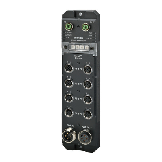
- Page 1 Environment-resistive Remote Terminal NXR-series IO-Link Master Unit for EtherCAT ® User’s Manual NXR-ILM08C-ECT IO-Link Master Unit for EtherCAT W640-E1-01...
- Page 2 Moreover, because OMRON is constantly striving to improve its high-quality products, the information contained in this manual is subject to change without notice. • Every precaution has been taken in the preparation of this manual. Nevertheless, OMRON assumes no responsi- bility for errors or omissions.
-
Page 3: Intended Audience
Introduction Introduction Thank you for purchasing an NXR-series IO-Link Master Unit for EtherCAT. This manual contains information that is necessary to use the NXR-series IO-Link Master Unit for EtherCAT. Please read this manual and make sure you understand the functionality and performance of the NXR-series IO-Link Master Unit for EtherCAT before you attempt to build an IO-Link System. -
Page 4: Manual Structure
Manual Structure Manual Structure Page Structure The following page structure is used in this manual. Level 1 heading 4 Installation and Wiring Level 2 heading Mounting Units Level 3 heading Level 2 heading Gives the current Level 3 heading headings. 4-3-1 Connecting Controller Components The Units that make up an NJ-series Controller can be connected simply by pressing the Units together... -
Page 5: Special Information
Manual Structure Special Information Special information in this manual is classified as follows: Precautions for Safe Use Precautions on what to do and what not to do to ensure safe usage of the product. Precautions for Correct Use Precautions on what to do and what not to do to ensure proper operation and performance. Additional Information Additional information to read as required. - Page 6 Manual Structure NXR-series IO-Link Master Unit for EtherCAT User’s Manual (W640)
-
Page 7: Sections In This Manual
Sections in this Manual Sections in this Manual Features and System Setting Up IO-Link Configuration Devices Specifications and Troubleshooting Application Procedures Inspection and Part Names and Maintenance Functions Designing the Power Appendices Supply System Installation and Wiring Index EtherCAT and IO-Link Communications Setting Up IO-Link Master Unit... -
Page 8: Table Of Contents
CONTENTS CONTENTS Introduction ......................1 Intended Audience............................1 Applicable Products ............................1 Manual Structure...................... 2 Page Structure..............................2 Special Information ............................3 Precaution on Terminology ..........................3 Sections in this Manual ................... 5 Terms and Conditions Agreement................ 12 Warranty, Limitations of Liability ........................12 Application Considerations ..........................13 Disclaimers ..............................13 Statement of security responsibilities for assumed use cases and against threats........14 Safety Precautions.................... - Page 9 CONTENTS 1-3-1 Features as an EtherCAT Slave....................1-8 1-3-2 Features as an IO-Link Master....................1-8 System Configuration......................1-11 Support Software .........................1-13 Functions of the IO-Link Master Unit .................1-14 Section 2 Specifications and Application Procedures Specifications.........................2-2 2-1-1 General Specifications ........................2-2 2-1-2 EtherCAT Communications Specifications..................2-2 2-1-3 Unit Specifications........................2-3 Application Procedures......................2-6...
- Page 10 CONTENTS Connecting the Power Supplies ..................5-10 5-3-1 Installation Precautions ......................5-10 5-3-2 Preparing for Wiring ........................5-10 5-3-3 Connecting Power Supply Cables to External Power Supplies ..........5-11 5-3-4 Connecting Power Supply Cables.....................5-12 Connecting I/O Cables......................5-18 5-4-1 Installation Precautions ......................5-18 5-4-2 Preparing for Wiring ........................5-18 5-4-3 Connecting I/O Cables ......................5-18 5-4-4...
- Page 11 CONTENTS Section 9 Functions List of Functions ........................9-3 Sysmac Device Functionality ....................9-5 9-2-1 Error Notifications Based on the Sysmac Error Status ...............9-5 9-2-2 Saving Node Address Settings ....................9-5 9-2-3 Verifying the EtherCAT Network Configuration Using Serial Numbers ........9-6 9-2-4 SII Data Checking ........................9-6 Communications Mode Settings ..................9-7 9-3-1 Overview of Function ........................9-7...
- Page 12 CONTENTS Section 10 Setting Up IO-Link Devices 10-1 Methods for Setting IO-Link Devices .................10-2 10-2 Setting IO-Link Devices with the CX-ConfiguratorFDT ............10-3 10-2-1 Overview of the CX-ConfiguratorFDT ..................10-3 10-2-2 Flow of Operations for the CX-ConfiguratorFDT ...............10-4 10-2-3 Installing the CX-ConfiguratorFDT in Your Computer ...............10-5 10-2-4 Installing IODD Files for IO-Link Devices from Other Companies in the CX-ConfiguratorFDT.10-5 10-2-5...
- Page 13 CONTENTS 12-2-3 Replacing IO-Link Devices ......................12-5 12-2-4 Replacing the IO-Link Master Unit and IO-Link Devices at the Same Time......12-5 Appendices CoE Objects........................... A-2 A-1-1 Object Dictionary Area ....................... A-2 A-1-2 Data Types ..........................A-2 A-1-3 Format of Objects........................A-3 A-1-4 Communication Objects ......................
-
Page 14: Terms And Conditions Agreement
Omron’s exclusive warranty is that the Products will be free from defects in materials and work- manship for a period of twelve months from the date of sale by Omron (or such other period ex- pressed in writing by Omron). Omron disclaims all other warranties, express or implied. -
Page 15: Application Considerations
WAY CONNECTED WITH THE PRODUCTS, WHETHER SUCH CLAIM IS BASED IN CONTRACT, WARRANTY, NEGLIGENCE OR STRICT LIABILITY. Further, in no event shall liability of Omron Companies exceed the individual price of the Product on which liability is asserted. Application Considerations... -
Page 16: Statement Of Security Responsibilities For Assumed Use Cases And Against Threats
Product. Errors and Omissions Information presented by Omron Companies has been checked and is believed to be accurate; how- ever, no responsibility is assumed for clerical, typographical or proofreading errors or omissions. Statement of security responsibilities for assumed use cases and... -
Page 17: Safety Precautions
Safety Precautions Safety Precautions Definition of Precautionary Information The following notation is used in this manual to provide precautions required to ensure safe usage of the NXR-series IO-Link Master Unit for EtherCAT. The safety precautions that are provided are extremely important to safety. Always read and heed the information provided in all safety precautions. -
Page 18: Warnings
Safety Precautions Warnings WARNING During Power Supply Do not touch the terminal section while power is ON. Electric shock may occur. Do not attempt to take any Unit apart. In particular, high-voltage parts are present in Units that supply power while power is supplied or immediately after power is turned OFF. - Page 19 Safety Precautions Power Supply Design Follow the instructions in this manual to correctly perform power supply design and wir- ing. Inputting voltages or currents that are outside of the specified ranges, as well as in- correct wiring, may cause failure or fire. Wiring Make sure that the grounds (0 V) of the Unit/input power supply and the output power supply are at the same potential.
- Page 20 Safety Precautions Data recovery Backup data and keep the data up-to-date periodically to prepare for data loss. When using an intranet environment through a global address, connecting to a SCADA or an unauthorized terminal such as an HMI or to an unauthorized server may result in network security issues such as spoofing and tampering.
-
Page 21: Cautions
Safety Precautions Cautions Caution Online Editing Execute online editing only after confirming that no adverse effects will be caused by de- viations in the timing of I/O. If you perform online editing, the task execution time may exceed the task period, I/O may not be refreshed with external devices, input signals may not be read, and output timing may change. -
Page 22: Precautions For Safe Use
Precautions for Safe Use Precautions for Safe Use Transporting • When transporting any Unit, use the special packing box for it. Also, do not subject the Unit to excessive vibration or shock during transportation. • Do not drop any Unit or subject it to abnormal vibration or shock. Doing so may result in Unit failure or malfunction. - Page 23 Precautions for Safe Use • The maximum power supply current is 9 A, which is the sum of the Unit/input power supply current and the output power supply current. Do not use the Unit beyond the maximum power supply current. Otherwise, an excess current flows through the power supply cable, and it may cause fire. •...
- Page 24 Precautions for Safe Use • EtherCAT communications are not always established immediately after the power supply is turned ON. Use the system-defined variables in the user program to confirm that communications are established before attempting control operations. • If frames sent to EtherCAT slaves are lost due to noise or other causes, slave I/O data is not com- municated, and the intended operation is sometimes not achieved.
- Page 25 Precautions for Safe Use d) Forced refreshing • After you change the Unit settings including IO-Link settings, always sufficiently check the safety at the connected devices before you transfer them. Maintenance • Do not use paint thinner when cleaning. Use commercially available alcohol. •...
-
Page 26: Precautions For Correct Use
Precautions for Correct Use Precautions for Correct Use Storage, Mounting, and Wiring • Do not operate or store the Units in the following locations. Doing so may result in malfunction or in operation stopping. Locations subject to direct sunlight Locations subject to temperatures or humidity outside the range specified in the specifications Locations subject to condensation as the result of severe changes in temperature Locations subject to corrosive or flammable gases Locations subject to dust (especially iron dust) or salts... -
Page 27: Regulations And Standards
Concepts Conformance to EMC Regulations OMRON devices that comply with EU Directives also conform to the related EMC regulations so that they can be more easily built into other devices or the overall machine. The actual products have been checked for conformity to EMC standards.*1 Whether the products conform to the standards in the system used by the customer, however, must be checked by the customer. -
Page 28: Conformance To Ul And Csa Standards
Regulations and Standards Conformance to UL and CSA Standards Some NXR-series products comply with UL and CSA standards. If you use a product that complies with UL or CSA standards and must apply those standards to your machinery or devices, refer to the Instruction Sheet that is provided with the product. The Instruction Sheet provides the application conditions for complying with the standards. -
Page 29: Unit Versions
Unit Versions Unit Versions Unit Versions A “unit version” has been introduced to manage the Units in the NXR Series according to differences in functionality accompanying Unit upgrades. Notation of Unit Versions on Products The unit version is given with the Unit specifications on the side of the Unit. -
Page 30: Related Manuals
NJ301-££££ NJ101-££££ IO-Link Sensor 9541795-1 E3Z-£8£-IL£ Learning the ven- The following information is provid- Index List dor IDs, device ed on OMRON IO-Link sensors, 9540292-0 E2E(Q)-£-IL£ IDs, I/O data which are IO-Link devices. 9539397-1 E3S-DCP21-IL£ • (process data), IO-Link physical layer and objects (serv- •... -
Page 31: Terminology
Terminology Terminology Abbre- Term Description viation application layer status, AL status Status for indicating information on errors that occur in an application on a slave. CAN application protocol over Ether- A CAN application protocol service implemented on EtherCAT. CAN in Automation CiA is the international users’... - Page 32 Terminology Abbre- Term Description viation An acronym for standard input/output. A general term for the communi- cations modes to input and output digital signals (ON/OFF signals). SIO (DI) Mode One of the communications mode settings. A communications mode to input digital signals (ON/OFF signals) from input devices. SIO (DO) Mode One of the communications mode settings.
- Page 33 Terminology Abbre- Term Description viation process data I/O data in the IO-Link devices. You can allocate a maximum of 32 bytes of process data in the IO-Link master. A generic term for the IO-Link process input data and IO-Link process output data in IO-Link devices.
-
Page 34: Revision History
Revision History Revision History A manual revision code appears as a suffix to the catalog number on the front and back covers of the manual. Cat. No. W640-E1-01 Revision code Revision Date Revised content code December 2023 Original production NXR-series IO-Link Master Unit for EtherCAT User’s Manual (W640) -
Page 35: Features And System Configuration
Features and System Configura- tion This section describes the features and system configuration of the NXR-series IO- Link Master Unit for EtherCAT. Introduction to the IO-Link Master Unit............1-2 1-1-1 Introduction to IO-Link ..................1-3 1-1-2 Functions of Port Pins and Connected External Devices........ 1-3 Introduction to EtherCAT................ -
Page 36: Introduction To The Io-Link Master Unit
1 Features and System Configuration Introduction to the IO-Link Master Unit The NXR-series IO-Link Master Unit for EtherCAT is an EtherCAT slave that provides IO-Link master functions with an environmental resistance of IP67. An NXR-series IO-Link Master Unit for EtherCAT receives data from the EtherCAT master through the EtherCAT network and outputs the data to connected external devices. -
Page 37: Introduction To Io-Link
1 Features and System Configuration 1-1-1 Introduction to IO-Link IO-Link is a standard interface for 1:1 (point-to-point) connections with sensors, actuators, or other de- vices as defined in international standard IEC 61131-9. Devices that previously could not exchange digital I/O signals can now exchange information such as detected amounts. - Page 38 1 Features and System Configuration Communica- tions mode of Pin name Function of port pin port pin IO-Link Mode Pin 4 IO-Link communications function. Communicates with an IO-Link device. Pin 2 Pin 2 cannot be set to IO-Link Mode. SIO (DI) Mode Pin 4 Digital input function.
-
Page 39: Introduction To Ethercat
1 Features and System Configuration Introduction to EtherCAT EtherCAT (Ethernet Control Automation Technology) is a high-performance industrial network system that enables faster and more efficient communications based on Ethernet. Each node achieves a short communications cycle time by transmitting Ethernet frames at high speed. Although EtherCAT is a unique communications protocol, standard Ethernet technology is used for the physical layer, which means you can use Ethernet cables for wider application. -
Page 40: Types Of Ethercat Communications
1 Features and System Configuration Ethernet frame Ethernet Ethernet data (1,498 bytes max.) header 1st to nth EtherCAT datagrams EtherCAT frame EtherCAT header ..1st EtherCAT 2nd EtherCAT nth EtherCAT datagram datagram datagram Header Data WKC: Working counter 1-2-2 Types of EtherCAT Communications The following two types of communications are available with EtherCAT. - Page 41 1 Features and System Configuration Slave EtherCAT master Slave Slave Slave Ethernet frame Ether Ethernet 1st EtherCAT 2nd EtherCAT 3rd EtherCAT x x x header datagram datagram datagram header Logical process data Data a Data b Data c Mailbox Communications (SDO Communications) SDO communications is used to perform message communications.
-
Page 42: Features Of The Io-Link Master Unit
1 Features and System Configuration Features of the IO-Link Master Unit This section describes the following features of the NXR-series IO-Link Master Unit for EtherCAT. • Features as an EtherCAT slave • Features as an IO-Link master 1-3-1 Features as an EtherCAT Slave The features of the NXR-series IO-Link Master Unit for EtherCAT as an EtherCAT slave are described below. - Page 43 1 Features and System Configuration Because the IO-Link Master Unit can cyclically read analog data such as the amount of incident light, it can be used for predictive maintenance based on detection of such things as decreases in the amount of light. *1.
- Page 44 1 Features and System Configuration (Refer to 9-10 Monitoring Unit/Input Power Supply Voltage on page 9-24 and 9-11 Monitoring Out- put Power Supply Voltage on page 9-26.) Easy Replacement of IO-Link Devices The IO-Link Master Unit supports the backup/restore function specified by the IO-Link standard. Therefore, you can back up the parameter settings of IO-Link devices to the IO-Link Master Unit.
-
Page 45: System Configuration
1 Features and System Configuration System Configuration An example of a system configuration for an NXR-series IO-Link Master Unit for EtherCAT is shown below. The example uses an NJ/NX-series CPU Unit and an NY-series Industrial PC. (A) EtherCAT master: (H) Support Connected to peripheral Software NJ/NX-series CPU Unit or NY-series Industrial PC... - Page 46 IO-Link master. NXR-series The NXR-series IO-Link I/O Hub is an OMRON IO-Link device. It exchanges data with IO-Link I/O the NXR-series IO-Link Master Unit for EtherCAT in IO-Link communications. You can connect non-IO-Link connected external devices to the NXR-series IO-Link I/O Hub.
-
Page 47: Support Software
1 Features and System Configuration Support Software The following table shows the Support Software that you can use to configure a system of the NXR- series IO-Link Master Unit for EtherCAT. The Support Software used depends on the scope of the ap- plicable system. -
Page 48: Functions Of The Io-Link Master Unit
1 Features and System Configuration Functions of the IO-Link Master Unit Refer to the following section for details on the functions of the NXR-series IO-Link Master Unit for EtherCAT. • Section 9 Functions on page 9-1 1-14 NXR-series IO-Link Master Unit for EtherCAT User’s Manual (W640) - Page 49 Specifications and Application Procedures This section describes the specifications and application procedures for the IO-Link Master Unit. Specifications ....................2-2 2-1-1 General Specifications ..................2-2 2-1-2 EtherCAT Communications Specifications ............2-2 2-1-3 Unit Specifications................... 2-3 Application Procedures ................. 2-6 NXR-series IO-Link Master Unit for EtherCAT User’s Manual (W640)
-
Page 50: Specifications
Listed (UL61010-2-201) EU: EN 61131-2, RCM KC: KC Registration UKCA IO-Link conformance EtherCAT conformance Note Refer to the OMRON website (www.ia.omron.com) or ask your OMRON representative for the most recent applicable standards. 2-1-2 EtherCAT Communications Specifications Item Specification Communications protocols... -
Page 51: Unit Specifications
2 Specifications and Application Procedures Item Specification Topology *1*2 Depends on the specifications of the EtherCAT master Transmission media Category 5 or higher twisted-pair cable (Recommended cable: double- shielded cable with aluminum tape and braiding) Transmission distance Distance between nodes (slaves): 50 m or less Noise immunity Conforms to IEC 61000-4-4, 1 kV or more Node address setting method... - Page 52 2 Specifications and Application Procedures Item Specification Number of connected Units when No restrictions if power supply specifications are met. supplying power with through-wir- Mounting method Mounting with M5 screws Mounting strength 100 N Installation orientation and restric- Installation orientation: 6 possible orientations tions Restrictions: No restrictions •...
- Page 53 2 Specifications and Application Procedures Item Specification Digital out- Power supply used Output power supply puts for pin Internal I/O com- 4 or digital outputs for Output type Open-drain pin 2 (in SIO Rated voltage 24 VDC (20.4 to 26.4 VDC) (DO) Mode) Maximum load cur- 2 A/pin...
-
Page 54: Application Procedures
2 Specifications and Application Procedures Application Procedures This section describes the basic application procedures for the IO-Link Master Unit. Step Item Description Reference Preparing for Confirming Suit- Confirm that the following restrictions for the IO- Section 4 Designing the Work ability of Speci- Link Master Unit are met. - Page 55 2 Specifications and Application Procedures Step Item Description Reference Going Online from the Sysmac Stu- Set up communications with the Controller in the Sysmac Studio Version 1 dio and Downloading the Configura- Sysmac Studio and go online with the Controller. Operation Manual (Cat.
- Page 56 2 Specifications and Application Procedures NXR-series IO-Link Master Unit for EtherCAT User’s Manual (W640)
- Page 57 Part Names and Functions This section describes the names and functions of the parts of the IO-Link Master Unit. Parts and Names .................... 3-2 Indicators ......................3-4 3-2-1 Status Indicators....................3-4 3-2-2 I/O Indicators ....................3-6 Rotary Switches ..................... 3-9 3-3-1 ID Switch ......................
-
Page 58: Parts And Names
3 Part Names and Functions Parts and Names This section gives the names of the parts of the IO-Link Master Unit. Letter Name Function EtherCAT communica- The connector for EtherCAT port (input). • tions connector (input) M12 connector (D-coding, female) Connect a communications cable. - Page 59 3 Part Names and Functions Letter Name Function Cover mounting holes The screw holes for mounting the rotary switch cover. They are provided in two loca- tions. The above figure shows the holes when the cover is mounted with screws. Rotary switches The switches for setting the Explicit Device ID and for the I/O port quick settings.
-
Page 60: Indicators
3 Part Names and Functions Indicators The IO-Link Master Unit has the following indicators. These indicators are described below. • Status indicators • I/O indicators 3-2-1 Status Indicators RUN Indicator This indicator shows the operating status of the Unit. Color Status Description Green... - Page 61 3 Part Names and Functions Color Status Description PDI Watchdog Timeout Double flash Process Data WDT Error • Blinking Slave Unit Verification Error • Mailbox Setting Error • RxPDO Setting Error • TxPDO Setting Error • PDO WDT Setting Error •...
-
Page 62: I/O Indicators
3 Part Names and Functions U/IN PWR Indicator This indicator shows the status of the Unit/input power supply. Color Status Description Green The Unit/input power is supplied. Not lit The Unit/input power is not supplied. OUT PWR Indicator This indicator shows the status of the output power supply. Color Status Description... - Page 63 3 Part Names and Functions Contact number Port number Example: I/O indicator for port 1 Letter Name Description Pin 4/Pin 1 status This indicator shows the status of pin 4/pin 1 for each port. indicator For each port, the contact numbers for digital input or digital output are given. De- tails are given below.
- Page 64 3 Part Names and Functions Pin 2 Status Indicator This indicator shows the digital I/O status or short-circuit status for pin 2. Description Color Status SIO (DI) Mode SIO (DO) Mode Disabled Yellow The input is ON The output is ON •...
-
Page 65: Rotary Switches
3 Part Names and Functions Rotary Switches Use the rotary switches for setting the Explicit Device ID and the I/O port quick settings of the IO-Link Master Unit. These rotary switches are described below. 3-3-1 ID Switch The ID switch sets the Explicit Device ID which is used to enable the EtherCAT master to recognize the IO-Link Master Unit on the EtherCAT network. -
Page 66: Set Switch
3 Part Names and Functions The setting range of the ID depends on the specifications of the connected EtherCAT master. Check the specifications of the EtherCAT master for the supported ID setting range of the EtherCAT master. Precautions for Correct Use •... -
Page 67: Connectors
3 Part Names and Functions Connectors The IO-Link Master Unit has the following connectors. These connectors are described below. • EtherCAT communications connectors • Power supply connectors • I/O connectors 3-4-1 EtherCAT Communications Connectors The EtherCAT communications connectors are used for EtherCAT communications. In this manual, they are sometimes referred to as "communications connectors". -
Page 68: I/O Connectors
3 Part Names and Functions Power Supply Connector (Input) The connector for supplying the following power. Connect the power supply cable to an external power supply. • Unit/input power supply • Output power supply Power Supply Connector (Output) The connector for supplying Unit/input power and output power from the local node to another node of the IO-Link Master Unit. - Page 69 3 Part Names and Functions The specifications are as follows: • Connector structure M12 connector (A-coding, female) × 8 • Pin arrangement Signal Pin name Description name Pin 1 Device power supply + Pin 2 One of the following functions is set depending on the communications mode setting.
- Page 70 3 Part Names and Functions 3-14 NXR-series IO-Link Master Unit for EtherCAT User’s Manual (W640)
-
Page 71: Designing The Power Supply System
Designing the Power Supply Sys- This section describes how to design the power supply system for the IO-Link Master Unit. Power Supply Types and Power Supply System ........4-2 4-1-1 Power Supply Types and Applications ............4-2 4-1-2 Power Supply System ..................4-2 Designing the Power Supply System ............ -
Page 72: Power Supply Types And Power Supply System
4 Designing the Power Supply System Power Supply Types and Power Sup- ply System This section describes the power supply types and applications and the power supply system for the IO-Link Master Unit. 4-1-1 Power Supply Types and Applications This section describes the power supply types and applications for the IO-Link Master Unit. Power Supply Types There are the following two types of power supplies that supply power to the IO-Link Master Unit. - Page 73 4 Designing the Power Supply System Method Description Feature Direct Connect the external power supplies to the power supply connector (input) of each This method power IO-Link Master Unit. does not supply The power supply connector (output) is not used. cause voltage drop in through-wiring...
- Page 74 4 Designing the Power Supply System IO-Link Master Unit IO-Link Master Unit IO-Link Master Unit I/O connectors Internal Internal Internal (P1 to P8) circuits circuits circuits Power supply To external connector (input) devices (PWR IN) Power supply cable Power supply connector (output) (PWR OUT) Unit/input power supply...
- Page 75 4 Designing the Power Supply System Power Supply System with Through-wiring An example is shown below. Connect the external power supplies to the power supply connector (input) of one IO-Link Master Unit. Then, connect the power supply connector (output) of the Unit to the power supply connector (input) of another IO-Link Master Unit with a power supply cable.
- Page 76 4 Designing the Power Supply System Precautions for Correct Use • Always use separate power supplies for the Unit/input power supply and the output power supply. If you supply power from the same power supply, load variations in output devices may cause malfunctions.
-
Page 77: Designing The Power Supply System
4 Designing the Power Supply System Designing the Power Supply System This section describes how to design the power supply system for the IO-Link Master Unit. WARNING Follow the instructions in this manual to correctly perform power supply design and wiring. - Page 78 4 Designing the Power Supply System Reference for confirmation meth- Design condition (a) The sum of the total current consumption from the Unit/input power Calculating the Total Current Con- supply and output power supply must not exceed the maximum power sumption in Direct Power Supply on page 4-8 supply current of the IO-Link Master Unit.
- Page 79 4 Designing the Power Supply System Total Current Consumption from Output Power Supply = (Current consumption from output power supply) + (Current consumed between IO-Link Master Unit and IO-Link devices) + (Current consumed between IO-Link Master Unit and non-IO-Link output devices) The items of the formula are described below.
- Page 80 4 Designing the Power Supply System Conditions for IO-Link Master Unit Conditions for connected external device Port setting Unit Product name Specification Communications name Port name Pin name mode ILM1 Port 1 Pin 4 IO-Link Mode IO-Link device Current consumption: (with digital outputs 50 mA Pin 2...
- Page 81 4 Designing the Power Supply System Unit Power supply Item to calculate for total cur- Calculation result name type rent consumption Output power Current consumption from out- 100 mA according to the specifications of the supply put power supply IO-Link Master Unit Current consumed between IO- Port 2 is calculated.
- Page 82 4 Designing the Power Supply System The formula is the same as that of ILM2. (Total current consumption of ILM3 from Unit/input power supply) + (Total current consumption of ILM3 from output power supply) ≈ 2.23 A This example is acceptable because the sum of the total current consumption for each Unit is be- low 9 A, the maximum power supply current of the IO-Link Master Unit.
-
Page 83: Design Method For Power Supply System With Through-Wiring
4 Designing the Power Supply System Unit name Voltage drop ILM1 0.40 V (4 A is used because the cable length is 1 m and the total current consumption is 3.30 ILM2 0.51 V (3 A is used because the cable length is 3 m and the total current consumption is 2.23 ILM3 0.69 V (3 A is used because the cable length is 5 m and the total current consumption is 2.23 From the above results, the voltage of each input power supply to each Unit is calculated as fol-... - Page 84 4 Designing the Power Supply System Design condition Reference for confirmation method (b) The input circuit specifications of IO-Link Master Unit and the volt- Calculating the Voltage Drop in Power age specifications of connected external devices are met even if the Supply with Through-wiring on page 4-17 Unit/input power supply voltage drops.
- Page 85 4 Designing the Power Supply System If the calculated value does not meet the specified condition, add external power supplies so that the condition is met. Example: A system with additional external power supplies ILM1 ILM2 ILM3 Unit/input power supply Unit/input power supply Output power supply Output power supply...
- Page 86 4 Designing the Power Supply System Configuration Example ILM1 ILM2 ILM3 Iui1 Iui2 Iui3 Iui2 + Iui3 Io2 + Io3 Iui1 + Iui2 + Iui3 Unit/input power supply Io1 + Io2 + Io3 Output power supply Iui1: Total current consumption of ILM1 from Unit/input power supply Iui2: Total current consumption of ILM2 from Unit/input power supply Iui3: Total current consumption of ILM3 from Unit/input power supply Io1: Total current consumption of ILM1 from output power supply...
- Page 87 4 Designing the Power Supply System = (Iui3) + (Io3) ≈ 2.23 A The sum of the current consumption of each Unit supplied from external power supplies is calculat- ed as follows. (Iui1 + Iui2 + Iui3 + Io1 + Io2 + Io3) = (3.30 A + 2.23 A + 2.23 A) = 7.76 A This example is acceptable because the calculation result is below 9 A, the maximum power supply...
- Page 88 4 Designing the Power Supply System Item Conditions Power supply The cable length is as follows. cable length ILM1 ILM2 ILM3 Power supply cable 1: 1 m Power supply cable 3: 1 m Power supply cable 2: 1 m Unit/input power supply Output power supply •...
- Page 89 4 Designing the Power Supply System From the above results, the voltage of each input power supply to each Unit is calculated as fol- lows. a. Voltage of each input power supply to ILM1 Voltage of each power supply = 24.0 V - Voltage drop in power supply cable 1 = 24.0 V - 0.80 V = 23.20 V b.
-
Page 90: Design Method For Power Supply System With Through-Wiring
• Has double or reinforced insulation between the input and output. • Has an output voltage of 24 VDC (20.4 to 26.4 VDC). Recommended power supplies: S8VK-S Series (manufactured by OMRON) Power Supply Capacity Calculate the total current consumptions from the Unit/input power supply and output power supply of the IO-Link Master Unit and the power supply capacity of each power supply according to the calcula- tion methods described in the following sections. - Page 91 4 Designing the Power Supply System Overcurrent is the current that flows when an excessive load is connected and one of the following ratings is exceeded. • For the Unit/input power supply and output power supply (common), maximum power supply current and maximum port current •...
- Page 92 4 Designing the Power Supply System Unit/input power supply Protective device Protective device Output power supply Unit/input power supply Protective device Protective device Protective device Protective device Output power supply 4-22 NXR-series IO-Link Master Unit for EtherCAT User’s Manual (W640)
-
Page 93: Installation And Wiring
Installation and Wiring This section describes how to install and wire the IO-Link Master Unit. Installing Units....................5-2 5-1-1 Installation Precautions ................... 5-2 5-1-2 Installation Orientations................... 5-2 5-1-3 Installation Method ..................5-2 EtherCAT Network Wiring................5-4 5-2-1 Installation Standards..................5-4 5-2-2 Installation Precautions ................... -
Page 94: Installing Units
5 Installation and Wiring Installing Units This section describes how to install the IO-Link Master Unit. 5-1-1 Installation Precautions To increase the reliability of the IO-Link Master Unit and take complete advantage of its functionality, observe the following precautions. Do not install the IO-Link Master Unit in the following locations. •... - Page 95 5 Installation and Wiring • Installing the Unit Installing the Rotary Switch Cover Use the two cover mounting holes to install the rotary switch cover. Cover mounting holes Tighten the M3 screws to the following torque. You can maintain the IP67 protective structure when the screws are tightened to the specified tightening torque.
-
Page 96: Ethercat Network Wiring
5 Installation and Wiring EtherCAT Network Wiring This section describes how to install the EtherCAT network for the IO-Link Master Unit. Refer to the user’s manual for EtherCAT master that you use for how to wire an EtherCAT master. 5-2-1 Installation Standards To ensure that the EtherCAT communication network is installed properly, refer to IEC 61784-5-12 standard in conjunction with IEC 61918. -
Page 97: Preparing For Wiring
5 Installation and Wiring • There are limitations on the bending radius of communications cables. Check the specifications of the communications cable for the bending radius. • Using a communications cable whose cable shield is not connected to the connector hoods at both ends may decrease noise immunity. - Page 98 5 Installation and Wiring Built-in EtherCAT port on the Controller (EtherCAT master) EtherCAT communications connector (output) Communications cable Communications cable EtherCAT communications connector (input) IO-Link Master Units The following describes the communications cable connection procedure, tightening torque, and wa- terproof covers. Connection Procedure Use the following procedures to connect a communications cable.
- Page 99 5 Installation and Wiring Rotate the M12 screw connector of the EtherCAT cable in the direction shown in the following figure to tighten it. Tighten the connector before tightening it to the specified torque. M12 screw connector Set the M12 torque handle to the specified torque. Then, insert the torque handle into the tight- ening hole of the M12 attachment.
- Page 100 5 Installation and Wiring M12 torque handle M12 screw connector M12 attachment Removal Procedure Use the following procedures to remove a communications cable. Turn OFF the Unit/input power sup- ply and output power supply to the IO-Link Master Unit and the external power supply to the devices to communicate with the IO-Link Master Unit before you remove a communications cable.
- Page 101 5 Installation and Wiring M12 torque handle M12 screw connector M12 attachment Rotate the M12 screw connector of the EtherCAT cable in the direction opposite to the connec- tion direction. Tightening Torque Tighten the M12 screw connectors of EtherCAT cables to the following torque. You can maintain the IP67 protective structure when the screw connectors are tightened to a suitable tightening torque.
-
Page 102: Connecting The Power Supplies
5 Installation and Wiring Connecting the Power Supplies This section describes how to wire the Unit/input power supply and output power supply to the IO-Link Master Unit. WARNING • Make sure that the voltages and currents that are input to the Units and slaves are within the specified ranges. -
Page 103: Connecting Power Supply Cables To External Power Supplies
5 Installation and Wiring Manufactur- Name and appearance Model Remarks M12 torque handle Weidmuller Screwty-M12- The model on the left is a set of an M12 Product, setting aid for torque torque handle and an M12 attachment. Use the M12 attachment when you wire communications cables and I/O cables. -
Page 104: Connecting Power Supply Cables
5 Installation and Wiring Pin arrangement of power supply Color of power sup- connector (input) External power supply wiring ply cable discrete wire Pin No. Signal name OUT P+ Connect the positive (+) side of the output pow- er supply. U/IN P+ Connect the positive (+) side of the Unit/input Green... - Page 105 5 Installation and Wiring For the power supply with through-wiring, the power supply connector (output) of each IO-Link Master Unit is used. However, the power supply connector (output) of the last Unit to supply power is not used. Refer to 4-1-2 Power Supply System on page 4-2 for details on the power supply method. Precautions for Safe Use The maximum power supply current is 9 A, which is the sum of the Unit/input power supply cur- rent and the output power supply current.
- Page 106 5 Installation and Wiring 7/8 inch screw connector Set the M12 torque handle to the specified torque. Then, insert the torque handle into the tight- ening hole of the M23 attachment. When you tighten the connector, place the M23 attachment in the orientation shown in the following figure and insert the torque handle.
- Page 107 5 Installation and Wiring When the power is supplied with through-wiring, push the 7/8 inch connector (male) of the power supply cable into the power supply connector (output) (female) of the IO-Link Master Unit. At this time, be careful of the orientation of the power supply connector. Rotate the 7/8 inch screw connector of the power supply cable in the direction shown in the following figure to tighten it.
- Page 108 5 Installation and Wiring M12 torque handle 7/8 inch screw connector M23 attachment Removal Procedure Use the following procedures to remove a power supply cable. Turn OFF the Unit/input power supply and output power supply before you remove a power supply cable. Insert the M12 torque handle into the tightening hole of the M23 attachment.
- Page 109 5 Installation and Wiring M12 torque handle M12 torque handle 7/8 inch screw connector 7/8 inch screw connector M23 attachment Power supply connector (input) power supply connector (output) Rotate the 7/8 inch screw connector of the power supply cable in the direction opposite to the connection direction.
-
Page 110: Connecting I/O Cables
5 Installation and Wiring Connecting I/O Cables This section describes how to wire I/O cables to IO-Link devices or non-IO-Link external devices. 5-4-1 Installation Precautions Basic precautions for the installation of I/O cables to the IO-Link Master Unit are provided below. •... - Page 111 5 Installation and Wiring Connection Procedure Use the following procedures to connect an I/O cable. Turn OFF the Unit/input power supply and out- put power supply to the IO-Link Master Unit before you connect an I/O cable. Push the M12 plug (male) of the I/O cable into the I/O connector (female) of the IO-Link Master Unit.
- Page 112 5 Installation and Wiring M12 torque handle Hole of the M12 attachment Mount the M12 attachment on the M12 screw connector of the I/O cable. After you mount the M12 attachment, rotate the M12 torque handle in the direction shown in the following figure to tighten the M12 screw connector to the specified torque.
- Page 113 5 Installation and Wiring M12 torque handle Hole of the M12 attachment Mount the M12 attachment on the M12 screw connector of the I/O cable. After you mount the M12 attachment, rotate the M12 torque handle in the direction shown in the following figure to loosen the M12 screw connector.
-
Page 114: Wiring Examples
5 Installation and Wiring Waterproof Covers Install waterproof covers for I/O connectors on any unused I/O connectors. For waterproof covers, use the M12 waterproof cover shown in 5-5 Connected Devices on page 5-31. Refer to 5-5-4 Waterproof Covers for Connectors on page 5-35 for details. Tighten the waterproof covers to the following torque. - Page 115 5 Installation and Wiring Precautions for Correct Use If you set the following mode to pin 2 and pin 4 of the port for the IO-Link Master Unit and con- nect the Unit with external devices, use the external devices without protective diodes in the lo- cations shown in the following figure.
- Page 116 5 Installation and Wiring U/IN P+ Reverse current Unit/input power supply U/IN P- OUT P+ Power supply connector (input) Output power supply OUT P- Reverse current I/Q white Protective diode I/O connector L+ brown Pin2: SIO (DO) Mode Reverse current Pin4: IO-Link Mode Internal C/Q black...
- Page 117 5 Installation and Wiring Wiring Example for IO-Link Devices (with Digital Outputs for Pin 2) A wiring example for an IO-Link device with digital outputs for pin 2 is shown below. In this exam- ple, the port is used in the following communications modes. Pin 4: IO-Link Mode, pin 2: SIO (DI) Mode U/IN P+ Unit/input power supply...
- Page 118 5 Installation and Wiring Wiring Example for Three-wire Sensors In this example, the port is used in the following communications modes. Pin 4: SIO (DI) Mode, pin 2: Disabled U/IN P+ Unit/input power supply U/IN P- Power supply connector (input) IO-Link Master Unit I/O connector L+ brown...
- Page 119 Wiring examples of using a branch connector to connect two or more external devices to a port are shown below. Use the following branch connector. • XS5R-D426-1 (OMRON) Refer to Branch Connector for I/O Connectors on page 5-34 for details on the branch connector. Wiring Example for Non-IO-Link Input Devices A wiring example of using a branch connector to connect a two-wire sensor and a three-wire sen- sor to a port is shown below.
- Page 120 5 Installation and Wiring U/IN P+ Unit/input power supply U/IN P- Power supply connector (input) IO-Link Master Unit I/Q white Two-wire sensor I/O connector L+ brown C/Q black L- blue Three-wire sensor PNP type Wiring Example for Non-IO-Link Output Devices A wiring example of using a branch connector to connect two output devices to a port is shown be- low.
-
Page 121: Precautions When Wiring External Output Signal Lines
5 Installation and Wiring Pin 4: SIO (DO) Mode, pin 2: SIO (DI) Mode U/IN P+ Unit/input power supply U/IN P- OUT P+ Power supply connector (input) Output power supply OUT P- IO-Link Master Unit I/Q white I/O connector L+ brown C/Q black L- blue Three-wire sensor... - Page 122 5 Installation and Wiring U/IN P+ Unit/input power supply U/IN P- OUT P+ Power supply connector (input) Output power supply OUT P- IO-Link Master Unit I/O connector C/Q black L- blue Diode Inductive load 5-30 NXR-series IO-Link Master Unit for EtherCAT User’s Manual (W640)
-
Page 123: Connected Devices
Cable Name and appearance connec- Model turer tion con- tion direc- length tors duc- tion tors Industrial Ethernet Connectors with OMRON M12 plug Screw Straight/ 0.5 m XS2W- Cable Corpora- (D-coding, connector straight T421- tion male) to BMC-SS RJ45... - Page 124 Name and appearance Specification ble con- Model facturer con- tion di- length nectors duc- rection tors Industrial Ethernet Connectors with OMRON M12 plug (D- Screw Straight/ 0.5 m XS2W- Cable Corpora- coding, male) connec- straight T421- tion to M12 plug...
-
Page 125: Power Supply Cables
5 Installation and Wiring 5-5-2 Power Supply Cables Num- ber of Availa- Cable Manu- Specifica- cable connec- Cable Name and appearance factur- Model tion con- con- tion di- length duc- nectors rection tors Connector with Cable HART- 7/8 inch Screw Straight 72MNf4010 (Socket on One End, Straight) - Page 126 Cable Name and appearance Specification Model facturer conduc- connectors tion direc- length tors tion XS3W Connector with Cable OMRON M8 socket (A- M8 screw Straight 0.2 m XS3W- (M8 socket/M12 plug) Corpora- coding, fe- connector, M42C-4C2-A tion male) to M12...
-
Page 127: Waterproof Covers For Connectors
The M12 waterproof cover can be mounted on a communications connector and I/O connector. The 7/8 inch waterproof cover can be mounted on a power supply connector. Name and appearance Manufacturer Specification Available connectors Model M12 Waterproof Cover OMRON Corporation M12 Screw connector XS2Z-22 7/8 Inch Waterproof Cover Molex 7/8 inch Screw connector 1302011110 5-35 NXR-series IO-Link Master Unit for EtherCAT User’s Manual (W640) - Page 128 5 Installation and Wiring 5-36 NXR-series IO-Link Master Unit for EtherCAT User’s Manual (W640)
- Page 129 EtherCAT and IO-Link Communi- cations This section describes the EtherCAT communications and IO-Link communications of the IO-Link Master Unit. EtherCAT Communications................6-2 6-1-1 Structure of CAN Application Protocol over EtherCAT (CoE) ......6-2 6-1-2 EtherCAT Slave Information Files (ESI Files) ..........6-3 6-1-3 Transitions of Communications States ............
-
Page 130: Ethercat Communications
6 EtherCAT and IO-Link Communications EtherCAT Communications This section describes an overview of EtherCAT communications, data exchange with PDOs and SDOs of the IO-Link Master Unit, setting items, and communications performance. 6-1-1 Structure of CAN Application Protocol over EtherCAT (CoE) EtherCAT allows the use of multiple protocols for communications. -
Page 131: Ethercat Slave Information Files (Esi Files)
EtherCAT Communications are started according to the communications settings and the network configuration based on the ESI files that are installed. ESI files for the IO-Link Master Units can be downloaded from the OMRON website (http:// www.ia.omron.com/). 6-1-3 Transitions of Communications States The state transition model for communications control of the IO-Link Master Units is controlled by the EtherCAT master. -
Page 132: Process Data Objects (Pdos)
6 EtherCAT and IO-Link Communications Power supply ON Init Pre-Operational Safe-Operational Operational Sending Receiving Status commu- Description PDOs PDOs nications Init Not possi- Not possi- Not possi- Communications are being initialized. Communications are not possible. Pre-Opera- Possible Not possi- Not possi- Only SDO communications (message communications) tional are possible in this state. - Page 133 6 EtherCAT and IO-Link Communications RxPDO Output data to IO-Link Master Unit IO-Link EtherCAT master Master Unit TxPDO Input data to EtherCAT master The EtherCAT application layer can hold more than one object to enable the transfer of various proc- ess data of the IO-Link Master Unit.
- Page 134 6 EtherCAT and IO-Link Communications Object Dictionary Sub- Index Object contents index 01 hex 6TTT hex TT hex 1ZZZ hex 02 hex 6UUU hex UU hex 03 hex 6YYY hex YY hex PDO-Length: 32 bits Object A Object B Object D PDO_1 6TTT hex TT hex...
-
Page 135: Service Data Objects (Sdos)
6 EtherCAT and IO-Link Communications Sub- Index Object contents index 1A00 hex 1C13 hex 1A01 hex 1A03 hex Sync Manager entity Z PDO A PDO B PDO D 1A00 hex PDO A 1A01 hex PDO B 1A02 hex PDO C 1A03 hex PDO D 1A04 hex... -
Page 136: Communications Mode
6 EtherCAT and IO-Link Communications Abort Codes The following table lists the abort codes for the SDO communications errors. Value Meaning 06010000 hex Unsupported access to an object. 06010002 hex Attempt to write to a read-only object. 06010003 hex Writing cannot be made to the subindex. To make writing, write 0 to the subindex 00 hex. 06020000 hex The object does not exist in the object directory. -
Page 137: Io-Link Communications
6 EtherCAT and IO-Link Communications IO-Link Communications The IO-Link Master Unit exchanges data with IO-Link devices through IO-Link communications. There are the following two types of IO-Link communications. • Cyclic communications • Message communications The following sections describes the cyclic communications and message communications for IO-Link communications. - Page 138 6 EtherCAT and IO-Link Communications Controller • NJ/NX-series CPU Unit • NY-series Industrial PC Controller cycle time EtherCAT communications EtherCAT port on EtherCAT master EtherCAT communications cycle time IO-Link Master Unit Data processing cycle EtherCAT port (input) Port 8 Port 1 •...
- Page 139 6 EtherCAT and IO-Link Communications Start Timing of Cyclic Communications Cyclic communications for IO-Link communications automatically start concurrently with the start of the communications when the following conditions are met. It does not depend on the status of the EtherCAT communications with the EtherCAT master. •...
-
Page 140: Message Communications For Io-Link Communications
Message Communications for IO-Link Communications Message communications for IO-Link communications refers to communications for accessing IO-Link device objects (service data) as needed. Message communications from OMRON controllers to IO-Link devices use the following communica- tions instructions for IO-Link devices. Instruction Function overview IOL_ReadObj Reads data from an IO-Link device object. -
Page 141: Setting Up Io-Link Master Unit
Setting Up IO-Link Master Unit This section describes how to set up the IO-Link Master Unit. Setting Items and Setting Procedures ............7-2 7-1-1 Setting Items ....................7-2 7-1-2 Setting Procedures..................7-3 Setting Device Parameters ................7-4 7-2-1 List of Settings....................7-4 7-2-2 Setting the Device Parameters of the IO-Link Master Unit...... -
Page 142: Setting Items And Setting Procedures
Setting Items and Setting Procedures This section describes the setting items and setting procedures for the IO-Link Master Unit using an example of establishing a connection with an OMRON EtherCAT master to access I/O data in the IO- Link Master Unit. -
Page 143: Setting Procedures
7 Setting Up IO-Link Master Unit Classification Item Description IO-Link Master Unit Set- Device Parameter Set- Set IO-Link master functions. tings tings PDO Map Settings Set the allocation of data for the IO-Link Master Unit that communicates process data with the Controller. Setting Parameters Set the parameter that is automatically set by the Con- troller when EtherCAT communications start or when a... -
Page 144: Setting Device Parameters
7 Setting Up IO-Link Master Unit Setting Device Parameters This section describes how to set the device parameters of the IO-Link Master Unit. 7-2-1 List of Settings The following table shows the setting and description of each IO-Link Master Unit device parameter. Refer to the description of settings in the reference sections for details on the setting range and de- fault. -
Page 145: Setting The Device Parameters Of The Io-Link Master Unit
7 Setting Up IO-Link Master Unit Update Setting Description Reference timing Offset Setting of Port£ Digital Input Specify the position of the bit to ex- 9-7 Digital Input Collection on Data Collection tract from IO-Link Input Data. page 9-15 Session Timeout Set the status (Success or Error) hold Enabled A-1-8 Manufacturer-specific... -
Page 146: Setting Pdo Mappings
7 Setting Up IO-Link Master Unit Setting PDO Mappings This section describes the PDO mapping setting procedure for the IO-Link Master Unit and the PDO specifications. The following items are described for the PDO specifications. • PDO Mapping Objects and PDO Entries That Can Be Allocated •... -
Page 147: Pdo Mapping Objects And Pdo Entries That Can Be Allocated
7 Setting Up IO-Link Master Unit PDO Mapping (PDO Entry Registration) PDO entries allocated to the selected PDO mapping object are displayed. You can add, delete, and rearrange the order of the PDO entries. Setting PDO Mappings with the IO-Link Master Simple Settings Using the IO-Link Master Simple Settings in the Sysmac Studio selects the PDO mapping objects Port £... - Page 148 7 Setting Up IO-Link Master Unit Selection of PDO PDO mapping object Change of PDO entry mapping object Maxi- Index Selec- Object name Description Default Editing fault type (hex) tion entries entries 1B03 Port5_6 I/O Port Indicates the error status of ports 5 and Possible Selected Not pos-...
-
Page 149: Details Of Pdo Entries
7 Setting Up IO-Link Master Unit 7-3-3 Details of PDO Entries This section provides the details of PDO entries that can be allocated to the PDO mapping objects of the IO-Link Master Unit. The meaning of the symbol used in the description is as follows. •... - Page 150 7 Setting Up IO-Link Master Unit Bit Configuration of Digital Output Data Data name Description I/O port name Port1 Pin4 Digital Indicates the Digital Output Data from the EtherCAT master to pin 1 of port 1 on the IO-Link Port1 Pin4 Digital Output Bit Master Unit.
- Page 151 7 Setting Up IO-Link Master Unit Data name Description I/O port name Port5 Pin2 Digital Indicates the Digital Output Data from the EtherCAT master to pin 2 of port 5 on the IO-Link Port5 Pin2 Digital Output Bit Master Unit. Output Bit TRUE: The Port5 Pin2 Digital Output Bit is ON.
- Page 152 7 Setting Up IO-Link Master Unit Index Subindex I/O port Object name Default Data range Size Data type Description (hex) (hex) name 6000 Port1 Input 0000 hex 0000 hex to 2 bytes ARRAY[0..1] OF Indicates the Input Data 01 Port1 Input Data01 FFFF hex BYTE...
- Page 153 7 Setting Up IO-Link Master Unit I/O port Data name Description name Port8 Input TRUE: Port8 IN Da- Data Enabled Indicates that the IO-Link Input Data for port 8 is enabled. ta Enable FALSE: Indicates that one of the following occurred in IO-Link Mode and the IO-Link Input Data is disa- bled.
- Page 154 7 Setting Up IO-Link Master Unit Bit Configuration of Port1_2 I/O Port Error Status Data name Description I/O port name Port1 IO-Link TRUE: Port1 Commu- Communica- IO-Link communications are not established for port 1. Or, one of the following errors occurred. nication Error •...
- Page 155 7 Setting Up IO-Link Master Unit Data name Description I/O port name Port2 IO-Link TRUE: Port2 Commu- Communica- IO-Link communications are not established for port 2. Or, one of the following errors occurred. nication Error • tions Error The I/O cable is broken. •...
- Page 156 7 Setting Up IO-Link Master Unit For bit configuration, refer to Bit Configuration of Port1_2 I/O Port Error Status on page 7-14 with port 1 replaced by port 3 and port 2 replaced by port 4. PDO Entry Assigned to Port5_6 I/O Port Error Status Information Index Subindex Object name...
- Page 157 7 Setting Up IO-Link Master Unit Bit Configuration of Digital Input Data I/O port Data name Description name • Port1 Pin4 Port1 Pin4 When the Port1 Pin4 Communications Mode Setting is SIO (DI) Mode Digital Input Digital Input Digital Input Data from pin 4 of port 1. TRUE: The Port1 Pin4 Digital Input Bit is ON.
- Page 158 7 Setting Up IO-Link Master Unit I/O port Data name Description name • Port4 Pin4 Port4 Pin4 When the Port4 Pin4 Communications Mode Setting is SIO (DI) Mode Digital Input Digital Input Digital Input Data from pin 4 of port 4. TRUE: The Port4 Pin4 Digital Input Bit is ON.
- Page 159 7 Setting Up IO-Link Master Unit I/O port Data name Description name • Port7 Pin4 Port7 Pin4 When the Port7 Pin4 Communications Mode Setting is SIO (DI) Mode Digital Input Digital Input Digital Input Data from pin 4 of port 7. TRUE: The Port7 Pin4 Digital Input Bit is ON.
- Page 160 7 Setting Up IO-Link Master Unit Subin- Index Object Data Data I/O port Default Size Description (hex) name range type name (hex) 10F3 FALSE FALSE or 1 bit BOOL This tells whether the error log is updated. New Mes- Messag- TRUE TRUE: The error log is updated.
-
Page 161: Configuring The Setting Parameters
7 Setting Up IO-Link Master Unit Configuring the Setting Parameters This section describes how to configure the Setting Parameters of the IO-Link Master Unit with the Sysmac Studio. Configuring the Setting Parameters of the IO-Link Master Unit with the Sysmac Studio Open the project for the Controller in the Sysmac Studio. -
Page 162: Backing Up And Restoring Device Parameters
7 Setting Up IO-Link Master Unit Backing Up and Restoring Device Pa- rameters For backing up and restoring the device parameters of the IO-Link Master Unit, refer to the user’s manual for the built-in EtherCAT port on the connected CPU Unit or Industrial PC. 7-22 NXR-series IO-Link Master Unit for EtherCAT User’s Manual (W640) -
Page 163: I/O Refreshing
I/O Refreshing This section describes I/O refreshing of the IO-Link Master Unit. Introduction to I/O Refreshing ..............8-2 Communications Performance ..............8-4 8-2-1 I/O Response Time for IO-Link Devices ............8-4 8-2-2 I/O Response Time for Non-IO-Link Connected External Devices....8-6 NXR-series IO-Link Master Unit for EtherCAT User’s Manual (W640) -
Page 164: Introduction To I/O Refreshing
8 I/O Refreshing Introduction to I/O Refreshing This section provides an introduction to the I/O refreshing of the NXR-series IO-Link Master Unit for EtherCAT. The Controller performs I/O refreshing cyclically for both the IO-Link Master Unit and the IO-Link devi- ces connected to the IO-Link Master Unit through the following communications. - Page 165 8 I/O Refreshing Controller • NJ/NX-series CPU Unit • NY-series Industrial PC (A) Controller cycle time EtherCAT communications EtherCAT port on • Cyclic communications EtherCAT master (B) EtherCAT communications cycle time IO-Link Master Unit (C) Data processing cycle of IO-Link Master Units EtherCAT port (input) Port 8 Port 1...
-
Page 166: Communications Performance
8 I/O Refreshing Communications Performance This section describes the following I/O response times of the IO-Link Master Unit. • I/O response time for IO-Link devices • I/O response time for non-IO-Link connected external devices (sensors or actuators) 8-2-1 I/O Response Time for IO-Link Devices IO-Link response time here means the time during which input data from an IO-Link device to the IO Link Master Unit is processed by the Controller and the result is output from the IO Link Master Unit to the IO-Link device. - Page 167 8 I/O Refreshing EtherCAT communications cycle Controller controller controller EtherCAT communications path delay delay Data processing cycle Data processing cycle IO-Link Master Unit IO-Link IO-Link communications cycle communications cycle IO-Link communications path IO-Link IO-Link IO-Link IO-Link IO-Link device Maximum I/O Response Time Definition of Formula Elements The meaning of each element is given below.
-
Page 168: I/O Response Time For Non-Io-Link Connected External Devices
8 I/O Refreshing 8-2-2 I/O Response Time for Non-IO-Link Connected External Devices I/O response time here means the time during which an input signal from an non-IO-Link input device to the IO Link Master Unit is processed by the Controller and the result is output from the IO Link Mas- ter Unit to the non-IO-Link output device. - Page 169 8 I/O Refreshing Definition of Formula Elements The meaning of each element is given below. Element Description This is the ON/OFF response time of digital inputs for pin 2 or pin 4 of the IO-Link Master Unit. Refer to 2-1-3 Unit Specifications on page 2-3 for the value. This is the I/O processing time of the IO-Link Master Unit.
- Page 170 8 I/O Refreshing NXR-series IO-Link Master Unit for EtherCAT User’s Manual (W640)
- Page 171 Functions This section describes the functions of the IO-Link Master Unit. List of Functions .................... 9-3 Sysmac Device Functionality................ 9-5 9-2-1 Error Notifications Based on the Sysmac Error Status........9-5 9-2-2 Saving Node Address Settings................ 9-5 9-2-3 Verifying the EtherCAT Network Configuration Using Serial Numbers ... 9-6 9-2-4 SII Data Checking ...................
- Page 172 9 Functions 9-13 IO-Link Total Communications Lost Frames ..........9-29 9-13-1 Overview of Function..................9-29 9-13-2 Details on Function..................9-29 9-14 Backing Up and Restoring IO-Link Device Parameters......9-32 9-14-1 Overview of Function..................9-32 9-14-2 Backing Up IO-Link Device Parameters............9-33 9-14-3 Restoring IO-Link Device Parameters............
-
Page 173: Functions
9 Functions List of Functions This section provides a list and overview of the functions of the IO-Link Master Unit. The meaning of the symbol used in the description is as follows. • Port £ indicates the I/O port number of the IO-Link Master Unit, where "£" is 1 to 8. Category Function name Description... - Page 174 9 Functions Category Function name Description Reference I/O cable short-circuit A function that protects the output circuit for 9-9 I/O Cable Short-circuit detection each port on the IO-Link Master Unit when a Detection on page 9-22 short-circuit occurs in the power supply for a connected external device or load.
-
Page 175: Sysmac Device Functionality
9 Functions Sysmac Device Functionality “Sysmac devices” is a generic name for EtherCAT slaves and other OMRON control components that were designed with the same communications and user interface specifications. You can use the IO-Link Master Unit together with NJ/NX/NY-series Machine Automation Controllers and the Sysmac Studio Automation Software to achieve optimum functionality and ease of operation. -
Page 176: Verifying The Ethercat Network Configuration Using Serial Numbers
9 Functions Place the Sysmac Studio online with the NJ/NX-series CPU Unit or the NY-series Industrial PC to set the node address from the Sysmac Studio. For the procedure to set the node address from the Sysmac Studio, refer to the user’s manual for the built-in EtherCAT port on the connected CPU Unit or Industrial PC. -
Page 177: Communications Mode Settings
9 Functions Communications Mode Settings This section describes the communications mode settings. 9-3-1 Overview of Function A function that sets the type of the external device connected to each port. Configure the following pair of settings to set the type of the connected external device. •... - Page 178 9 Functions Subin- Index Size (Da- Object name Description (hex) ta type) (hex) 8070 Port8 IO-Link Device Configu- ration Data Pin4 Communications Mode 2 bytes Set the communications mode for pin 4. Setting (U16) 0: Disable Port 1: SIO (DI) Mode 2: SIO (DO) Mode 3: IO-Link Mode The default setting is 3.
-
Page 179: Automatic Baud Rate Setting For Io-Link Communications
9 Functions Automatic Baud Rate Setting for IO- Link Communications A function that enables the IO-Link Master Unit to automatically match the baud rate for IO-Link com- munications with the IO-Link device connected to each port when the port is set to IO-Link Mode. This function is applicable to IO-Link devices, so no settings are required by the user. -
Page 180: Load Rejection During Communications Errors With Controller
9 Functions Load Rejection during Communica- tions Errors with Controller This section describes the load rejection during communications errors with Controller. 9-5-1 Overview of Function A function that safely controls the output to an IO-Link device or non-IO-Link device if an error occurs during communications between the Controller and the IO-Link Master Unit. - Page 181 9 Functions Subin- Index Size (Da- Object name Description (hex) ta type) (hex) 3204 Load Rejection Output Setting Port1 Load Rejection Output 1 byte Set the load rejection output setting. • Setting (U8) IO-Link Mode 0: Enable (Sends an output data invalid notification to the IO-Link device.) 1: Disable (Continues the IO-Link communications.) •...
-
Page 182: Digital Input Filter
9 Functions Digital Input Filter This section describes the digital input filter. 9-6-1 Overview of Function A function that removes the chattering and noise of the input signal when the port is set to SIO (DI) Mode. When the input data changes without stabilization of the state of the contact point due to chattering and noise, this function prevents changes in data and stabilizes it. - Page 183 9 Functions Subin- Index Size (Da- Object name Description (hex) ta type) (hex) 3205 Input Filter Setting Port1 Pin4 Input Filter Value 1 byte Set the filter time for the input signal. Setting (U8) 0: No filter 1: 0.25 ms 2: 0.5 ms 3: 1 ms 4: 2 ms...
- Page 184 9 Functions Refer to A-1-8 Manufacturer-specific Object 2 on page A-23 for CoE objects that are set through SDO communications. 9-14 NXR-series IO-Link Master Unit for EtherCAT User’s Manual (W640)
-
Page 185: Digital Input Collection
9 Functions Digital Input Collection This section describes the digital input collection. 9-7-1 Overview of Function A function that applies the specified 1-bit value in the IO-Link Input Data for each port to the Digital Input Data of the IO-Link Master Unit when the port is set to IO-Link Mode. As a result, the bit data in the input data from the IO-Link device can be aggregated into the Digital Input Data of the IO-Link Master Unit. - Page 186 9 Functions Digital Input Data Port1 Pin4 Port1 Pin2 Of the data size in 1 byte, specify the bit data of Port2 Pin4 offset position 0. Port2 Pin2 Bit position Port3 Pin4 Port3 Pin2 Port4 Pin4 Port4 Pin2 position Port5 Pin4 Port5 Pin2 Port6 Pin4 Of the data size in 2 bytes, specify the bit data of...
- Page 187 9 Functions Settings Use the Sysmac Studio or SDO communications to configure the following settings. Subin- Index Size (Da- Object name Description (hex) ta type) (hex) 320C Offset Setting of Digital Input Data Collection Offset Setting of Port1 Digital 1 byte Specify the position of the bit to extract from IO-Link Input Input Data Collection (U8)
-
Page 188: Io-Link Device Verification
9 Functions IO-Link Device Verification This section describes IO-Link device verification. 9-8-1 Overview of Function A function that compares the information from the IO-Link device connected to a port with the informa- tion on the IO-Link Master Unit that is set by the user and, if they do not match, reports an error with- out establishing IO-Link communications. - Page 189 9 Functions IO-Link Master Unit Set from the Sysmac Studio Configuration settings information (a) (b) in the IO-Link devices Port Vendor ID Device ID Revision AAAA BBB1 XXXX AAAA BBB2 YYYY Verification is executed when IO-Link Port 1 Port 2 Port communications are established.
- Page 190 9 Functions Subin- Index Object name Size (Data type) Description (hex) (hex) 3201 IO-Link Device Verification Setting Port1 Device Verification Set- 1 byte (U8) Set the operation of device verification. ting 0: No check 1: VendorID, DeviceID and IO-Link Revision Check 2: VendorID, DeviceID, IO-Link Revision and SerialNo Check...
- Page 191 9 Functions Subin- Index Object name Size (Data type) Description (hex) (hex) 8070 Port8 IO-Link Device Configu- ration Data Device ID 4 bytes (U32) Set the device ID of the connected IO-Link de- vice. Setting range: 00000000 to 00FFFFFF hex The default setting is 0.
-
Page 192: I/O Cable Short-Circuit Detection
9 Functions I/O Cable Short-circuit Detection This section describes I/O cable short-circuit detection. 9-9-1 Overview of Function A function that protects the output circuit for each port on the IO-Link Master Unit when a short-circuit occurs in the power supply for a connected external device or load. The IO-Link Master Unit cuts off the relevant output circuit if it detects a short-circuit and reports the occurrence of the event. - Page 193 9 Functions Set value of Pin2 Communica- Between pin 1 and pin 3 Between pin 2 and pin 3 tions Mode Setting IO-Link Mode (Not supported for IO-Link Mode) SIO (DI) Mode Detection and protection enabled Detection and protection disabled SIO (DO) Mode Detection and protection enabled Disable Port...
-
Page 194: Monitoring Unit/Input Power Supply Voltage
9 Functions 9-10 Monitoring Unit/Input Power Supply Voltage This section describes monitoring Unit/input power supply voltage. 9-10-1 Overview of Function A function that monitors the Unit/input power supply voltage and detects if it drops below the minimum value of the rating. This function is used to check if the voltage supplied to the IO-Link Master Unit is within the rated range. - Page 195 9 Functions Accessing I/O Data in the IO-Link Master Unit You can use this method to read the Unit/Input Power Supply Voltage Drop. From the user program, etc., access the Unit/Input Power Supply Voltage Drop in the I/O Port Status of I/O data.
-
Page 196: Monitoring Output Power Supply Voltage
9 Functions 9-11 Monitoring Output Power Supply Volt- This section describes monitoring output power supply voltage. 9-11-1 Overview of Function A function that monitors the output power supply voltage and detects if it drops below the minimum value of the rating. This function is used to check if the voltage supplied to the IO-Link Master Unit is within the rated range. - Page 197 9 Functions Accessing I/O Data in the IO-Link Master Unit You can use this method to read the Output Power Supply Voltage Drop. From the user program, etc., access the Output Power Supply Voltage Drop in the I/O Port Status of I/O data.
-
Page 198: 9-12 Monitoring Total Power-On Time
9 Functions 9-12 Monitoring Total Power-ON Time This section describes monitoring total power-ON time. 9-12-1 Overview of Function A function that enables the IO-Link Master Unit to record the total power-ON time of the Unit/input power supplied to it. This function is enabled regardless of the type of the connected external device, so no settings are required by the user. -
Page 199: Io-Link Total Communications Lost Frames
9 Functions 9-13 IO-Link Total Communications Lost Frames This section describes the IO-Link total communications lost frames. 9-13-1 Overview of Function A function that counts the total number of lost frames for each port during cyclic communications for IO-Link communications when the port is set to IO-Link Mode. The IO-Link total communications lost frames information is used to diagnose the quality of IO-Link communications. - Page 200 9 Functions Set the Port £ Diagnosis Data/Lost Frames value to less than 255 to continue to count from the value. To change the value, use SDO communications. Reading Parameter Values Reading Parameters into the CX-ConfiguratorFDT’s Diagnosis Tab Page Select the DTM for the IO-Link Master Unit and go online with the Unit.
- Page 201 9 Functions Subin- Index Size (Da- Object name Description (hex) ta type) (hex) A000 Port1 Diagnosis Data Lost Frames 1 byte This is the total number of lost frames of IO-Link cyclic (U8) communications for port 1. If you write a value, totaling the number of retries starts from the written value.
-
Page 202: Backing Up And Restoring Io-Link Device Parameters
9 Functions 9-14 Backing Up and Restoring IO-Link Device Parameters This section describes the backup and restoration of parameter settings in IO-Link devices. 9-14-1 Overview of Function A function that is used to replace a connected IO-Link device with a new IO-Link device of the same model without use of the CX-ConfiguratorFDT. -
Page 203: Backing Up Io-Link Device Parameters
9 Functions IO-Link Master Unit Backup and restore settings (b) Backup and restore (d) Restore Parameter settings Port (a) Back up the parameter settings of the IO-Link device to the IO-Link Master Unit (c) Replace devices Parameter Parameter settings settings Replaced with an IO-Link device with the IO-Link device... - Page 204 9 Functions When Connecting an IO-Link Device for the First Time Backup is executed automatically when IO-Link communications start if the following conditions are met. • The port settings for the IO-Link Master Unit are as follows. Setting Description Port£...
- Page 205 9 Functions By sending a start command through SDO communications, backup is executed during IO-Link com- munications if the following conditions are met. • The port settings for the IO-Link Master Unit are as follows. Setting Description Port£ IO-Link Device Configuration Data/Pin4 Com- IO-Link Mode munications Mode Setting Port£...
- Page 206 9 Functions Automatic Backup after Transferring Parameters to IO-Link Devices with the CX-ConfiguratorFDT This method is used to back up the settings of IO-Link devices by adjusting them with the CX-Configu- ratorFDT at startup. If the following condition is met, when the parameters are transferred to IO-Link devices with the CX- ConfiguratorFDT, the IO-Link Master Unit executes a backup.
-
Page 207: Restoring Io-Link Device Parameters
9 Functions 9-14-3 Restoring IO-Link Device Parameters After you replace an IO-Link device with another IO-Link device of the same model, you can restore the parameter settings that you backed up from the IO-Link Master Unit to the IO-Link device. Restoration is executed automatically when IO-Link communications start if the following conditions are met. -
Page 208: Executing A Start Command For Backup Through Sdo Communications
9 Functions Refer to A-1-8 Manufacturer-specific Object 2 on page A-23 for information on CoE objects. 9-14-5 Executing a Start Command for Backup through SDO Communi- cations Send a message to the IO-Link device to execute a start command for backup by writing the following Description to the CoE objects listed below. - Page 209 9 Functions Clearing Backup Data with the CX-ConfiguratorFDT You can use the CX-ConfiguratorFDT to clear the backup data in the IO-Link Master Unit. Refer to 10-2-5 Starting the CX-ConfiguratorFDT on page 10-6 for information on how to start the CX-ConfiguratorFDT. Display the Diagnosis tab page of the CX-ConfiguratorFDT and click the Execute button in the Clear the Backup Data area.
- Page 210 9 Functions Clearing Backup Data through SDO Communications Execute a command to clear the backup data by writing to the following CoE object through SDO com- munications. Subin- Index Size (Da- Object name Description (hex) ta type) (hex) 3209 Clear Backup Data Command Command 1 byte Clears the backup data in the IO-Link master.
-
Page 211: Recording Last-Connected Device Information
9 Functions 9-15 Recording Last-connected Device In- formation This section describes recording last-connected device information. 9-15-1 Overview of Function A function that supports the replacement work easily by recording the information on the IO-Link devi- ces before replacement in the IO-Link Master Unit when you replace the IO-Link devices. This function is applicable to IO-Link devices, and no settings are required by the user. - Page 212 9 Functions Reading Parameters through SDO Communications Read parameters from the following CoE objects through SDO communications. Subin- Index Object name Size (Data type) Description (hex) (hex) 8002 Port1 Vendor Name of the STRING (16) Indicates the vendor name of the IO-Link device Last Connected IO-Link De- last connected to port 1.
- Page 213 9 Functions Subin- Index Object name Size (Data type) Description (hex) (hex) 8073 Port8 Product Name of the STRING (16) Indicates the product name of the IO-Link de- Last Connected IO-Link De- vice last connected to port 8. vice The default setting is NULL. Indexes 8013 hex, 8023 hex, 8033 hex, 8043 hex, 8053 hex, and 8063 hex are shown in abbreviated form.
-
Page 214: Io-Link Communications Delay Time Settings
9 Functions 9-16 IO-Link Communications Delay Time Settings This section describes the IO-Link communications delay time settings. 9-16-1 Overview of Function A function that extends the IO-Link communications cycle time when the IO-Link communications de- lay time is set. Use this function if an IO-Link Communications Error occurs due to the effect of IO-Link communica- tions delay. - Page 215 9 Functions Delay Time for the Set Value The delay time for the set value is as follows: Set value 0 to 49 Set value 50 to 99 Set value 100 to 149 Set value 150 to 191 Delay time Delay time Delay time Delay time...
- Page 216 9 Functions Set value 0 to 49 Set value 50 to 99 Set value 100 to 149 Set value 150 to 191 Delay time Delay time Delay time Delay time Set value Set value Set value Set value (ms) (ms) (ms) (ms) 18.0...
-
Page 217: 9-17 I/O Port Quick Settings
9 Functions 9-17 I/O Port Quick Settings 9-17-1 Overview of Function A function that enables the IO-Link Master Unit to operate according to the device parameter settings that correspond to the Quick Setting Switch Value (1 to F hex) when the power is turned ON. Using this function allows you to set the device parameters of the IO-Link Master Unit without Configu- ration Software or SDO communications, which reduces the work required for startup of equipment, etc. - Page 218 9 Functions Quick Setting Switch Value Pin 4 Port 1 Pin 2 Pin 4 Port 2 Pin 2 Pin 4 Port 3 Pin 2 Pin 4 Port 4 Software settings Pin 2 (I/O port quick set- Pin 4 tings disabled) Port 5 Pin 2 Pin 4...
- Page 219 9 Functions Precautions for Correct Use • If you change the setting of the quick setting switch when the IO-Link Master Unit is operat- ing, the setting change is not reflected in the device parameters of the IO-Link Master Unit set by the Quick Setting Switch Value or I/O port quick settings, and the operating values of the IO-Link Master Unit.
- Page 220 9 Functions 9-50 NXR-series IO-Link Master Unit for EtherCAT User’s Manual (W640)
- Page 221 Setting Up IO-Link Devices This section describes how to set up the IO-Link devices. 10-1 Methods for Setting IO-Link Devices............10-2 10-2 Setting IO-Link Devices with the CX-ConfiguratorFDT......10-3 10-2-1 Overview of the CX-ConfiguratorFDT ............10-3 10-2-2 Flow of Operations for the CX-ConfiguratorFDT ........... 10-4 10-2-3 Installing the CX-ConfiguratorFDT in Your Computer ........
-
Page 222: 10-1 Methods For Setting Io-Link Devices
10 Setting Up IO-Link Devices 10-1 Methods for Setting IO-Link Devices There are the following two methods to set IO-Link devices with the NXR-series IO-Link Master Unit for EtherCAT. • Setting IO-Link devices with the CX-ConfiguratorFDT • Setting IO-Link devices with message communications Refer to the following sections for how to set IO-Link devices with message communications. -
Page 223: Setting Io-Link Devices With The Cx-Configuratorfdt
10 Setting Up IO-Link Devices 10-2 Setting IO-Link Devices with the CX- ConfiguratorFDT This section describes how to work with the CX-ConfiguratorFDT to set the IO-Link devices connected to the NXR-series IO-Link Master Unit for EtherCAT. 10-2-1 Overview of the CX-ConfiguratorFDT The CX-ConfiguratorFDT is an FDT frame application for setting, diagnosing, and maintaining field de- vices. -
Page 224: Flow Of Operations For The Cx-Configuratorfdt
10 Setting Up IO-Link Devices Network View Configuration CX-ConfiguratorFDT Computer (i.e., CX-ConfiguratorFDT): (My) Network • Path from the computer (CX-ConfiguratorFDT) to the IO-Link Master Unit Connected to the built-in EtherCAT port on the NJ/NX-series Communications CPU Unit or NY-series Industrial PC: “Nx built-in EtherCAT” IO-Link master NXR-series IO-Link Master Unit for EtherCAT Gateway DTM... -
Page 225: Installing The Cx-Configuratorfdt In Your Computer
10 Setting Up IO-Link Devices Start the CX-ConfiguratorFDT. Place the communications DTM (Nx built-in EtherCAT) under (My) Network. Create the network configuration. Place the gateway DTM (NXR-ILM08C-ECT) under the above communications DTM (Nx built-in EtherCAT). Place the device DTMs (IO-Link devices) under the above gateway DTM (NXR-series IO-Link Master Unit for EtherCAT). -
Page 226: Starting The Cx-Configuratorfdt
IODD files with the installed file version are deleted. When you made a mistake and deleted different files, select OMRON IOLink IODD Files Setup from Control Panel – Programs and Features, right-click the OMRON IOLink IODD Files Set- up and execute Repair, the deleted files can be recovered. -
Page 227: Creating The Network Configuration
10 Setting Up IO-Link Devices Additional Information You can also manually update the catalog. The operation differs depending on the version as follows. • For the CX-ConfiguratorFDT version lower than 3.0, click the Update button on the Device Catalog tab page. •... - Page 228 10 Setting Up IO-Link Devices Select the device DTM for the IO-Link device that you use and click the OK button. The Select Channel dialog box is displayed. Select the port on the IO-Link Master Unit to which the IO-Link device is connected and click the OK button.
- Page 229 10 Setting Up IO-Link Devices Additional Information If the IO-Link device that is detected by an automatic network configuration creation has the IODD files with more than one version, you can click the Change Device Type… button in the Life List window to change the version of IODD files that are used. An example of changing the version of the IODD files used by a detected IO-Link device is shown below.
-
Page 230: Setting The Io-Link Device Parameters
10 Setting Up IO-Link Devices For the above system configuration, use the CX-ConfiguratorFDT to create a network configuration as shown below. 10-2-7 Setting the IO-Link Device Parameters Use the following procedure to set the IO-Link device parameters. Create the network configuration and register the IO-Link devices. Double-click or right-click the device DTM for the IO-Link device, and select Configuration. -
Page 231: Importing The Network Configuration From A File
10 Setting Up IO-Link Devices 10-2-9 Importing the Network Configuration from a File An exported network configuration file (XML file) can be imported. Import an XML file. The operation differs depending on the version as follows. • For the CX-ConfiguratorFDT version 3.0 or higher, select New – Import from XML from PROJECT. -
Page 232: 10-2-11 Precautions When Transferring All Of Io-Link Device Settings
10 Setting Up IO-Link Devices Connection Description method Direct connection The Ethernet port on the computer is connected directly to the built-in EtherNet/IP via Ethernet port on the Controller. Remote connec- The USB port on the computer is connected directly to the peripheral USB port on tion via USB a Controller and then a connection is made through the Ethernet network to the built-in EtherNet/IP port on another Controller. -
Page 233: 10-2-12 Transferring The Io-Link Device Parameters
10 Setting Up IO-Link Devices Additional Information To transfer the settings for each communications device (Nx built-in EtherCAT), you can easily create the project file shown below by the following procedure. • Delete unnecessary devices from a copy of the project file created with the CX-Configura- torFDT version lower than 3.0 and create a project file. - Page 234 10 Setting Up IO-Link Devices Storing the Parameters for an IO-Link Device Precautions for Correct Use • You cannot store the parameters in the IO-Link device if Cycle Read is set to Enable for Dynamic variables or Process data in the Configuration tab page for the IO-Link device. Set Cycle Read to Disable if you want to store the parameters in the IO-Link device.
- Page 235 10 Setting Up IO-Link Devices • For the CX-ConfiguratorFDT version 3.0 or higher, the status bar to the left of the devices in the Network View turns green. • For the CX-ConfiguratorFDT version lower than 3.0, the devices in the Network View are dis- played in bold.
- Page 236 10 Setting Up IO-Link Devices 10-16 NXR-series IO-Link Master Unit for EtherCAT User’s Manual (W640)
-
Page 237: Troubleshooting
Troubleshooting This section describes troubleshooting for the IO-Link Master Unit. 11-1 Checking for Errors ..................11-2 11-1-1 How an Error Is Notified and What Information to Check.......11-2 11-1-2 How to Check for Errors .................11-4 11-2 Checking for Errors and Troubleshooting with the Indicators ....11-6 11-2-1 Checking for Errors and Troubleshooting with the Status Indicators....11-6 11-2-2... -
Page 238: 11-1 Checking For Errors
11 Troubleshooting 11-1 Checking for Errors This section describes how an error is notified to you, and what and how you should check for errors. 11-1-1 How an Error Is Notified and What Information to Check The IO-Link Master Unit notifies a detected error by methods shown below. If an error is notified, check for the error status and perform troubleshooting. - Page 239 11 Troubleshooting Let- Notification Checking method Information to check Reference method Notification of Visual check of the Check the indicators on the IO-Link Master Unit. 11-2 Checking IO-Link Master status of each indi- There are two types of indicators, i.e., status indicators and for Errors and Unit errors by cator on the IO-...
-
Page 240: How To Check For Errors
11 Troubleshooting Let- Notification Checking method Information to check Reference method Notification of Only for NJ/NX- You can check current Sysmac events in the IO-Link Master 11-4 Checking current Sys- series CPU Units Unit and the Sysmac event logs with the Sysmac Studio or for Errors and mac events in or NY-series In-... - Page 241 11 Troubleshooting Step Item Description Reference Isolating the If there is an error, perform the following checks to iso- error cause late the cause of the error. Check the status of each indicator according to 11-2 Checking for Errors 11-2 Checking for Errors and Troubleshooting with the and Troubleshooting with Indicators on page 11-6.
-
Page 242: Checking For Errors And Troubleshooting With The Indicators
11 Troubleshooting 11-2 Checking for Errors and Trouble- shooting with the Indicators This section describes how to check for errors with the indicators and perform troubleshooting. 11-2-1 Checking for Errors and Troubleshooting with the Status Indica- tors Status indicators show the status of the IO-Link Master Unit or EtherCAT network. The status indicators include the following indicators. - Page 243 11 Troubleshooting Abbrev. Indicator status Blinking Single flash Double flash Undefined Cause Description Correction Green Not lit Unit Processing Er- A fatal error occur- Cycle the power supply. If the error still oc- red in the Unit. curs, replace the Unit. Not lit Slave Unit Verifica- An error occurred in...
- Page 244 11 Troubleshooting Cause Description Correction Green Process Data WDT Process data com- You can clear the error by executing Reset Error munications were EtherCAT Error. • stopped for more Check the EtherCAT master status and than the specified the communications cable, and eliminate period of time.
-
Page 245: Checking For Errors And Troubleshooting With The I/O Indicators
11 Troubleshooting Checking for Errors and Troubleshooting with the U/IN PWR Indica- U/IN Unit status Cause Correction Green Unit/input pow- The Unit/input pow- (This is the normal status.) er supply pro- er is supplied. vided Not lit No Unit/input The Unit/input pow- Check the following items and make sure that power is cor- power supply er is not supplied,... - Page 246 11 Troubleshooting Letter Name Description Reference Pin 4/Pin 1 status This indicator shows the IO-Link communi- Checking for Errors and Trou- indicator cations status or digital I/O status for pin 4 bleshooting with the Pin 4/Pin 1 or pin 1. Status Indicator on page 11-10 Pin 2 status indica- This indicator shows the digital I/O status...
- Page 247 11 Troubleshooting Unit status Cause Correction • IO-Link Communi- Check the following items, and then cycle the Unit/ The I/O cable is broken. • cations Error input power supply or restart the Unit. The connected external de- • Make sure that the I/O cable is wired correctly. vice is faulty.
- Page 248 11 Troubleshooting Unit status Cause Correction Short-circuit be- There is a short-circuit in the Check the following items, and then cycle the Unit/ tween pin 1 and power supply to the input sen- input power supply and the output power supply. •...
- Page 249 11 Troubleshooting Checking for Errors and Troubleshooting with the Pin 2 Status Indi- cator How to Check for Errors The Unit status in each communications mode is given below. Unit status in each communications mode Pin 2 status Reference SIO (DI) Mode SIO (DO) Mode Disable...
-
Page 250: Checking For Errors With The Status In I/O Data
11 Troubleshooting 11-3 Checking for Errors with the Status in I/O Data This section provides information on checking for errors with the status in I/O data. 11-3-1 Checking for Errors in the IO-Link Master Unit You can check the status in the I/O data for the IO-Link Master Unit by the user program in the Con- troller or with the Support Software corresponding to the Controller. -
Page 251: Checking For Errors And Troubleshooting With The Troubleshooting Functions
11 Troubleshooting 11-4 Checking for Errors and Trouble- shooting with the Troubleshooting Functions Error management on the IO-Link Master Unit is based on the methods used for the NJ/NX/NY-series Controllers. You can use the Support Software or NA-series HMI to check the meanings of errors and the trouble- shooting procedures. -
Page 252: Error Table
11 Troubleshooting If the number of errors that occur simultaneously exceeds the maximum number of simultaneous noti- fications of current errors that the IO-Link Master Unit can send, the notifications are sent with a priori- ty given to the oldest and highest-level errors. Errors that exceed the number of simultaneous notifications are not sent. - Page 253 11 Troubleshooting Level Event Event code Meaning Assumed cause Reference name 14A00000 hex Non-volatile An error occurred in Noise ¡ page Memory the control parame- 11-20 Checksum ters. Error 847C0000 hex Device Con- The connected de- The connected device is differ- ¡...
- Page 254 11 Troubleshooting 11-4-4 Error Descriptions This section describes the information that is given for individual errors. How to Read Controller Error Descriptions The items that are used to describe individual errors (events) are described in the following copy of an error table.
- Page 255 • Starts: Execution of the user program starts. *5. “System information” indicates internal system information that is used by OMRON. *6. Refer to the appendices of the troubleshooting manual for the connected CPU Unit or Industrial PC for the applicable range of the HMI Troubleshooter.
-
Page 256: Error Descriptions
11 Troubleshooting Error Descriptions Event name Non-volatile Memory Hardware Error Event code 04A10000 hex Meaning An error occurred in non-volatile memory. Source EtherCAT Master Function Mod- Source details Slave Detection tim- Continuously Error attrib- Level Observation Log category System utes Recovery Effects User program... - Page 257 11 Troubleshooting Event name Device Configuration Verification Error Event code 847C0000 hex Meaning The connected device is different from the IO-Link device registered for a port of the IO-Link Master. Source EtherCAT Master Function Mod- Source details Slave Detection tim- When an IO- Link device is connected...
- Page 258 11 Troubleshooting Event name I/O Cable Short-circuit Event code 84840000 hex Meaning There is a short-circuit in the cable that connects the IO-Link master and device. Source EtherCAT Master Function Mod- Source details Slave Detection tim- Continuously Error attrib- Level Minor fault Log category System...
- Page 259 11 Troubleshooting Event name Slave Unit Verification Error Event code 84A00000 hex Meaning An SII verification error occurred. Source EtherCAT Master Function Mod- Source details Slave Detection tim- When estab- lishing commu- nications after turning ON power to the Slave Unit Error attrib- Level Minor fault...
- Page 260 11 Troubleshooting Event name Error-level Device Event Event code 84790000 hex Meaning An error-level event occurred in the IO-Link device. Source EtherCAT Master Function Mod- Source details Slave Detection tim- Continuously Error attrib- Level Observation Log category System utes Recovery Reset error.
- Page 261 11 Troubleshooting Event name IO-Link Communications Error Event code 847A0000 hex Meaning An error occurred in IO-Link communications with a device. Source EtherCAT Master Function Mod- Source details Slave Detection tim- Continuously Error attrib- Level Observation Log category System utes Recovery Reset error Effects...
- Page 262 11 Troubleshooting Event name Warning-level Device Event Flag Event code 84860000 hex Meaning A warning-level event occurred in the IO-Link device. Source EtherCAT Master Function Mod- Source details Slave Detection tim- Continuously Error attrib- Level Observation Log category System utes Recovery Reset error.
-
Page 263: Error Notification Through Emergency Messages
11 Troubleshooting 11-5 Error Notification through Emergency Messages If an EtherCAT slave error occurs, you can send messages from the slave to the master using slave- initiated communications. 11-5-1 What Is an Emergency Message? An emergency message is a message that is sent from the slave using SDO communications when an application-level error occurs in the EtherCAT slave. - Page 264 11 Troubleshooting Notifica- Error tion to Emergency error Error name Description log re- Ether- Correction code (hex) cord master 5530 Non-volatile Mem- A timeout was de- Saved. Can be Write the data again. ory Hardware Er- tected when data notified. is written to non- volatile memory during EtherCAT...
-
Page 265: Emergency Message Error Log And How To Read It
11 Troubleshooting 11-5-5 Emergency Message Error Log and How to Read It A log of the errors that were reported with emergency messages is saved in the following location. You can read the saved emergency messages with SDO communications instructions. Number of messages Type Save location of error log... -
Page 266: Error Notifications Based On The Al Status
11 Troubleshooting 11-6 Error Notifications Based on the AL Status For an IO-Link Master Unit, the EtherCAT master can detect errors in the Unit with the AL status if an EtherCAT communications error occurs. For an NJ/NX-series CPU Unit or NY-series Industrial PC, a Slave Application Error event (Sysmac event code: 84280000 hex) occurs when an AL status error occurs in the IO-Link Master Unit. - Page 267 11 Troubleshooting AL status Name Cause Correction code 001E hex TxPDO Setting Error An error was detected in the Correct the settings, and then TxPDO settings. download the settings to the EtherCAT Master Unit again. 001F hex PDO WDT Setting Error An incorrect PDO WDT set- Correct the settings, and then ting was detected.
-
Page 268: 11-7 Resetting Errors
11 Troubleshooting 11-7 Resetting Errors Current errors in the IO-Link Master Unit are retained, unless you reset them, until you turn OFF the power supply or restart the IO-Link Master Unit. To reset an error, you must remove the cause of the current error. If you reset an error without remov- ing the cause, the same error will occur again. -
Page 269: Checking For Device Events And Troubleshooting Io-Link Devices
11 Troubleshooting 11-8 Checking for Device Events and Trou- bleshooting IO-Link Devices This section describes how to check for device events and troubleshoot IO-Link devices. The troubleshooting procedure provided here is applicable only to IO-Link devices that support device events. 11-8-1 Troubleshooting with Device Events Check if there is any device event in the IO-Link device. -
Page 270: Checking For Device Events
11 Troubleshooting 11-8-3 Checking for Device Events Use the CX-ConfiguratorFDT to check for device events. Go online with the IO-Link device. Refer to 10-2-10 Going Online on page 10-11 for information on how to go online. Go online with the IO-Link device. The operation differs depending on the version as follows. •... - Page 271 11 Troubleshooting Right-click the device DTM for the IO-Link device and select Configuration. The Configuration tab page is displayed. 11-35 NXR-series IO-Link Master Unit for EtherCAT User’s Manual (W640)
- Page 272 11 Troubleshooting In the device DTM Configuration tab page for the IO-Link device, select Diagnosis. The Diagnosis tab page is displayed. Device events are shown in this tab page. 11-36 NXR-series IO-Link Master Unit for EtherCAT User’s Manual (W640)
-
Page 273: Assumed Causes And Corrections For Other Errors
11 Troubleshooting 11-9 Assumed Causes and Corrections for Other Errors This section describes assumed causes and corrections for other errors. Problem Cause Correction Although a connected external The Unit is not wired correctly Check the wiring with the connected exter- device is ON, nothing is input with the connected external de- nal device. - Page 274 11 Troubleshooting 11-38 NXR-series IO-Link Master Unit for EtherCAT User’s Manual (W640)
-
Page 275: Inspection And Maintenance
Inspection and Maintenance This section describes inspection and maintenance of the IO-Link Master Unit. 12-1 Cleaning and Inspection................12-2 12-1-1 Cleaning ......................12-2 12-1-2 Inspection Procedure ..................12-2 12-2 Maintenance Procedures................12-4 12-2-1 Handling the Unit to Replace................. 12-4 12-2-2 Replacing the IO-Link Master Unit .............. -
Page 276: 12-1 Cleaning And Inspection
12 Inspection and Maintenance 12-1 Cleaning and Inspection This section describes daily device maintenance such as cleaning and inspection. Inspect the IO-Link Master Unit daily or periodically in order to keep it in optimal operating condition. 12-1-1 Cleaning Clean the device regularly as described below in order to keep it in optimal operating condition. •... - Page 277 12 Inspection and Maintenance Item Inspection Criteria Tool Environment Check the ambient temperature and the -10 to 55°C Thermometer temperature inside the panel Check the ambient humidity and the hu- 25% to 85% (with no con- Hygrometer midity inside the panel densation) Check for accumulation of dust No accumulation of dust...
-
Page 278: 12-2 Maintenance Procedures
• After replacement, check that there are no problems with the new Unit. • When you return a faulty Unit for repair, send the Unit to your OMRON representative with a note describing your problem in as much detail as possible. -
Page 279: Replacing Io-Link Devices
12 Inspection and Maintenance Refer to 7-5 Backing Up and Restoring Device Parameters on page 7-22 for the backup methods. • Replacement Procedure Turn OFF the power supply to all connected devices, or disconnect the old IO-Link Master Unit from the EtherCAT network. Turn OFF the Unit/input power supply and output power supply to the old IO-Link Master Unit. - Page 280 12 Inspection and Maintenance In addition, back up the parameter settings of the connected IO-Link devices in advance before you replace them. To back up the parameter settings, use the CX-ConfiguratorFDT to export the network configuration that you created as a file. Refer to 10-2-8 Exporting the Created Network Configuration to a File on page 10-10 for the backup method.
-
Page 281: Appendices
Appendices The appendices provide information on supported CoE objects, sample programming, Windows firewall configuration, and other supplemental information. CoE Objects ....................A-2 A-1-1 Object Dictionary Area ..................A-2 A-1-2 Data Types ...................... A-2 A-1-3 Format of Objects.................... A-3 A-1-4 Communication Objects .................. A-3 A-1-5 PDO Mapping Objects................... -
Page 282: A-1 Coe Objects
1FFF hex Area ers that perform specialized communications. PDO mapping objects 2000 hex to Manufacturer-specific This area contains objects that are defined for all OMRON prod- 2FFF hex Area 1 ucts. 3000 hex to Manufacturer-specific This area contains objects that are defined for the IO-Link Master... -
Page 283: A-1-3 Format Of Objects
Appendices A-1-3 Format of Objects This manual describes objects in the following format. Index Subindex Object Default Data Data at- Complete Unit Size Access (hex) (hex) name value range tribute mapping access <Index> <Subin- <Object <Default <Data <Unit> <Data at- <Size>... - Page 284 Appendices Data Sub- Com- Index Default val- index Object name Data range Unit Size plete (hex) trib- cess (hex) ping access 1008 Manufacturer Device NXR- NXR-ILM08C- Name ILM08C- bytes pos- possi- (VS) sible • This object gives the model of the IO-Link Master Unit. Data Sub- Com-...
- Page 285 Appendices Data Sub- Com- Index Default val- index Object name Data range Unit Size plete (hex) trib- cess (hex) ping access 1018 Identity Object Possi- Number of entries 04 hex 04 hex 1 byte (U8) pos- sible Vendor ID 00000083 00000083 hex 4 bytes (U32)
- Page 286 Appendices If the hardware setting value of the ID switch is set to 0, the value that you write to this object is the software setting value of the node address. (Set the value to write in the ESC register 0012 hex.) If the hardware setting value of the ID switch is set to a value other than 0, the hardware setting value of the ID switch is enabled.
- Page 287 Appendices Data Sub- Com- Index Default val- index Object name Data range Unit Size plete (hex) trib- cess (hex) ping access 10F3 Diagnosis History possi- Number of entries 45 hex 45 hex 1 byte (U8) pos- sible Maximum Messages 40 hex 40 hex 1 byte (U8)
- Page 288 Appendices Reading/ Operation writing Writing Write the number of the error log record between 06 and 45 hex. The value of subindex 04 hex (Newest Messages Available) changes to FALSE. If you write 00 hex, the entire error log is cleared. If you write values other than 00 hex and 06 to 45 hex, the abort code 06090030 hex is re- turned.
- Page 289 Appendices Item Data type Details Detail parameter 2 (Dependent on the flag param- Attached information 2 of the event eter 2) Flag parameter 3 Bits 12 to 15: Fixed to 0 Bits 0 to 11: Data type of detail parameter 3 Detail parameter 3 (Dependent on the flag param- Attached information 3 of the event...
-
Page 290: A-1-5 Pdo Mapping Objects
Appendices A-1-5 PDO Mapping Objects The PDO mapping object for the IO-Link Master Unit are as follows. Index (hex) Description Reference 1600 to 1607, PDO mapping object for receiving data PDO Mapping Object for Receiving Data from 1700 from the EtherCAT master to the IO-Link the EtherCAT Master to the IO-Link Master Unit Master Unit on page A-10... - Page 291 Appendices Data Sub- Com- Index Default index Object name Data range Unit Size plete (hex) value trib- cess (hex) ping access 1st Output Object to 70000110 70000110 hex, 4 bytes be mapped 70000210 hex, (U32) pos- 70000310 hex, sible 70000410 hex, 70000510 hex, 70000610 hex, 70000710 hex,...
- Page 292 Appendices Data Sub- Com- Index Default index Object name Data range Unit Size plete (hex) value trib- cess (hex) ping access 1st Output Object to 70700110 70700110 hex, 4 bytes be mapped 70700210 hex, (U32) pos- 70700310 hex, sible 70700410 hex, 70700510 hex, 70700610 hex, 70700710 hex,...
- Page 293 Appendices Data Sub- Com- Index Default index Object name Data range Unit Size plete (hex) value trib- cess (hex) ping access 1A00 Port1 IO-Link Input Possi- Data Number of objects in 01 hex 00 to 10 hex 1 byte this PDO (U8) pos- sible...
- Page 294 Appendices Data Sub- Com- Index Default index Object name Data range Unit Size plete (hex) value trib- cess (hex) ping access 1st Input Object to be 60700110 60700110 hex, 4 bytes mapped 60700210 hex, (U32) pos- 60700310 hex, sible 60700410 hex, 60700510 hex, 60700610 hex, 60700710 hex,...
- Page 295 Appendices Data Sub- Com- Index Default index Object name Data range Unit Size plete (hex) value trib- cess (hex) ping access 1B02 Port3_4 I/O Port Error Possi- Status Information Number of objects in 01 hex 00 to 01 hex 1 byte this PDO (U32) pos-...
-
Page 296: A-1-6 Sync Manager Communications Objects
Appendices Data Sub- Com- Index Default index Object name Data range Unit Size plete (hex) value trib- cess (hex) ping access 1st Input Object to be 10F30401 10F30401 hex 4 bytes mapped (U32) pos- sible 2nd Input Object to be 00000007 00000007 hex 4 bytes... - Page 297 Appendices Data Sub- Com- Index Default val- index Object name Data range Unit Size plete (hex) trib- cess (hex) ping access 1C00 Sync Manager Com- Possi- munication Type Number of used SM 04 hex 04 hex 1 byte channels (U8) pos- sible Communication Type...
- Page 298 Appendices Data Sub- Com- Index Default val- index Object name Data range Unit Size plete (hex) trib- cess (hex) ping access 1C12 Sync Manager 2 PDO Possi- Assignment Number of assigned 01 hex 00 to 03 hex 1 byte RxPDOs (U8) pos- sible...
- Page 299 Appendices Data Sub- Com- Index Default val- index Object name Data range Unit Size plete (hex) trib- cess (hex) ping access 1C32 Sync Manager 2 Syn- Possi- chronization Number of Synchroni- 05 hex 05 hex 1 byte zation Parameters (U8) pos- sible Synchronization Type...
-
Page 300: Manufacturer-Specific Object 1
Appendices Data Sub- Com- Index Default val- index Object name Data range Unit Size plete (hex) trib- cess (hex) ping access 1C33 Sync Manager 3 Syn- Possi- chronization Number of Synchroni- 05 hex 05 hex 1 byte zation Parameters (U8) pos- sible Synchronization Type... - Page 301 Appendices • The assignments of bits in the Sysmac error status at subindex 01 hex are listed below. The applicable bit is 0 (FALSE) if no error exists, or 1 (TRUE) if an error exists. Bits 6 to 7: Reserved Bit 5: Minor Fault Bit 4: Observation Bits 0 to 3: Reserved...
- Page 302 Appendices Data Item Details type Error detail When the occurring observation has no attached information 1, it indicates 0. When the attached information 1 is provided, it is indicated. Even if an error has two or more attached information, only the attached information 1 is indicated. Refer to 11-4-3 Error Table on page 11-16 for the event codes.
-
Page 303: Manufacturer-Specific Object 2
Appendices Data Sub- Com- Index Default val- index Object name Data range Unit Size plete (hex) trib- cess (hex) ping access 2100 Error History Clear 00000000 4 bytes (U32) pos- possi- sible • This object is used to clear the diagnosis messages in the Diagnosis History (10F3 hex). •... - Page 304 Appendices • Port £ IO-Link Device Configuration Data/Process Data In Length is larger than the input PDO map- ping size for the port. • Port £ IO-Link Device Configuration Data/Process Data Out Length is larger than the output PDO mapping size for the port. Data Sub- Com-...
- Page 305 Appendices Data Sub- Com- Index Default val- index Object name Data range Unit Size plete (hex) trib- cess (hex) ping access 3002 Port3_4 I/O Port Error Status possi- Number of entries 01 hex 01 hex 1 byte (U8) pos- sible Port3_4 I/O Port Error 0000 hex 0000 to FFFF...
- Page 306 Appendices Data Sub- Com- Index Default val- index Object name Data range Unit Size plete (hex) trib- cess (hex) ping access 3005 Digital Input Data possi- Number of entries 01 hex 01 hex 1 byte (U8) pos- sible Digital Input Data 0000 hex 0000 to FFFF 2 bytes...
- Page 307 Appendices Meaning Default value Data range Port1 Pin4 Digital Output Bit FALSE FALSE/TRUE Port1 Pin2 Digital Output Bit FALSE FALSE/TRUE Port2 Pin4 Digital Output Bit FALSE FALSE/TRUE Port2 Pin2 Digital Output Bit FALSE FALSE/TRUE Port3 Pin4 Digital Output Bit FALSE FALSE/TRUE Port3 Pin2 Digital Output Bit FALSE FALSE/TRUE...
- Page 308 Appendices Data Sub- Com- Index Default val- index Object name Data range Unit Size plete (hex) trib- cess (hex) ping access 3202 Backup/Restore Set- ting possi- Number of entries 08 hex 08 hex 1 byte (U8) pos- sible Port1 Backup/Restore 00 hex 00 to 02 hex 1 byte...
- Page 309 Appendices Set value Meaning • 01 hex IO-Link Mode Disable: IO-Link communications continue with the last output data that was received. • SIO (DO) Mode Disable: The output that was last received is retained. A-29 NXR-series IO-Link Master Unit for EtherCAT User’s Manual (W640)
- Page 310 Appendices Data Sub- Com- Index Default val- index Object name Data range Unit Size plete (hex) trib- cess (hex) ping access 3205 Input Filter Setting possi- Number of entries 10 hex 10 hex 1 byte (U8) pos- sible Port1 Pin4 Input Filter 03 hex 00 to 0B hex 1 byte...
- Page 311 Appendices Data Sub- Com- Index Default val- index Object name Data range Unit Size plete (hex) trib- cess (hex) ping access Port8 Pin4 Input Filter 03 hex 00 to 0B hex 1 byte Value Setting (U8) pos- sible Port8 Pin2 Input Filter 03 hex 00 to 0B hex 1 byte...
- Page 312 Appendices Data Sub- Com- Index Default val- index Object name Data range Unit Size plete (hex) trib- cess (hex) ping access 3209 Clear Backup Data Command possi- Number of entries 02 hex 00 to 02 hex 1 byte (U8) pos- sible Command 00 hex...
- Page 313 Appendices Data Sub- Com- Index Default val- index Object name Data range Unit Size plete (hex) trib- cess (hex) ping access 320C Offset Setting of Digi- tal Input Data Collec- possi- tion Number of entries 08 hex 08 hex 1 byte (U8) pos- sible...
- Page 314 Appendices Data Sub- Com- Index Default val- index Object name Data range Unit Size plete (hex) trib- cess (hex) ping access 320E Output Power Supply Voltage Information possi- Number of entries 03 hex 03 hex 1 byte (U8) pos- sible Output Power Supply 00 hex 0000 to FFFF...
- Page 315 Appendices Data Sub- Com- Index Default val- index Object name Data range Unit Size plete (hex) trib- cess (hex) ping access 3210 Communication Delay Time possi- Number of entries 08 hex 08 hex 1 byte (U8) pos- sible Port1 Communication 00 hex 00 to BF hex 1 byte...
-
Page 316: Manufacturer-Specific Object 3
Appendices A-1-9 Manufacturer-specific Object 3 Data Sub- Com- Index Default val- index Object name Data range Unit Size plete (hex) trib- cess (hex) ping access 4000 Port1 Message for IO- Possi- Link Device Number of entries 11 hex 11 hex 1 byte (U8) pos-... - Page 317 Appendices Data Sub- Com- Index Default val- index Object name Data range Unit Size plete (hex) trib- cess (hex) ping access Status 00 hex 00 to 05 hex 1 byte (U8) pos- sible Index 0000 hex 0000 to FFFF 2 bytes (U16) pos- sible...
-
Page 318: A-1-10 Manufacturer-Specific Object 4
Appendices A-1-10 Manufacturer-specific Object 4 Data Sub- Com- Index Default val- index Object name Data range Unit Size plete (hex) trib- cess (hex) ping access 8000 Port1 IO-Link Device Configuration Data possi- Number of entries 28 hex 28 hex 1 byte (U8) pos- sible... - Page 319 Appendices Data Sub- Com- Index Default val- index Object name Data range Unit Size plete (hex) trib- cess (hex) ping access Process Data Out 02 hex 00 to 20 hex 1 byte Length (U8) pos- sible Pin4 Communications 03 hex 00 to 03 hex 1 byte Mode Setting...
- Page 320 Appendices Data Sub- Com- Index Default val- index Object name Data range Unit Size plete (hex) trib- cess (hex) ping access 8002 Port1 Vendor Name of the Last Connected bytes pos- possi- IO-Link Device (VS) sible Indexes: 8012 to 8062 8072 Port8 Vendor Name of the Last Connected...
- Page 321 Appendices Data Sub- Com- Index Default val- index Object name Data range Unit Size plete (hex) trib- cess (hex) ping access 9000 Port1 IO-Link Device Information Area possi- Number of entries 25 hex 25 hex 1 byte (U8) pos- sible Device ID 00000000 00000000 to...
- Page 322 Appendices Data Sub- Com- Index Default val- index Object name Data range Unit Size plete (hex) trib- cess (hex) ping access Process Data Out 02 hex 00 to 20 hex 1 byte Length (U8) pos- sible Indexes 9010 hex, 9020 hex, 9030 hex, 9040 hex, 9050 hex, and 9060 hex are shown in abbreviated form. For in- dexes 9010 hex to 9060 hex, the port number in each object name is allocated in ascending order, from port 2 to port 7.
- Page 323 Appendices Data Sub- Com- Index Default val- index Object name Data range Unit Size plete (hex) trib- cess (hex) ping access 9003 Port1 Connected Product Name bytes pos- possi- (VS) sible Indexes: 9013 to 9063 9073 Port8 Connected Product Name bytes pos- possi-...
-
Page 324: A-1-11 Device Profile Area
Appendices A-1-11 Device Profile Area Data Sub- Com- Index Default val- index Object name Data range Unit Size plete (hex) trib- cess (hex) ping access 6000 Port1 Input Data possi- Number of entries 10 hex 10 hex 1 byte (U8) pos- sible Port1 Input Data01... - Page 325 Appendices Data Sub- Com- Index Default val- index Object name Data range Unit Size plete (hex) trib- cess (hex) ping access 7000 Port1 Output Data possi- Number of entries 10 hex 10 hex 1 byte (U8) pos- sible Port1 Output Data01 0000 hex 0000 to FFFF 2 bytes...
-
Page 326: System Configuration For Controllers From Another Company
Appendices A-2 System Configuration for Controllers from Another Company This section describes the IO-Link system configuration when a controller from another company is used. A-2-1 System Configuration The following describes the system configuration when a controller from another company is used. A-46 NXR-series IO-Link Master Unit for EtherCAT User’s Manual (W640) -
Page 327: A-2-2 Basic Application Procedure
Appendices Support Software EtherCAT software application from another company Controller from another company ESI files EtherCAT IODD files NXR-series IO-Link Master Unit for EtherCAT Non-IO-Link connected external device Through-wiring for power supplies Output power supply Unit/input power supply Non-IO-Link connected external device IO-Link device NXR-series IO-Link I/O Hub... - Page 328 Appendices Step Item Description Reference Preparing for Confirming Confirm that the following restrictions for the Section 4 Designing the Pow- Work Suitability of IO-Link Master Unit are met. er Supply System on page 4-1 • Specifications Design conditions for the Unit/input power supply and output power supply •...
- Page 329 Appendices Step Item Description Reference Creating the User Program Use the software application from another Instruction manual for software company to create a user program. application from another com- pany Downloading the User Program From the Controller, go online with the soft- Instruction manual for software ware application from another company.
-
Page 330: A-3 Sample Programming
Appendices A-3 Sample Programming A-3-1 I/O Data Communications with Valid I/O Data To use I/O data in the user program, check that the I/O data is valid before you perform I/O data com- munications. This section describes an example of I/O data communications between a Controller and an IO-Link Master Unit, where the Controller is the built-in EtherCAT ports on an NJ/NX-series CPU Unit. - Page 331 Appendices Data Name Default Comment type • • • • • • • • • • • • E001_Port8_Error_Status WORD 16#0 Defined with an internal variable. This data is for condition (5). It indicates the error status for port 8. E001_Port1_2_I_O_Port_Er- WORD 16#0...
-
Page 332: Configuring The Io-Link Master Unit Through Message Communications
SDO communications to configure the IO-Link Master Unit. To write the values from an OMRON Controller to CoE objects in the IO-Link Master Unit, use the EtherCAT communications instruction EC_CoESDOWrite. Refer to the NJ/NX-series Instructions Reference Manual (Cat. - Page 333 Appendices • Restrictions Format of Objects These CoE objects are used to send messages to the IO-Link device for each port. The following describes the formats of the objects. It contains only the information necessary to ex- plain the access procedures described later in this manual. Default val- Subin- Object name...
- Page 334 Appendices • Index This object specifies the index number of the object held by the IO-Link device. • Subindex This object specifies the subindex number of the object held by the IO-Link device. • Length This object specifies the size of the data to be written when writing. The unit is bytes. •...
- Page 335 Appendices Precautions for Correct Use This object allows complete access. However, pay attention to the following when you read or write the object with complete access. This object has reserve and padding areas as follows. • Two bytes including one byte of number of entries and one byte of padding before the Control object The total size of the object will be 245 bytes including the above contents.
- Page 336 Appendices Start Error response or timeout *1*5 *2*3 Write command Normal response Error response or timeout Read response *2*4 Normal response Operation stopped or sequence Busy number does not match Check status and sequence number • Successful • Error (IO-Link Master Unit detection) •...
- Page 337 Appendices Controller Processing Procedure Com- muni- cati- IO-Link Master Unit process- Step Controller processing direc- tion ® Write com- Send a command to the object for ac- Receive a command, detect mand cessing an IO-Link device. Specify the that the control value changes following values.
- Page 338 Appendices Com- muni- cati- IO-Link Master Unit process- Step Controller processing direc- tion ® Notification Send a command with the following val- Receive a command, detect of response ues specified to notify the IO-Link Master that the control value changes acquisition Unit that a response was acquired from from 0x00 (No processing),...
-
Page 339: A-4 Io-Link Master Simple Settings
Appendices A-4 IO-Link Master Simple Settings The IO-Link Master Simple Settings tab page allows you to perform parameter setting and I/O data size editing at once for the IO-Link Master Unit. Open the project for the Controller. Right-click EtherCAT in the Multiview Explorer and select Edit from the menu. In the EtherCAT tab page, right-click the IO-Link Master Unit and select IO-Link Master Simple Settings. -
Page 340: Setting Io-Link Master Parameters And Editing The I/O Data Size In The Io-Link Master Simple Settings Tab Page
Appendices Item Description OK button Use this button to return to the previous tab page with the settings saved. Cancel button Use this button to return to the previous tab page with the settings discard- Precautions for Correct Use If the IODD file for the set IO-Link devices is not installed in the computer, the IO-Link device name in the device registration area will be displayed as an ID in the following format: Vendor ID_Device ID_IO-Link Revision (Decimal representation of IO-Link revision) Example: 612_131089_1.1(17) - Page 341 Appendices Additional Information • If IO-Link devices are connected to the IO-Link master, you can connect the Sysmac Studio online and register the IO-Link devices that are actually connected to the IO-Link master. To use this function, right-click in the device registration area and select Compare and Get Actual IO-Link Device Information.
-
Page 342: A-4-2 Generating The Process Data Structure Of The Io-Link Device
Appendices A-4-2 Generating the Process Data Structure of the IO-Link Device If you select the Generate process data structure of the IO-Link device option button in the IO-Link Master Simple Settings tab page, I/O ports will be generated in the I/O Map according to the process data structure of the IO-Link device at the end of the IO-Link Master Simple Settings operation. -
Page 343: Example Of Allocating Variables To The I/O Ports
Appendices A-5 Example of Allocating Variables to the I/O Ports Use Configurations and Setup – I/O Map on the Sysmac Studio to allocate variables to the I/O ports of the IO-Link Master Unit. The following example uses port 1 (Photoelectric Sensor) and port 2 (Proximity Sensor) of an IO-Link Master Unit. -
Page 344: A-5-3 Io-Link Process Input Data From E3S Color Mark Sensors, And I/O Map
Appendices Major error Minor error Not used Instability Instability Not used Sensor out- Sensor out- Alarm Alarm put 2 put 1 (Non-Light (Non-Light Receiving) Blocking) I/O Map I/O port Data type Variable name Variable comment qNXR-ILM08C-ECT qPort1 Input Data01 ARRAY[0..1] OF BYTE IO_LinkData1 BYTE IO_LinkData1[0]... - Page 345 Appendices Major er- Minor er- Instability Control Control (Not (Not alarm (Not output 2 output 1 used.) used.) used.) Always 0 (Not used.) R detected light level monitor output, upper 4 bits R detected light level monitor output, lower 8 bits Always 0 (Not used.) G detected light level monitor output, upper 4 bits...
- Page 346 Appendices Additional Information The table below shows the resulting I/O Map when you use the IO-Link Master Simple Settings function to generate I/O ports and then automatically generate variable names. I/O port Data type Variable name qNXR-ILM08C-ECT qPort1 Input Data01 ARRAY[0..1] OF E001_Port1_Input_Data01 BYTE...
-
Page 347: A-6 Dimensions
Appendices A-6 Dimensions Installation dimensions 45.5 32.8 16.5 19.2 Two, M5 or 5.3-dia. holes 14.5 19.2 24.2 26.8 47.5 A-67 NXR-series IO-Link Master Unit for EtherCAT User’s Manual (W640) -
Page 348: A-7 Version Information
Appendices A-7 Version Information The following table describes the relationship between the unit version of the IO-Link Master Units and the versions of the Support Software. With a combination of the following unit version or later and the following version or higher, you can use all of the functions that are supported by that unit version of the IO-Link Master Unit. - Page 349 Index NXR-series IO-Link Master Unit for EtherCAT User’s Manual (W640)
- Page 350 Index Index EtherCAT communications connector (input)....3-2 EtherCAT communications connector (output)....3-2 EtherCAT communications cycle time....... 8-2 access................A-3 AL status................ 11-30 EtherCAT master............. 1-12 application object...............6-6 event code............11-16, 11-17 assumed cause...........11-16, 11-17 event name............11-16, 11-17 automatically creating the configuration from the connected Explicit Device ID...............3-9 devices.................10-8 Free-Run Mode..............
- Page 351 Index object name...............A-3 tightening tools..........5-5, 5-10, 5-18 OFF delay time..............9-12 tightening torque..........5-9, 5-17, 5-21 ON delay time..............9-12 tools required for inspections...........12-2 operation when an IO-Link device is disconnected..6-12 total current consumption from output power supply..4-9 Operational................ 6-4 total current consumption from Unit/input power supply..4-8 OUT PWR indicator..........
- Page 352 Index NXR-series IO-Link Master Unit for EtherCAT User’s Manual (W640)
- Page 354 Hoffman Estates, IL 60169 U.S.A. Tel: (31) 2356-81-300 Fax: (31) 2356-81-388 Tel: (1) 847-843-7900 Fax: (1) 847-843-7787 ©OMRON Corporation 2023 All Rights Reserved. OMRON ASIA PACIFIC PTE. LTD. OMRON (CHINA) CO., LTD. In the interest of product improvement, 438B Alexandra Road, #08-01/02 Alexandra Room 2211, Bank of China Tower, specifications are subject to change without notice.
Need help?
Do you have a question about the NXR Series and is the answer not in the manual?
Questions and answers