
Related Manuals for Omron NXR Series


Summary of Contents for Omron NXR Series
- Page 1 Environment-resistive Remote Terminal NXR-series IO-Link I/O Hub User’s Manual NXR-ID166C-IL2 NXR-CD166C-IL2 IO-Link I/O Hub W620-E1-02...
- Page 2 No patent liability is assumed with respect to the use of the information contained herein. Moreover, because OMRON is constantly striving to improve its high-quality products, the information contained in this manual is subject to change without notice. Every precaution has been taken in the preparation of this manual. Neverthe- less, OMRON assumes no responsibility for errors or omissions.
-
Page 3: Intended Audience
Introduction Introduction Thank you for purchasing an NXR-series IO-Link I/O Hub. This manual contains information that is necessary to use the NXR-series IO-Link I/O Hub. Please read this manual and make sure you understand the functionality and performance of the NXR-series IO-Link I/O Hub before you attempt to build an IO-Link System. -
Page 4: Manual Structure
Manual Structure Manual Structure Page Structure The following page structure is used in this manual. Level 1 heading 4 Installation and Wiring Level 2 heading Level 3 heading Mounting Units Level 2 heading Gives the current Level 3 heading headings. 4-3-1 Connecting Controller Components The Units that make up an NJ-series Controller can be connected simply by pressing the Units together... -
Page 5: Special Information
Manual Structure Special Information Special information in this manual is classified as follows: Precautions for Safe Use Precautions on what to do and what not to do to ensure safe usage of the product. Precautions for Correct Use Precautions on what to do and what not to do to ensure proper operation and performance. Additional Information Additional information to read as required. - Page 6 Manual Structure NXR-series IO-Link I/O Hub User’s Manual (W620)
-
Page 7: Sections In This Manual
Sections in this Manual Sections in this Manual Features and System Appendices Configuration Specifications and Index Application Procedures Part Names and Functions Designing the Power Supply System Installation and Wiring Process Data and Service Data Functions of IO-Link I/O Hubs Troubleshooting Inspection and Maintenance... -
Page 8: Table Of Contents
CONTENTS CONTENTS Introduction ......................1 Intended Audience............................1 Applicable Products ............................1 Manual Structure...................... 2 Page Structure..............................2 Special Information ............................3 Precaution on Terminology ..........................3 Sections in this Manual ................... 5 Terms and Conditions Agreement................9 Warranty, Limitations of Liability ........................9 Application Considerations ..........................10 Disclaimers ..............................10 Safety Precautions.................... - Page 9 CONTENTS Section 2 Specifications and Application Procedures Specifications.........................2-2 2-1-1 General Specifications ........................2-2 2-1-2 Individual Specifications ......................2-2 Dimensions..........................2-7 Application Procedures......................2-8 Section 3 Part Names and Functions Parts and Names........................3-2 Indicators..........................3-4 3-2-1 Status Indicators .........................3-4 3-2-2 I/O Indicators ..........................3-5 Connectors ..........................3-7 3-3-1 IO-Link Connector ........................3-7 3-3-2 I/O Connectors ..........................3-7...
- Page 10 CONTENTS 6-1-1 Digital Input Hub..........................6-2 6-1-2 Digital I/O Variable Hub .......................6-4 Service Data ...........................6-9 6-2-1 Digital I/O Hub ..........................6-9 Section 7 Functions of IO-Link I/O Hubs Functions of Digital I/O Hubs....................7-2 7-1-1 I/O Function..........................7-2 7-1-2 I/O Cable Disconnection Detection .....................7-3 7-1-3 I/O Cable Short-circuit Detection....................7-6 7-1-4...
-
Page 11: Terms And Conditions Agreement
Omron’s exclusive warranty is that the Products will be free from defects in materials and work- manship for a period of twelve months from the date of sale by Omron (or such other period ex- pressed in writing by Omron). Omron disclaims all other warranties, express or implied. -
Page 12: Application Considerations
WAY CONNECTED WITH THE PRODUCTS, WHETHER SUCH CLAIM IS BASED IN CONTRACT, WARRANTY, NEGLIGENCE OR STRICT LIABILITY. Further, in no event shall liability of Omron Companies exceed the individual price of the Product on which liability is asserted. Application Considerations... - Page 13 Product. Errors and Omissions Information presented by Omron Companies has been checked and is believed to be accurate; how- ever, no responsibility is assumed for clerical, typographical or proofreading errors or omissions. NXR-series IO-Link I/O Hub User’s Manual (W620)
-
Page 14: Safety Precautions
Safety Precautions Safety Precautions Definition of Precautionary Information The following notation is used in this manual to provide precautions required to ensure safe usage of the NXR-series IO-Link I/O Hub. The safety precautions that are provided are extremely important to safety. Always read and heed the information provided in all safety precautions. -
Page 15: Warnings
Safety Precautions Warnings WARNING During Power Supply Do not touch the terminal section while power is ON. Electric shock may occur. Do not attempt to take any Unit apart. In particular, high-voltage parts are present in Units that supply power while power is supplied or immediately after power is turned OFF. -
Page 16: Precautions For Safe Use
Precautions for Safe Use Precautions for Safe Use Transporting • When transporting any Unit, use the special packing box for it. Also, do not subject the Unit to ex- cessive vibration or shock during transportation. • Do not drop any Unit or subject it to abnormal vibration or shock. Doing so may result in Unit failure or malfunction. - Page 17 Precautions for Safe Use IO-Link Communications • Make sure that the communications distance and method of connection for IO-Link are within speci- fications. • Do not exceed the specifications of the connected IO-Link Master Units. • IO-Link communications are not always established immediately after the power supply is turned ON.
- Page 18 Precautions for Safe Use Maintenance • Do not use paint thinner when cleaning. Use commercially available alcohol. • Do not use high-pressure cleaning. Disposal • Dispose of the product according to local ordinances as they apply. NXR-series IO-Link I/O Hub User’s Manual (W620)
-
Page 19: Precautions For Correct Use
Precautions for Correct Use Precautions for Correct Use Storage, Mounting, and Wiring • Do not operate or store the Units in the following locations. Doing so may result in malfunction or in operation stopping. Locations subject to direct sunlight Locations subject to temperatures or humidity outside the range specified in the specifications Locations subject to condensation as the result of severe changes in temperature Locations subject to corrosive or flammable gases Locations subject to dust (especially iron dust) or salts... -
Page 20: Regulations And Standards
Concepts EMC Directives OMRON devices that comply with EU Directives also conform to the related EMC standards so that they can be more easily built into other devices or the overall machine. The actual products have been checked for conformity to EMC standards.*1 Whether the products conform to the standards in the system used by the customer, however, must be checked by the customer. -
Page 21: Conformance To Ul And Csa Standards
Regulations and Standards • This is a Class A product (for industrial environments). In a residential environment, it may cause radio interference. If radio interference occurs, the user may be required to take appropriate measures. • Conformance to EU Directives was confirmed using power supply cables and I/O cables with a cable length of 30 m or shorter. -
Page 22: Unit Versions
Support Software versions. Unit Versions A “unit version” has been introduced to manage the Hubs in the NXR Series according to differences in functionality accompanying Hub upgrades. Notation of Unit Versions on Products The unit version is printed on the side of the product. -
Page 23: Related Manuals
Related Manuals Related Manuals The following table shows the manuals related to this product. Use these manuals for reference. Manual name Cat. No. Models Application Contents NXR-series W620 NXR-££££££- Learning how to The hardware, setup methods, and IO-Link I/O Hub IL£... -
Page 24: Terminology
Terminology Terminology Term Meaning An abbreviation for Device Type Manager that refers to a device drive. IO-Link device A device with a sensor or actuator that can perform IO-Link communications with the IO-Link master. IO-Link devices are simply referred to as "devices" in IO-Link specifications but in this manual "IO-Link"... -
Page 25: Revision History
Revision History Revision History A manual revision code appears as a suffix to the catalog number on the front and back covers of the manual. Cat. No. W620-E1-02 Revision code Revision Date Revised content code April 2020 Original production July 2020 Corrected mistakes. - Page 26 Revision History NXR-series IO-Link I/O Hub User’s Manual (W620)
-
Page 27: Features And System Configuration
Features and System Configura- tion This section describes the features and system configuration of NXR-series IO-Link I/O Hubs. Types and Features of IO-Link I/O Hubs ............1-2 1-1-1 Types....................... 1-3 1-1-2 Features ......................1-3 System Configuration ..................1-5 List of Functions .................... 1-7 NXR-series IO-Link I/O Hub User’s Manual (W620) -
Page 28: Types And Features Of Io-Link I/O Hubs
1 Features and System Configuration Types and Features of IO-Link I/O Hubs NXR-series IO-Link I/O Hubs are IO-Link devices that feature the functionality to communicate with IO- Link Master Unit through IO-Link and the environmental resistance of IP67. The Hubs output the data that are received from the IO-Link Master Unit to a connected external device through IO-Link commu- nications, and send the data that are input from a connected external device to the IO-Link Master Unit through IO-Link communications. -
Page 29: Types
1 Features and System Configuration 1-1-1 Types The types of NXR-series IO-Link I/O Hubs are shown below. Digital I/O Hub Type I/O points Models Description Digital In- 16 inputs NXR- The Digital Input Hub processes input of digital signals from connect- put Hub (For PNP) ID166C-IL2... - Page 30 1 Features and System Configuration Detecting Errors That Occur between the Digital I/O Variable Hub and a Connected External Device The Digital I/O Variable Hub detects short-circuit and disconnection that occur to the I/O cables be- tween the Digital I/O Variable Hub and a connected external device. (Refer to 7-1-2 I/O Cable Disconnection Detection on page 7-3 and 7-1-3 I/O Cable Short-circuit Detection on page 7-6.) ...
-
Page 31: System Configuration
Description Controller This is an OMRON CPU Unit or a controller from another company, connected to the IO-Link Master Unit through an EtherNet/IP adapter. It exchanges I/O data with the IO-Link Master Unit and executes a user program through EtherNet/IP. - Page 32 A cable that connects an IO-Link Master Unit to an IO-Link I/O Hub. The cable is called an IO-Link cable in the user’s manual for an IO-Link I/O Hub, and called an I/O cable in the user’s manual for the OMRON IO-Link Master Unit. I/O cable A cable that connects an IO-Link I/O Hub to a non-IO-Link connected external de- vice.
-
Page 33: List Of Functions
1 Features and System Configuration List of Functions The NXR-series IO-Link I/O Hub has the following functions. Digital I/O Hub Available Function Description Reference I/O function This function enables you to set pin 4 and pin 2 of I/O Varia- 7-1-1 I/O Function on each port to input or output, depending on the devices ble Hub... - Page 34 1 Features and System Configuration NXR-series IO-Link I/O Hub User’s Manual (W620)
- Page 35 Specifications and Application Procedures This section describes the specifications, dimensions, and application procedures for the NXR-series IO-Link I/O Hubs. Specifications ....................2-2 2-1-1 General Specifications ..................2-2 2-1-2 Individual Specifications .................. 2-2 Dimensions ..................... 2-7 Application Procedures ................. 2-8 NXR-series IO-Link I/O Hub User’s Manual (W620)
-
Page 36: Specifications And Application Procedures
EU: EN 61131-2, RCM Applicable standards KC: KC Registration IO-Link conformance Refer to the OMRON website (www.ia.omron.com) or ask your OMRON representative for the most recent applicable standards for each model. 2-1-2 Individual Specifications The following table gives the specifications of the individual IO-Link I/O Hubs. - Page 37 2 Specifications and Application Procedures Item Specification Maximum current 0.84 A of Unit/input pow- er supply Output power 24 VDC (20.4 to 26.4 VDC) supply voltage Current con- 40 mA max. sumption from output power supply Maximum current 2.0 A of output power supply Dimensions...
- Page 38 M-se- TYPE_2_V TYPE_2_V quence Vendor 02 hex 02 hex Vendor 64 hex 64 hex Vendor OMRON Corporation OMRON Corporation Name Vendor OMRON Corporation OMRON Corporation Text Device 05 hex 05 hex Device 00 hex 00 hex Device...
- Page 39 2 Specifications and Application Procedures Item Specification • Screw IO-Link connector and I/O connector (M12 screw): 0.5 to 0.6 N·m • tighten- Hub mounting (M5 screw): 1.47 to 1.96 N·m ing tor- • Installa- Installation orientation: 6 possible orientations tion ori- •...
- Page 40 2 Specifications and Application Procedures Item Specification OFF leak- 0.3 mA max. age cur- rent Internal I/O com- ON re- 0.5 ms max. sponse time OFF re- 1.5 ms max. sponse time Residual 1.2 V max. (0.5 ADC, between each output voltage terminal and G) Short-cir-...
-
Page 41: Dimensions
2 Specifications and Application Procedures Dimensions The following diagram gives dimensions of an IO-Link I/O Hub. Digital I/O Hub Installation dimensions 16.5 Two, M5 or 5.3-dia. holes 37.8 14.5 19.2 47.5 24.2 26.8 NXR-series IO-Link I/O Hub User’s Manual (W620) -
Page 42: Application Procedures
2 Specifications and Application Procedures Application Procedures The following table gives the basic application procedure for the IO-Link I/O Hubs. Step Item Description Reference Setting, Installing, Set, install, and wire the IO-Link Master Unit hardware. NXR-series IO-Link and Wiring the IO- Master Unit for Link Master Unit EtherNet/IP User’s... - Page 43 Part Names and Functions This section describes the part names and functions of the parts of the NXR-series IO- Link I/O Hubs. Parts and Names .................... 3-2 Indicators ......................3-4 3-2-1 Status Indicators....................3-4 3-2-2 I/O Indicators ....................3-5 Connectors ..................... 3-7 3-3-1 IO-Link Connector ...................
-
Page 44: Parts And Names
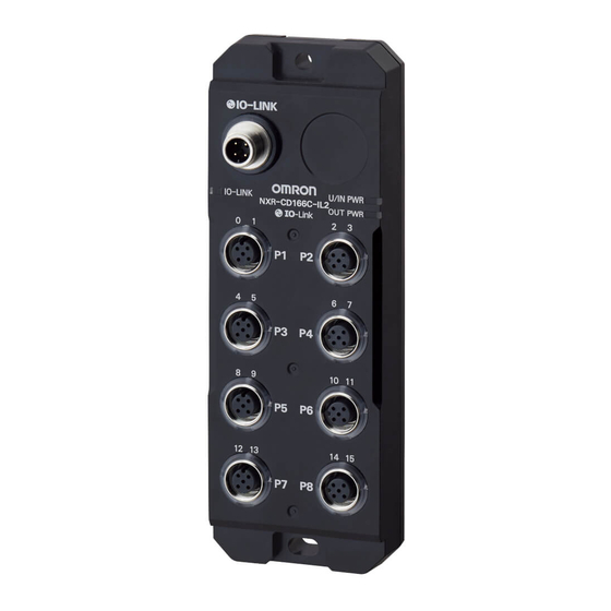
3 Part Names and Functions Parts and Names This section gives the names of the parts of the IO-Link I/O Hubs. Digital I/O Hub NXR-series IO-Link I/O Hub User’s Manual (W620) - Page 45 3 Part Names and Functions Letter Name Function IO-Link connec- The connector for connecting the Hub to the IO-Link Master Unit. • M12 connector (A-coding, male) Connect an IO-Link cable. Applications: • IO-Link communications with the IO-Link Master Unit • Supplying the Unit/input power to the Digital I/O Hub •...
-
Page 46: Indicators
3 Part Names and Functions Indicators This section describes the indicators on the IO-Link I/O Hubs. Refer to 8-3 Checking for Errors and Troubleshooting with the Indicators on page 8-6 for information on troubleshooting. 3-2-1 Status Indicators Digital I/O Hub The indicators depend on the types of Hubs. -
Page 47: I/O Indicators
3 Part Names and Functions Color Status Description Green The Unit/input power is supplied. Not lit The Unit/input power is not supplied. OUT PWR Indicator This indicator shows the status of the output power supply. The indicator is only mounted on the Digital I/O Variable Hub. - Page 48 3 Part Names and Functions Color Status Description Flashing If pin 4 or pin 2 serves as One of the following errors occurred • an input Sensor Disconnected Error occurred to pin 1 • Sensor power supply short-circuit error occurred to pin 1 If pin 4 serves as an out- One of the following errors occurred...
-
Page 49: Connectors
3 Part Names and Functions Connectors This section describes the connectors of the IO-Link I/O Hubs. 3-3-1 IO-Link Connector The IO-Link connector is used for connecting the Hub to the IO-Link Master Unit. Digital I/O Hub The specifications are as follows: •... - Page 50 3 Part Names and Functions Pin No. Pin name Signal name Description Pin 1 Power supply + • • Pin 2 Digital Input Hub: Digital Input Hub: I1, I3 to I15 Input • • Digital I/O Variable Hub: Digital I/O Variable Hub: IO1, IO3 to IO15 Input or output depending on the setting Pin 3...
-
Page 51: Designing The Power Supply System
Designing the Power Supply Sys- This section describes how to design the power supply system for the NXR-series IO- Link I/O Hubs. Power Supply Types and Power Supply System ........4-2 4-1-1 Power Supply Types and Applications ............4-2 4-1-2 Power Supply System .................. -
Page 52: Power Supply Types And Power Supply System
4 Designing the Power Supply System Power Supply Types and Power Sup- ply System This section describes the power supply types and applications and the power supply system for the IO-Link I/O Hubs. 4-1-1 Power Supply Types and Applications This section describes the power supply types and applications for the IO-Link I/O Hubs. Power Supply Types There are the following two types of power supplies that supply power to the IO-Link I/O Hubs. - Page 53 4 Designing the Power Supply System • IO-Link Master Unit Operation Supply the output power from the external power supply, and turn ON the output of pin 2 that you configured. Digital Input Hub The Digital Input Hub does not require the output power to be supplied to the Hub. IO-Link Master Unit Digital Input Hub Connected...
-
Page 54: Designing The Power Supply System
4 Designing the Power Supply System Designing the Power Supply System This section describes how to design the power supply system for the IO-Link I/O Hubs. WARNING Make sure that the voltages and currents that are input to the Hubs are within the specified ranges. -
Page 55: Calculating The Total Current Consumption
4 Designing the Power Supply System For example, for the Digital I/O Variable Hub, confirm that the output power supply voltage is 20.4 to 26.4 VDC. 4-2-3 Calculating the Total Current Consumption The calculation methods for the total current consumption of the Digital I/O Hub from the Unit/input power supply and output power supply are given below. - Page 56 4 Designing the Power Supply System Conditions for Digital I/O Variable Hub Conditions for connected external device I/O connectors Pin name I/O function settings Product name Specification Port 1 to port 5 Pin 4 Input (input current 4.0 Three-wire sensor Current consumption: 30 mA Pin 2 Input (input current 4.0 Three-wire sensor Current consumption: 30 mA...
-
Page 57: Calculating The Voltage Drop
4 Designing the Power Supply System 4-2-4 Calculating the Voltage Drop The calculation methods for the voltage drop in the Unit/input power or the output power supplied from the IO-Link Master Unit are given below. Input Voltage to a Digital I/O Hub = (Voltage of the external power supply connected to the IO-Link Master Unit) - (Voltage drop in the power supply cable and the IO-Link Master Unit) - (Voltage drop in the IO-Link cable) ... - Page 58 4 Designing the Power Supply System Design the system so that the voltage specifications of the IO-Link I/O Hub and connected external devices are met even if the voltage of the Unit/input power supply and output power supply drops. The following shows an example of calculation. Follow the procedure described in this example to calculate voltage drop.
- Page 59 4 Designing the Power Supply System Item Conditions • Voltage specifications of the Digital Unit/input power supply: 20.4 to 26.4 VDC • I/O Variable Hub Output power supply: 20.4 to 26.4 VDC • Voltage specifications of connected Input device: 20.4 to 26.4 VDC external devices •...
-
Page 60: Selecting The External Power Supply And Protective Devices
4 Designing the Power Supply System Selecting the External Power Supply and Protective Devices The IO-Link Master Unit supplies power to the IO-Link I/O Hubs. Refer to the NXR-series IO-Link Master Unit for EtherNet/IP User’s Manual (Cat. No. W619), and select the external power supply and protective devices. -
Page 61: Installation And Wiring
Installation and Wiring This section describes how to install and wire the NXR-series IO-Link I/O Hub. Installing Hubs....................5-2 5-1-1 Installation Precautions ................... 5-2 5-1-2 Installation Orientations................... 5-2 5-1-3 Installation Method ..................5-2 Wiring IO-Link Cable and I/O Cables ............5-4 5-2-1 Installation Precautions ................... -
Page 62: Installing Hubs
5 Installation and Wiring Installing Hubs This section describes how to install the IO-Link I/O Hub. 5-1-1 Installation Precautions To increase the reliability of the IO-Link I/O Hub and take complete advantage of its functionality, ob- serve the following precautions. Do not install the IO-Link I/O Hub in the following locations. - Page 63 5 Installation and Wiring Tightening locations Screw size Tightening torque range Hub mounting holes 1.47 to 1.96 N·m Precautions for Correct Use • Install the Hub properly. The Hub may be affected by vibration if it is not installed properly, which may cause failure.
-
Page 64: Wiring Io-Link Cable And I/O Cables
5 Installation and Wiring Wiring IO-Link Cable and I/O Cables This section describes how to wire the IO-Link cable and I/O cables for the IO-Link I/O Hubs. 5-2-1 Installation Precautions Basic precautions for the installation of IO-Link cable and I/O cables are provided below. •... -
Page 65: Connecting Io-Link Cable
5 Installation and Wiring 5-2-3 Connecting IO-Link Cable This section describes procedures for connecting and disconnecting an IO-Link cable. Procedure for Connecting an IO-Link Cable Use the following procedures to connect an I/O-Link cable. Turn OFF the Unit/input power supply and output power supply to the IO-Link Master Unit before you connect the IO-Link cable. - Page 66 5 Installation and Wiring M12 torque handle Hole of the M12 attachment Mount the M12 attachment on the M12 screw connector of the IO-Link cable. After you mount the M12 attachment, rotate the M12 torque handle in the direction shown in the following figure to tighten the M12 screw connector to the specified torque.
-
Page 67: Connecting I/O Cables
5 Installation and Wiring M12 torque handle Hole of the M12 attachment Mount the M12 attachment on the M12 screw connector of the IO-Link cable. After you mount the M12 attachment, rotate the M12 torque handle in the direction shown in the following figure to loosen the M12 screw connector. - Page 68 5 Installation and Wiring Rotate the M12 screw connector of the I/O cable in the direction shown in the following figure to tighten it. Tighten the connector before tightening it to the specified torque. M12 screw connector Set the M12 torque handle to the specified torque. Then, insert the torque handle into the tight- ening hole of the M12 attachment.
- Page 69 5 Installation and Wiring Mount the M12 attachment on the M12 screw connector of the I/O cable. After you mount the M12 attachment, rotate the M12 torque handle in the direction shown in the following figure to tighten the M12 screw connector to the specified torque. M12 torque handle M12 screw connector M12 attachment...
-
Page 70: Tightening Torque
5 Installation and Wiring M12 torque handle M12 screw connector M12 attachment Rotate the M12 screw connector of the I/O cable in the direction opposite to the connection di- rection. 5-2-5 Tightening Torque Tighten the M12 screw connectors of the IO-Link cable and I/O cables to the following torque. You can maintain the IP67 protective structure when the screw connectors are tightened to a suitable tighten- ing torque. -
Page 71: Wiring Example For I/O Connectors
5 Installation and Wiring Wiring Example for I/O Connectors Wiring examples for connecting the following external devices to the I/O connectors on the Digital I/O Hub are given below. • Two-wire sensor • Three-wire sensor • Output device Wring examples with a branch connector are also shown. 5-11 NXR-series IO-Link I/O Hub User’s Manual (W620) - Page 72 5 Installation and Wiring Precautions for Correct Use If you make the following setting to pin 2 and pin 4 of the port for the Digital I/O Variable Hub and connect the Hub with external devices, use the external devices without protective diodes in the locations shown in the following figure.
- Page 73 5 Installation and Wiring U/IN P+ Reverse IO-Link connector OUT P+ current U/IN P-/OUT P- I/O connector IO-Link Master Unit Reverse current IO white I/O connector Protective diode V brown Pin 4: Input Pin 2: Output Internal IO black circuits G blue Connected external device Reverse current...
- Page 74 Wiring examples of using a branch connector to connect two or more external devices to a port are shown below. Use the following branch connector. • XS5R-D426-1 (OMRON) Refer to Branch Connector for I/O Connectors on page 5-17 in 5-4-2 I/O Cables on page 5-16 for details on the branch connector.
- Page 75 5 Installation and Wiring Two-wire I1 or IO1 sensor I/O connector I0 or IO0 Three-wire Digital I/O Hub sensor with inputs PNP type The power +(V) to pin 1 is supplied from the IO-Link Master Unit through the IO-Link cable to the Digital I/O Hub.
-
Page 76: Connected Devices
Name and appearance Specification connec- Model turer con- tion direc- length tors duc- tion tors XS2W Connector with Cable OMRON M12 socket (A-cod- Screw Straight/ XS2W- (M12 socket/M12 plug) Corpora- ing, female) to connector straight D421- tion M12 plug (A-cod-... -
Page 77: Waterproof Cover For Connectors
XS5R Y-Joint Plug/Socket Con- OMRON Smartclick XS5R- nector Corpora- D426-1 connector tion I/O connectors for the IO-Link I/O Hubs are not Smartclick connectors. Use I/O cable tightening tools to install this ca- ble. - Page 78 5 Installation and Wiring Name and appear- Available connec- Manufacturer Specification Model ance tors M12 Waterproof OMRON Corpora- Screw connector XS2Z-22 Cover tion 5-18 NXR-series IO-Link I/O Hub User’s Manual (W620)
-
Page 79: Process Data And Service Data
Process Data and Service Data This section describes process data and service data of the NXR-series IO-Link I/O Hubs. Process Data ....................6-2 6-1-1 Digital Input Hub....................6-2 6-1-2 Digital I/O Variable Hub ................... 6-4 Service Data....................6-9 6-2-1 Digital I/O Hub ....................6-9 NXR-series IO-Link I/O Hub User’s Manual (W620) -
Page 80: Process Data
6 Process Data and Service Data Process Data This section describes the process data of each type of IO-Link I/O Hubs. 6-1-1 Digital Input Hub The Digital Input Hub has only process input data. Process Input Data of Digital Input Hub The data structure is shown below. - Page 81 6 Process Data and Service Data Assignment Description PD0 0 Port1 Pin4 Input Bit 1: The relevant input is ON. 0: The relevant input is OFF. Port1 Pin2 Input Bit Port2 Pin4 Input Bit Port2 Pin2 Input Bit Port3 Pin4 Input Bit Port3 Pin2 Input Bit Port4 Pin4 Input Bit Port4 Pin2 Input Bit...
-
Page 82: Digital I/O Variable Hub
6 Process Data and Service Data Port£ Status The data indicate the detailed status of each port. £ refers to port numbers 1 to 8. Assignment Description Port£ Sensor Disconnec- 1: A sensor disconnection was detected. tion Detection Bit 0: A sensor disconnection was not detected. - Page 83 6 Process Data and Service Data 7 6 5 4 3 2 1 0 PD18 Port8 Status PD19 The following describes each data in detail. The value 1 indicates TRUE and 0 indicates FALSE. Input Data The data indicate the input status of each port. Assignment Description PD0 0...
- Page 84 6 Process Data and Service Data Assignment Description PD2 0 Unit/Input Pow- 1: The Unit/input power supply voltage is below the monitored voltage. er Supply Volt- 0: The Unit/input power supply voltage is equal to or higher than the moni- age Drop De- tored voltage.
- Page 85 6 Process Data and Service Data Assignment Description Port£ Sensor Disconnec- 1: A sensor disconnection was detected. tion Detection Bit 0: A sensor disconnection was not detected. Port£ Sensor Short Circuit 1: A sensor power supply short circuit was detected. Detection Bit 0: A sensor power supply short circuit was not detected.
- Page 86 6 Process Data and Service Data Output Data The data indicate the output status of each port. Bit Assignment Description PD0 0 Port1 Pin4 1: The relevant output is ON. Output Bit 0: The relevant output is OFF. If a contact is set to input through the I/O function configuration, setting the con- Port1 Pin2 tact to 1 does not turn ON the output.
-
Page 87: Service Data
(Dec) (Byte) System-Com- UInteger W 05 hex: mand Parameter upload start 82 hex: Restore factory set- ting Vendor Name String OMRON Corpora- tion Vendor Text String OMRON Corpora- tion Product Name String Each product model Product ID String Each product... - Page 88 6 Process Data and Service Data • For the Digital Input Hub: NXR-ID166C-IL2 • For the Digital I/O Variable Hub: NXR-CD166C-IL2 Vendor Specific Subin- Data Back- Index For- Selectable length fault Remarks Item (Dec) cess range (Byte) value (Dec) Port£ Pin4 I/O Setting ¡...
- Page 89 6 Process Data and Service Data Subin- Data Back- Index For- Selectable length fault Remarks Item (Dec) cess range (Byte) value (Dec) Port£ Sensor Short Record W 01 hex 01 hex: £ Circuit Detection Hold Reset Reset Power Supply Voltage UIn- 01 hex 01 hex:...
- Page 90 6 Process Data and Service Data 6-12 NXR-series IO-Link I/O Hub User’s Manual (W620)
-
Page 91: Functions Of Io-Link I/O Hubs
Functions of IO-Link I/O Hubs This section describes the functions of the NXR-series IO-Link I/O Hubs. Functions of Digital I/O Hubs ................ 7-2 7-1-1 I/O Function..................... 7-2 7-1-2 I/O Cable Disconnection Detection ..............7-3 7-1-3 I/O Cable Short-circuit Detection..............7-6 7-1-4 All Hold Bits Reset................... -
Page 92: Functions Of Digital I/O Hubs
7 Functions of IO-Link I/O Hubs Functions of Digital I/O Hubs 7-1-1 I/O Function This section describes the I/O function. Overview and Applications This function enables you to set pin 4 and pin 2 of each port to input or output, depending on the devi- ces connected to the Digital I/O Variable Hub. -
Page 93: I/O Cable Disconnection Detection
7 Functions of IO-Link I/O Hubs Double-click or right-click the device DTM for the Digital I/O Variable Hub to configure, and then select Configuration. The Configuration tab page is displayed. In the Configuration tab page, Menu is displayed with Parameter selected. Refer to A-4 Configuration Tab Page on page A-6 for details on the Configuration tab page. - Page 94 7 Functions of IO-Link I/O Hubs Precautions for Correct Use • The sensor disconnection detection detects the disconnection of the power line to the three- wire sensor but cannot detect the disconnection of the signal line. • Depending on the connected sensor or the connected external load, the detection function may falsely detect disconnection as follows: For sensor disconnection detection The detection function falsely detects disconnection when an input device whose current con-...
- Page 95 7 Functions of IO-Link I/O Hubs How the Disconnection Detection Works If the function detects disconnection, the following bits of process input data turn ON and the I/O Cable Disconnection (7701 hex) device event occurs. Also, the status appears in the Pin 4/Pin 1 status indicator or Pin 2 status indicator.
-
Page 96: I/O Cable Short-Circuit Detection
7 Functions of IO-Link I/O Hubs Refer to 7-1-4 All Hold Bits Reset on page 7-8 for information on executing all hold bits reset. c. Cycle the Unit/input power supply Setting Method The following describes how to configure the function from CX-ConfiguratorFDT. Refer to Setting IO- Link Devices with the CX-ConfiguratorFDT in the NXR-series IO-Link Master Unit for EtherNet/IP User’s Manual (Cat. - Page 97 7 Functions of IO-Link I/O Hubs Applicable Hubs • Sensor power supply short circuit detection All models of the Digital I/O Hub • External load short circuit detection Digital I/O Variable Hub only Function Details This function detects sensor power supply short circuit from input and external load short circuit from output.
-
Page 98: All Hold Bits Reset
7 Functions of IO-Link I/O Hubs The Pin 4/Pin 1 status indicator or the Pin 2 status indicator operates according to the status of each relevant short circuit detection bit. The short circuit detection hold bits are irrelevant to indica- tor display. -
Page 99: Voltage Drop Detection For Unit/Input Power Supply
7 Functions of IO-Link I/O Hubs Overview and Applications This function resets all hold bits for detection of disconnection, short-circuit, and power supply voltage drop that occur to the Digital I/O Hub. Applicable Hubs All models of the Digital I/O Hub Function Details This function resets all error detection hold bits of the Digital I/O Hub. - Page 100 7 Functions of IO-Link I/O Hubs Overview and Applications This function monitors the Unit/input power supply voltage fed to the Digital I/O Hub, and detects volt- age drop when the voltage decreases below the monitored voltage. Applicable Hubs All models of the Digital I/O Hub Function Details This function detects voltage drop when the voltage is certainly below the lower limit for the Unit/input power supply.
-
Page 101: Voltage Drop Detection For Output Power Supply
7 Functions of IO-Link I/O Hubs Service data Index (Dec) Subindex (Dec) Power Supply Voltage Drop Detection Hold Reset 79 b. Execute all hold bits reset Refer to 7-1-4 All Hold Bits Reset on page 7-8 for information on executing all hold bits reset. c. -
Page 102: Digital Input Filter
7 Functions of IO-Link I/O Hubs On the other hand, the Output Power Supply Voltage Drop Detection Hold Bit remains ON after the cause of the power supply voltage drop is removed. Refer to Turning OFF the Power Supply Volt- age Drop Detection Hold Bit on page 7-12 for how to turn off the bits. - Page 103 7 Functions of IO-Link I/O Hubs Function Details This function reads inputs (ON or OFF) during a set time. When all readings are the same (all readings are ON or all readings are OFF), this function turns ON or OFF the input value. When an input changes from OFF to ON (or from ON to OFF), this function starts reading the input from the moment four times at an interval of a quarter of the set time.
-
Page 104: Communications Error Output Setting
7 Functions of IO-Link I/O Hubs Refer to the NXR-series IO-Link Master Unit for EtherNet/IP User’s Manual (Cat. No. W619) for details on how to configure the function through message communications. Setting Method The following describes how to configure the function from CX-ConfiguratorFDT. Refer to Setting IO- Link Devices with the CX-ConfiguratorFDT in the NXR-series IO-Link Master Unit for EtherNet/IP User’s Manual (Cat. -
Page 105: Monitoring Total Power-On Time
7 Functions of IO-Link I/O Hubs Function Details The following item configure the output operation for occurrence of communications errors. Default val- Description Setting range Unit Update timing Setting Port£ Error Mode Sets each port to hold the pre-er- 00 hex 00 hex: Immediately Output Setting... - Page 106 7 Functions of IO-Link I/O Hubs Overview and Applications This function records the time period during which the Unit/input power is supplied to the Digital I/O Hub, and displays the period as the operating hours of the Hub. Applicable Hubs All models of the Digital I/O Hub Function Details The following shows the specifications of the monitoring total power-ON time.
- Page 107 7 Functions of IO-Link I/O Hubs Checking through Message Communications Read the following service data through message communications. Refer to the NXR-series IO- Link Master Unit for EtherNet/IP User’s Manual (Cat. No. W619) for how to read through message communications.
- Page 108 7 Functions of IO-Link I/O Hubs 7-18 NXR-series IO-Link I/O Hub User’s Manual (W620)
-
Page 109: Troubleshooting
Troubleshooting This section describes troubleshooting for the NXR-series IO-Link I/O Hubs. Error Notification Methods ................8-2 Checking for Errors ..................8-4 Checking for Errors and Troubleshooting with the Indicators ....8-6 8-3-1 Status Indicators....................8-6 8-3-2 I/O Indicators ....................8-7 Checking for Errors and Troubleshooting with the Device Events ... -
Page 110: Error Notification Methods
8 Troubleshooting Error Notification Methods This section shows an example of system configuration where an NXR-series IO-Link Master Unit for EtherNet/IP is connected to an IO-Link I/O Hub and describes the methods of error notification. The IO-Link I/O Hub notifies an error to the IO-Link Master Unit by the following methods. Refer to 8-2 Checking for Errors on page 8-4 for how to check the notified error. - Page 111 8 Troubleshooting Error notifi- Overview Notification method cation type IO-Link I/O Device events (errors The Hub cyclically sends information on occurrence of device events Hub device or warnings) that the through IO-Link communications to the IO-Link Master Unit. events IO-Link I/O Hub de- The sent information is reflected in the following I/O data of the IO-Link tects.
-
Page 112: Checking For Errors
8 Troubleshooting Checking for Errors This section uses the example of system configuration shown in the Error Notification Methods and describes how to check for errors. You can check for errors that the IO-Link I/O Hub detects with the following methods. Check Detailed Device Status of IO-Link device through message communications instruction... - Page 113 8 Troubleshooting Checking method What you can check Checking device CX-ConfiguratorFDT can read device events. events Also, you can read Detailed Device Status of the service data with the message communi- cations instruction from the Controller. NXR-series IO-Link I/O Hub User’s Manual (W620)
-
Page 114: Checking For Errors And Troubleshooting With The Indicators
8 Troubleshooting Checking for Errors and Trouble- shooting with the Indicators This section describes how to check for errors with the indicators of the IO-Link I/O Hub and trouble- shoot the errors. 8-3-1 Status Indicators Digital I/O Hub U/IN IO-Link Hub status Cause Correction... -
Page 115: I/O Indicators
8 Troubleshooting 8-3-2 I/O Indicators Digital I/O Hub Digital Input Hub Pin 4/Pin 1 status Pin 2 status Hub status Cause Correction Yellow Yellow Red Pin 4 input is ON Flashing Sensor Disconnected Error The I/O cable is Check the I/O cable to occurred to pin 1 broken. - Page 116 8 Troubleshooting Pin 4/Pin 1 sta- Pin 2 status Hub status Cause Correction Yel- Yel- Flash- When pin 4 or Sensor Discon- The I/O ca- Check the I/O ca- pin 2 is set to nected Error oc- ble is bro- ble to see if it is input curred to pin 1...
-
Page 117: Checking For Errors And Troubleshooting With The Device Events
8 Troubleshooting Checking for Errors and Trouble- shooting with the Device Events The IO-Link I/O Hub registers an error that occurs to itself as a device event. Occurrence of a device event is notified to the IO-Link Master Unit and then reflected in the following I/O data of the IO-Link Master Unit. - Page 118 8 Troubleshooting The relevant device goes online. Devices in the Network View are displayed in bold while you are online. In the Configuration tab page, click Diagnosis under Menu. Expand Detailed Device Status. Right-click the device DTM and select Load from device. Registered device events are displayed in Value.
-
Page 119: List Of Device Events And Troubleshooting
8 Troubleshooting 8-4-3 List of Device Events and Troubleshooting The list of registered device events and corrections is as below. IO-Link CX-Configura- event Event name Type Description Correction torFDT display code 5000 Hardware Error Appeared: Error The Non-volatile Mem- Cycle the Unit/input power supply to the Error Device hardware ory Hardware Error was... -
Page 120: Resetting Errors
8 Troubleshooting Resetting Errors Different types of errors that occur to the IO-Link I/O Hub require different reset procedures. The following shows procedures to reset each error. Error name Reset procedure Hardware Er- Cycle the Unit/input power supply to the IO-Link I/O Hub. If this error persists after you cycle the power supply, replace the IO-Link I/O Hub. -
Page 121: Inspection And Maintenance
Inspection and Maintenance This section describes inspection and maintenance of the NXR-series IO-Link I/O Hubs. Cleaning and Inspection................9-2 9-1-1 Cleaning ......................9-2 9-1-2 Inspection Procedure ..................9-2 Maintenance Procedure................. 9-4 9-2-1 Handling an IO-Link I/O Hub to Replace ............9-4 9-2-2 Replacing an IO-Link I/O Hub ................. -
Page 122: Cleaning And Inspection
9 Inspection and Maintenance Cleaning and Inspection This section describes daily device maintenance such as cleaning and inspection. Inspect the IO-Link I/O Hub daily or periodically in order to keep it in optimal operating condition. 9-1-1 Cleaning Clean the device regularly as described below in order to keep it in optimal operating condition. •... - Page 123 9 Inspection and Maintenance Item Inspection Criteria Tool Environment Check the ambient temperature and the tem- -10 to 55°C Thermometer perature inside the panel Check the ambient humidity and the humidity 25% to 85% (with no Hygrometer inside the panel condensation) Check for accumulation of dust No accumulation of...
-
Page 124: Maintenance Procedure
• After replacement, check that there are no problems with the new device. • When you return a faulty device for repair, send the device to your OMRON representative with a note describing your problem in as much detail as possible. -
Page 125: Appendices
Appendices This section describes version-related information of the NXR-series IO-Link I/O Hubs and considerations for connecting two-wire DC sensors. Version Information ..................A-2 Considerations for Connecting a Two-wire DC Sensor......A-3 Wiring Precautions for External Output Signal Lines........ A-5 Configuration Tab Page ................A-6 NXR-series IO-Link I/O Hub User’s Manual (W620) -
Page 126: A-1 Version Information
Appendices A-1 Version Information This section describes the relationship between the unit versions of the IO-Link I/O Hubs and the NXR-series IO-Link I/O Master Unit for EtherNet/IP and the versions of the Support Software. If you use any of the combinations of versions/unit versions that are the same or that are later or higher than the corresponding versions given in the following table, you can use all of the functions that are sup- ported by that unit version of the IO-Link I/O Hub. -
Page 127: Considerations For Connecting A Two-Wire Dc Sensor
Appendices A-2 Considerations for Connecting a Two- wire DC Sensor When you use a two-wire DC sensor with your IO-Link I/O Hub, check that the following conditions are met. Failure to meet these conditions may result in operating errors. Relation between ON Voltage of the IO-Link I/O Hubs and Sensor Residual Voltage The IO-Link I/O Hubs cannot detect sensor output ON without the following conditions met: ≤... - Page 128 Appendices I/O connector Two-wire sensor Relation between OFF Current of the IO-Link I/O Hubs and Sensor Leakage Current The IO-Link I/O Hubs cannot detect sensor output OFF without the following conditions met: ≥ I leak : OFF current to the input of the IO-Link I/O Hub : Sensor leakage current leak When I...
-
Page 129: Wiring Precautions For External Output Signal Lines
Appendices A-3 Wiring Precautions for External Out- put Signal Lines Observe the following points when wiring external output signal lines. • To absorb counter-electromotive force when an inductive load is connected to an output signal, con- nect a diode near the inductive load. Example: When pin 4 is used for output I/O connector Diode... -
Page 130: A-4 Configuration Tab Page
Appendices A-4 Configuration Tab Page The following shows the IO-Link I/O Hub Configuration tab page of CX-ConfiguratorFDT. Letter Description From Menu, select Parameter to display the IO-Link I/O Hub Configuration tab page. The IO-Link I/O Hub settings. To configure a setting, expand it. The values of the settings. - Page 131 Index NXR-series IO-Link I/O Hub User’s Manual (W620)
- Page 132 Index Index M12 attachment..............5-4 M12 torque handle.............5-4 back up................9-4 baud rate................2-3 branch connector.............5-17 non-IO-Link connected external device......1-6 Non-volatile Memory Write Error........8-11 C/Q..................3-7 connected external devices..........22 ON delay time..............7-13 controller................1-5 OUT P-................3-7 current consumption from output power supply....4-5 OUT P+................3-7 current consumption from Unit/input power supply...
- Page 134 The Netherlands Hoffman Estates, IL 60169 U.S.A. Tel: (31)2356-81-300/Fax: (31)2356-81-388 Tel: (1) 847-843-7900/Fax: (1) 847-843-7787 © OMRON Corporation 2020 All Rights Reserved. OMRON (CHINA) CO., LTD. OMRON ASIA PACIFIC PTE. LTD. In the interest of product improvement, Room 2211, Bank of China Tower, No.
Need help?
Do you have a question about the NXR Series and is the answer not in the manual?
Questions and answers