Table of Contents
Advertisement
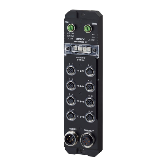
Environment-resistive Remote Terminal NXR-series IO-Link Master Unit for EtherNet/IP
NXR-ILM08C-EIT
Streamline commissioning and maintenance of production equipment.
Simple, easy, and quick - Reduce Availability Loss and Quality Loss!
Features
• IP67 protection
• Replacement without software
• Ethernet cable diagnostics
Reports approximate locations of disconnections or short circuits in Ethernet cables
• Communication quality of EtherNet/IP
Records the total number of received FCS errors which allows checking communication quality
• Communication quality of IO-Link
Records the total number of lost frames which allows checking communication quality
• Location of short circuits
Detects and protects from short circuits in connection to IO-Link devices or standard devices
• Power supply voltage monitoring
Monitors power supply voltage for the unit and inputs and power supply voltage for outputs
• Power OUT connector for through-wiring for power supply
• Built-in L2 switching hub for through-wiring for Ethernet
TM
CSM_NXR-ILM08C-EIT_DS_E_1_2
1
Advertisement
Table of Contents

Related Manuals for Omron NXR-ILM08C-EIT


Summary of Contents for Omron NXR-ILM08C-EIT
- Page 1 Environment-resistive Remote Terminal NXR-series IO-Link Master Unit for EtherNet/IP NXR-ILM08C-EIT CSM_NXR-ILM08C-EIT_DS_E_1_2 Streamline commissioning and maintenance of production equipment. Simple, easy, and quick - Reduce Availability Loss and Quality Loss! Features • IP67 protection • Replacement without software • Ethernet cable diagnostics Reports approximate locations of disconnections or short circuits in Ethernet cables •...
-
Page 2: System Configuration
NXR-ILM08C-EIT System Configuration System Configuration (A) Controller (B) EtherNet/IP scanner (N) Support Software for the Controller EtherNet/IP port (I) Communications cable EtherNet/IP cable (L) Network Configurator (C) EtherNet/IP adapter: NXR-series EtherNet/IP IO-Link (M) EDS files Master Unit (H) Ethernet switch... - Page 3 The components are described in the table below. Letter Name Function This is an OMRON CPU Unit or a controller from another company, connected to the Controller IO-Link Master Unit through an EtherNet/IP adapter. The EtherNet/IP scanner monitors the status of the connections with EtherNet/IP...
-
Page 4: Ordering Information
NXR-ILM08C-EIT Ordering Information Applicable standards Refer to the OMRON website (www.ia.omron.com) or ask your OMRON representative for the most recent applicable standards for each model. NXR-series IO-Link Master Unit for EtherNet/IP Product name Number of IO-Link ports Degree of protection... - Page 5 NXR-ILM08C-EIT EtherNet/IP Communications Cables Ethernet communications cables to connect the IO-Link master unit. Connection Cables between IO-Link Master Unit and EtherNet/IP Scanner with RJ45 Connectors Cable No. of cable Cable Name and appearance Manufacturer Specification Connector connection Model conductors length direction 0.5 m...
- Page 6 NXR-ILM08C-EIT I/O Cables • Conversion Cable The following cable converts connections from an IO-Link device or non-IO-Link connected external device with an M8 plug. Cable No. of cable Cable Name and appearance Manufacturer Specification Connector connection Model conductors length direction...
-
Page 7: General Specifications
Insulation resistance 20 MΩ min. (between isolated circuits) Applicable standards *1 EU: EN 61131-2, RCM, KC, IO-Link conformance, EtherNet/IP conformance *1. Refer to the OMRON website (www.ia.omron.com) or ask your OMRON representative for the most recent applicable standards for each model. - Page 8 NXR-ILM08C-EIT EtherNet/IP Communications Specifications Item Specification EtherNet/IP protocol Communications protocols • Implicit messages (Class1) • Explicit messages (Class 3, UCMM) Modulation Baseband Link speed 10 Mbps or 100 Mbps 100BASE-TX or 10BASE-T (100BASE-TX is recommended.) *1 Ethernet physical layer Ethernet switch...
-
Page 9: Unit Specifications
NXR-ILM08C-EIT Unit Specifications Item Specification IO-Link connector type Class A Number of ports COM1: 4.8 kbps Baud rate COM2: 38.4 kbps IO-Link specifications COM3: 230.4 kbps • Cable type : Unshielded • Cable length : 20 m max. Cable specifications •... - Page 10 NXR-ILM08C-EIT Item Specification Power supply used Output power supply Internal I/O common Output type Open-drain Rated voltage 24 VDC (20.4 to 26.4 VDC) Digital outputs for pin 4 or Maximum load current 2 A/pin digital outputs for pin 2 Leakage current 0.1 mA max.
-
Page 11: Version Information
NXR-ILM08C-EIT Version Information The following table shows the relationship between the unit versions of the IO-Link Master Unit and CPU unit, and the corresponding support software versions. Connecting with NJ/NX CPU Unit NX-series CPU Unit IO-Link Master Unit Corresponding versions... -
Page 12: External Interface
NXR-ILM08C-EIT External Interface Letter Name Function The connector for EtherNet/IP port 1. EtherNet/IP communications • M12 connector (D-coding, female) connector 1 Connect a communications cable. The connector for EtherNet/IP port 2. EtherNet/IP communications • M12 connector (D-coding, female) connector 2 Connect a communications cable. - Page 13 NXR-ILM08C-EIT Dimensions (Unit: mm) 45.5 Mounting dimensions 32.8 16.5 19.2 Two, M5 or 5.3-dia. holes 26.7 97.7 122.7 147.7 172.7 208.7 227 ±0.2 14.5 19.2 24.2 26.8 47.5 14.2...
- Page 14 NXR-ILM08C-EIT Wiring Example for I/O connectors Wiring Example for IO-Link Devices Wiring Example for IO-Link Devices (with Digital Inputs for Pin 2) A wiring example for an IO-Link device with digital inputs for pin 2 is shown below. In this example, the port is used in the following communications modes.
- Page 15 NXR-ILM08C-EIT Wiring Example for IO-Link Devices (without Digital Inputs and Outputs for Pin 2) A wiring example for an IO-Link device without digital inputs and outputs for pin 2 is shown below. In this example, the port is used in the following communications modes.
- Page 16 NXR-ILM08C-EIT Wiring Example for Non-IO-Link Input Devices Wiring Example for Three-wire Sensors In this example, the port is used in the following communications modes. Pin 4: SIO (DI) Mode, pin 2: Disabled U/IN P+ Unit/input power supply U/IN P- Power supply connector (input)
- Page 17 NXR-ILM08C-EIT Wiring Example for Non-IO-Link Output Devices A wiring example between the IO-Link Master Unit and a non-IO-Link output device is shown below. In this example, the port is used in the following communications modes. Pin 4: SIO (DO) Mode, pin 2: Disabled...
-
Page 18: Power Supply System
NXR-ILM08C-EIT Power Supply System There are two methods to supply power to IO-Link Master Units as shown below. Direct power supply Description Feature Connect the external power supplies to the power supply connector (input) of each IO-Link Master Unit. The power supply connector (output) is not used. - Page 19 NXR-ILM08C-EIT Power supply with through wiring Description Feature Connect the external power supplies to the power supply connector (input) of one IO-Link Master Unit. Then, connect the power supply connector (output) of the Unit to the power supply connector (input) of another IO-Link Master Unit with a power supply cable. In this way, supply power with through-wiring between the subsequent Units with power supply cables.
-
Page 20: Related Manuals
• Event functions Sysmac is a trademark or registered trademark of OMRON Corporation in Japan and other countries for OMRON factory automation products. Microsoft and Windows are either registered trademarks or trademarks of Microsoft Corporation in the United Status and/or other countries. - Page 21 (a) Exclusive Warranty. Omron’s exclusive warranty is that the Products will be free from defects in materials and workmanship for a period of twelve months from the date of sale by Omron (or such other period expressed in writing by Omron). Omron disclaims all other warranties, express or implied.
Need help?
Do you have a question about the NXR-ILM08C-EIT and is the answer not in the manual?
Questions and answers