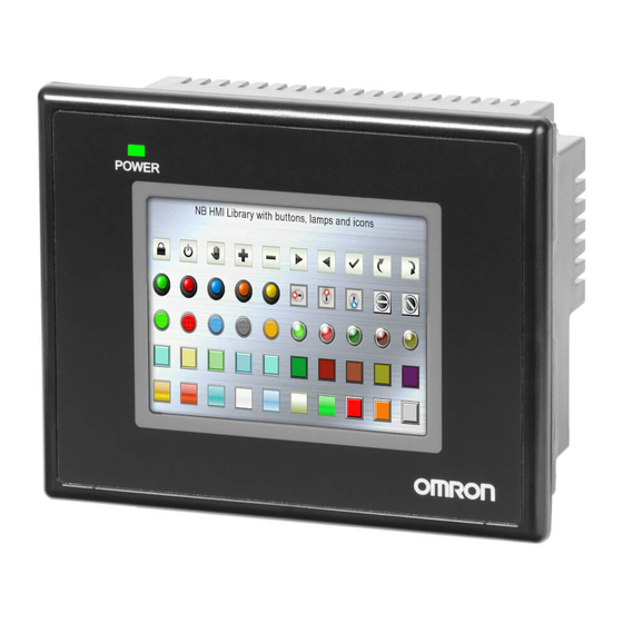
Omron NB3Q-TW00B Setup Manual
Nb-series programmable terminal
Hide thumbs
Also See for NB3Q-TW00B:
- Operation manual (548 pages) ,
- Startup manual manual (126 pages) ,
- Service manual (38 pages)

Related Manuals for Omron NB3Q-TW00B


Summary of Contents for Omron NB3Q-TW00B
- Page 1 Cat. No. V107-E1-04 NB-series NB3Q-TW NB5Q-TW NB7W-TW NB10W-TW01B Programmable Terminals SETUP MANUAL WWW.NNC.IR...
- Page 2 OMRON. No patent liability is assumed with respect to the use of the information contained herein. Moreover, because OMRON is con- stantly striving to improve its high-quality products, the information contained in this manual is subject to change without notice.
- Page 3 NB-series NB3Q-TW NB5Q-TW NB7W-TW NB10W-TW01B Programmable Terminals Setup Manual Revised August 2012 WWW.NNC.IR...
-
Page 4: Introduction
OMRON representative. • Make sure that the ratings and performance characteristics of the product are sufficient for the systems, machines, and equipment, and be sure to provide the systems, machines, and equipment with double safety mechanisms. -
Page 5: Nb-Series Manuals
NB-series Manuals NB-series manuals are organized in the sections listed in the following tables. Refer to the appropriate section in the manuals as required. Programmable Terminals Setup Manual (Cat. No. V107) (This Manual) Section Contents Section 1 Part Names and Functions This section describes the names and functions of the various parts of an NB Unit. - Page 6 Programmable Terminals Host Connection Manual (Cat. No. V108) Section Contents Section 1 List for All PLCs This section lists all PLCs supported by NB Units. Supported by NB series Section 2 Connecting to SIEMENS This section describes the connection to SIEMENS PLCs. PLCs Section 3 Connecting to Mitsubishi This section describes the connection to Mitsubishi PLCs.
-
Page 7: Manual Structure
Page tab procedure. Height Gives the number Opening dimensions of the section. Models Opening Dimension (W H mm) NB3Q-TW00B/TW01B 119.0(+0.5/-0) 93.0(+0.5/-0) NB5Q-TW00B/TW01B 172.4(+0.5/-0) 131.0(+0.5/-0) NB7W-TW00B/TW01B 191.0(+0.5/-0) 137.0(+0.5/-0) NB10W-TW01B 258.0(+0.5/-0) 200.0(+0.5/-0) As follows, insert panel fixators at the locations indicated by red box around the back of the NB Unit. -
Page 8: Terminology
Indicates a Serial Communication Board for an OMRON SYSMAC CS/CJ-Series PLC. Board Communication Board Indicates a Communication Board for an OMRON C200HX/HG/HE(-Z) PLC. CPU Unit Indicates a CPU Unit in the OMRON CP, CS/CJ or SYSMAC C Series of Programmable Controllers. NB-Designer Indicates the OMRON NB-Designer. Host Indicates the PLC and other units functioning as the control devices for NB-Series Units. - Page 9 NB-series Programmable Terminals Setup Manual(V107) WWW.NNC.IR...
-
Page 10: Table Of Contents
CONTENTS Introduction....................... 1 NB-series Manuals....................2 Manual Structure ...................... 4 Terminology ......................5 Safety Precautions ....................12 Precautions for Safe Use ..................14 Precautions for Correct Use .................. 16 Conformance to EC Directives ................17 Related Manuals ..................... 18 Sec. 1 Part Names and Functions............ - Page 11 A-4-2 Soldering...........................A-10 A-4-3 Shield Assembly........................A-10 A-4-4 Method for Fabricating the Cable for Connection to OMRON PLC ...........A-11 A-4-5 Method for fabricating the cable for connection to PC ..............A-13 A-5 List of Models ........................A-14 A-6 List of Options ........................A-19 Revision History ......................1 NB-series Programmable Terminals Setup Manual(V107) WWW.NNC.IR...
- Page 12 WHETHER SUCH CLAIM IS BASED ON CONTRACT, WARRANTY, NEGLIGENCE, OR STRICT LIABILITY. In no event shall the responsibility of OMRON for any act exceed the individual price of the product on which liability is asserted. IN NO EVENT SHALL OMRON BE RESPONSIBLE FOR WARRANTY, REPAIR, OR OTHER CLAIMS REGARDING THE PRODUCTS UNLESS OMRON’S ANALYSIS CONFIRMS THAT THE PRODUCTS...
- Page 13 Application Considerations SUITABILITY FOR USE OMRON shall not be responsible for conformity with any standards, codes, or regulations that apply to the combination of products in the customer’s application or use of the products. At the customer’s request, OMRON will provide applicable third party certification documents identifying ratings and limitations of use that apply to the products.
- Page 14 Performance data given in this manual is provided as a guide for the user in determining suitability and does not constitute a warranty. It may represent the result of OMRON’s test conditions, and the users must correlate it to actual application requirements. Actual performance is subject to the OMRON Warranty and Limitations of Liability.
-
Page 15: Safety Precautions
Safety Precautions Notation Used for Safety Information The following notation is used in this manual to provide precautions required to ensure safe usage of the product. The safety precautions that are provided are extremely important to safety. Always read and heed the information provided in all safety precautions. Indicates an imminently hazardous situation which, WARNING if not avoided, will result in death or serious injury. - Page 16 WARNING Do not attempt to take the product apart and do not touch the product inside while the power is being supplied. Otherwise it may result in electric shock. Always ensure that the personnel in charge confirm that installation, inspection, and maintenance were properly performed for the NB Unit.
-
Page 17: Precautions For Safe Use
NB unit is +5V±5%, and the maximum current is 250mA. (The serial communication port COM1 of NB3Q-TW00B and NB3Q-TW01B is unable to output the current.) • Turn OFF the power supply before connecting or disconnecting cables. - Page 18 • Do not dispose the Units together with general waste at waste yards. When disposing them, follow the related local ordinances or rules. • Customers may not replace the backlight lamp inside the NB Unit. Please contact OMRON’s customer service center.
-
Page 19: Precautions For Correct Use
Precautions for Correct Use • Do not install the unit in any of the following locations: Locations subject to severe changes in temperature Locations subject to temperatures or humidity outside the range specified in the specifications Locations subject to condensation as the result of high humidity Locations subject to corrosive or flammable gases Locations subject to strong shock or vibration Locations outdoors subject to direct wind and rain... -
Page 20: Conformance To Ec Directives
OMRON products are electronic devices that are incorporated in machines and manufacturing installations. OMRON PTs conform to the related EMC Directives (see note) so that the devices and machines into which they are built can more easily conform to EMC Directives. The actual products have been through inspections and are completely in accordance with EMC directives. -
Page 21: Related Manuals
Related Manuals The related manuals are as follows: Devices and Software Manual Name Manual No. NB series NB Series NB-Designer Operation Manual V106 NB Series Setup Manual (This manual) V107 NB Series Host Connection Manual V108 NB Series Startup Guide V109 SYSMAC CP Series CP1L CPU Unit Operation Manual W462... -
Page 22: Part Names And Functions
Part Names and Functions This section describes the names and functions of the various parts of an NB Unit. 1-1 Part Names ........... 1-2 1-2 Part Specifications . -
Page 23: Part Names
1 Part Names and Functions Part Names NB3Q-TW00B/NB3Q-TW01B model Front view Power Indicator Display Back view : NB -TW01B only Precautions for Safe Use Confirm the safety of the system before turning ON or OFF the power supply, or pressing the reset button. - Page 24 1 Part Names and Functions NB5Q-TW00B/NB5Q-TW01B model Front view Power Indicator Display Back view : NB -TW01B only Precautions for Safe Use Confirm the safety of the system before turning ON or OFF the power supply, or pressing the reset button. NB-series Programmable Terminals Setup Manual(V107) WWW.NNC.IR...
- Page 25 1 Part Names and Functions NB7W-TW00B/NB7W-TW01B model Front view Power Indicator Display Back view : NB -TW01B only Precautions for Safe Use Confirm the safety of the system before turning ON or OFF the power supply, or pressing the reset button. NB-series Programmable Terminals Setup Manual(V107) WWW.NNC.IR...
- Page 26 1 Part Names and Functions NB10W-TW01B model Front view Power Indicator Display Back view Precautions for Safe Use Confirm the safety of the system before turning ON or OFF the power supply, or pressing the reset button. NB-series Programmable Terminals Setup Manual(V107) WWW.NNC.IR...
-
Page 27: Part Specifications
1 Part Names and Functions Part Specifications Touch Panel Input operation can be carried out by means of the touch panel. By pressing the touch panel, the screens can be switched, and the contact information can be transmitted to the host. WARNING Do not use the input functions of the touch switch, etc. - Page 28 1 Part Names and Functions Precautions for Safe Use When using the No. 6 pin of the serial communications port COM1 connector for a voltage of DC+5V, make sure the supply equipment’s current capacity is below 250 mA before using it. The DC+5V voltage output of the NB Unit is +5V±5%, and the maximum current is 250 mA.
- Page 29 1 Part Names and Functions USB HOST -TW01B is equipped with USB HOST port, which is USB A-type port. Through this port, USB memory can be connected to perform uploading, downloading, project operation and storage of related data. And its pins are defined as follows: Pins Signals Functions...
- Page 30 1 Part Names and Functions DIP Switch NB5Q/NB7W only has 2 switches SW1 and SW2, while for the NB3Q and NB10W, there are totally 4 DIP switches, and for all models, SW1 and SW2 feature the same functions. The settings and corresponding operating modes are as follows: Operating modes System Setting Mode...
- Page 31 1 Part Names and Functions 1-10 NB-series Programmable Terminals Setup Manual(V107) WWW.NNC.IR...
-
Page 32: Installing The Nb Unit And Connecting Peripheral Devices
Ü Installing the NB Unit and Connecting Peripheral Devices This section describes the methods used to install the NB Unit and connect peripheral devices. 2-1 Installing the NB Unit ......... . . 2-2 2-1-1 Installation environment . -
Page 33: Installing The Nb Unit
2 Installing the NB Unit and Connecting Peripheral Devices Installing the NB Unit This section describes the methods used to mount the NB Unit onto an operation panel and connect the power supply. 2-1-1 Installation environment When mounting the NB Unit onto the operation panel, pay attention to the following precautions. WARNING Always ensure that the personnel in charge confirm that installation, inspection, and maintenance were properly performed for the NB Unit. -
Page 34: Installation Onto The Operation Panel
Proceed the installation following the procedures below. Panel cutout with dimensions is shown below. Fit the NB Unit into the panel from the front side. Width Height Opening dimensions Models Opening Dimension (W H mm) NB3Q-TW00B/TW01B 119.0(+0.5/-0) 93.0(+0.5/-0) NB5Q-TW00B/TW01B 172.4(+0.5/-0) 131.0(+0.5/-0) NB7W-TW00B/TW01B 191.0(+0.5/-0) 137.0(+0.5/-0) NB10W-TW01B 258.0(+0.5/-0) 200.0(+0.5/-0) - Page 35 2 Installing the NB Unit and Connecting Peripheral Devices The insert positions on the body of NB3Q-TW B/NB10W-TW01B (same fixing method as above) NB3Q -TW NB10W -TW Precautions for Safe Use • Do not let metal particles enter the Units when preparing the panel. •...
-
Page 36: Connecting The Power Supply
The connectable power supply specifications are as follows: figure out a suitable power supply specification so as to satisfy the requirement for power supply capacity. Models Rated Voltage Allowable Voltage Range Power NB3Q-TW00B DC24V DC20.4V to 27.6V NB3Q-TW01B NB5Q-TW00B NB5Q-TW01B... -
Page 37: Grounding Wiring
2 Installing the NB Unit and Connecting Peripheral Devices 2-1-4 Grounding Wiring The NB Unit has a functional grounding terminal ( Arrange the wiring according to the following conditions. When a potential difference occurs between the NB Unit and the host, arrange the grounding as illustrated. -
Page 38: Start Of Nb Series
2 Installing the NB Unit and Connecting Peripheral Devices Start of NB Series Confirm the hardware are all correctly connected, turn on the power supply, and start the NB-Series. This part describes the operations of the NB Series when it starts. When starting the NB Unit for the first time (1) Confirm that the DIP switches SW1 and SW2 on the back side are both ON. -
Page 39: Connecting Of Nb-Series With Pc
2 Installing the NB Unit and Connecting Peripheral Devices Connecting of NB-series with PC In order to transmit the screen data established by the NB-Designer to the NB Unit, the NB Unit needs to be connected to a PC with a RS-232C, USB or Ethernet cable. 2-3-1 Connecting by RS-232C Take NB5Q/NB7W-TW01B as example:... -
Page 40: Connecting By Usb
2 Installing the NB Unit and Connecting Peripheral Devices 2-3-2 Connecting by USB Use the USB transmission cable to connect the USB A-type port on PC side with the USB SLAVE B- type port on NB Unit. As to the USB connection, there are some preparations and restrictions that need to be done or heeded. -
Page 41: Connecting By Ethernet
2 Installing the NB Unit and Connecting Peripheral Devices 2-3-3 Connecting by Ethernet HMI with model number of NB -TW01B (other than NB -TW00B) can perform the uploading & downloading of data (such as user project and recipe etc.) and the refreshing of HMI firmware through connecting the Ethernet cable with RJ45 connectors on both ends and the network interface on PC side. -
Page 42: Serial Communication Connection
Note please adopt 4-wire RS-422A connection, and Host Link does not support 2-wire RS-485 connection. Connectable Units at the host side When using OMRON PLCs, the Units with built-in Host Link function vary depending on models and series. There is also the CPU Unit connected in a Host Link method through adding the serial communication board or communication board. -
Page 43: Connecting More Than One Plc
2 Installing the NB Unit and Connecting Peripheral Devices Communication setting The communication settings need to be set as following values before carrying out communications in the Use Host link. Items Settings Data bit 7bit Stop bit 2bit Parity check Even Communication speed Any value, but the values for the NB Unit and the host must be the same. -
Page 44: Settings For Each Unit
2 Installing the NB Unit and Connecting Peripheral Devices 2-4-3 Settings for each Unit When connecting with the serial communication ports, the settings for each Unit are as follows: When connecting to CP-Series Units CP1L-L14/L20/M30/M40/M60 models CP1H-X40/XA40/Y20 models CP1E-N14/N20 models CP1E-N30/N40/N60/NA20 models CP1E-EL20/EM30/EM40 models PLC System Settings Area... - Page 45 2 Installing the NB Unit and Connecting Peripheral Devices When connecting to C-Series CPU Units C200HX/HG/HE(-Z), CPM1 , CPM2 , CQM1H type CPU Units Connection Methods The connection methods for the CPU Units of different PLC models. PLC Models RS-232C connection RS-422A connection C200HX/HG/HE(-Z) •...
- Page 46 2 Installing the NB Unit and Connecting Peripheral Devices *1 The RS-232C port of the Communication Board. *2 The RS-232C port of the Serial Communication Board. is the set value of the communication speed. Set the communication speed to the same value as that of the NB Unit.
- Page 47 2 Installing the NB Unit and Connecting Peripheral Devices Settings for the front-side DIP Switches To activate the settings of [PLC System Settings Area] (Data memory), set as follows according to the PLC: • For C200HX/HG/HE (-Z) and RS-232C of CQM1H For C200HX/HG/HE(-Z) For CQM1H Communication condition setting for the RS-232C port...
- Page 48 2 Installing the NB Unit and Connecting Peripheral Devices Setting methods for communication board switches (For RS-422A) • For C200HX/HG/HE (-Z) Switch 1: Side (4-wire = RS-422A) Switch 2: ON side (terminal resistance ON = Terminal resistance activated) • For CQM1H 2-wire/4-wire switch (WIRE): side (4 wire = RS-422A) Terminal resistance ON/OFF switch (TERM): ON side (terminal resistance ON = Terminal resistance...
- Page 49 2 Installing the NB Unit and Connecting Peripheral Devices When connecting to CS-Series CPU Units For CS1G/H-CPU (-V1) types and CS1G/H-CPU H types Connection Methods Connect to the RS-232C port built in the CPU Unit or the RS-232C port of the communication board. When connecting to the peripheral port, a connection cable dedicated for the peripheral port is needed (CS1W-CN118 type).
- Page 50 2 Installing the NB Unit and Connecting Peripheral Devices When connecting to CJ1-Series CPU Units For CJ1G-CPU type, CJ1G/H-CPU H types and CJ1M-CPU type Connection Methods Connect to the RS-232C port built in the CPU Unit or the RS-232C port of the communication board. When connecting to the peripheral port, a connection cable dedicated for the peripheral port is needed (CS1W-CN118 type).
- Page 51 2 Installing the NB Unit and Connecting Peripheral Devices When connecting to CJ2-Series CPU Units For CJ2M-CPU3 type, CJ2M-CPU1 type and CJ2H-CPU6 (-EIP) type Connection Methods Connect to the RS-232C port built in the CPU Unit or the RS-232C port of the communication board. PLC System Settings Area (for RS-232C) Carry out setting by transmitting the [PLC System Settings] set up by a peripheral tool (CX- Programmer) to the CPU Unit.
- Page 52 2 Installing the NB Unit and Connecting Peripheral Devices When connecting to Host Link Units of C-Series Base-mounted type for C200HE(-Z) / C200HG(-Z) / C200HX(-Z) models C200H-LK201/LK202-V1 model Settings for the Switches • For C200H-LK201-V1 (RS-232C) [Front-side switches] Each switch is a rotary switch. Use a straight screwdriver set the switches as follows to display the numbers and symbols shown in the table.
- Page 53 2 Installing the NB Unit and Connecting Peripheral Devices • For C200H-LK202-V1(RS-422A) [Front-side switches] Each switch is a rotary switch. Use a straight screwdriver set the switches as follows to display the numbers and symbols shown in the table. • Unit number settings (SW1, SW2) Both of SW1 and SW2 are set to [0].
- Page 54 2 Installing the NB Unit and Connecting Peripheral Devices When connecting to a CS-Series Serial Communication Board For CS1W-SCB21 type (Both of port 1 and 2 are RS-232C ports) For CS1W-SCB41 type (Port 1 is RS-232C port and Port 2 is RS-422A/485 port.) (Serial Communication Board for CS-Series CPU Units with RS-232C port, RS-422A port.) Settings for the DM Fixed Allocation Area of the CPU Unit Write settings directly to the [DM Fixed Allocation Area] of the CPU Unit (System Settings Area) with a...
- Page 55 2 Installing the NB Unit and Connecting Peripheral Devices When connecting to a CS-Series Serial Communication Unit For CS1W-SCU21 type (Both of port 1 and 2 are RS-232C ports) For CS1W-SCU31 type (Both of port 1 and 2 are RS-422A/485 ports) (Unit version1.3) Settings for the DM Fixed Allocation Area of the CPU Unit Write settings directly to the [DM Fixed Allocation Area] of the CPU Unit (System Settings Area) with a peripheral tool (programming console or CX-Programmer).
- Page 56 2 Installing the NB Unit and Connecting Peripheral Devices When connecting to a CJ1-Series Serial Communication Unit For CJ1W-SCU21 type (Both of port 1 and 2 are RS-232C ports) For CJ1W-SCU31 type (Both of port 1 and 2 are RS-422A/485 ports) (Unit version1.3) For CJ1W-SCU41 type (Port 1 is RS-422A/485 port and Port 2 is RS-232C port.) Settings for the DM Fixed Allocation Area of the CPU Unit Write settings directly to the [DM Fixed Allocation Area] of the CPU Unit (System Settings Area) with a...
-
Page 57: Fins/Udp Communication Connection
This section describes how to connect the PT with the Host through the FINS/UDP protocol. Note OMRON Ethernet UDP communication protocol, both CJ/CS Series and CP Series, are FINS/UDP protocol. The difference between these two protocols is only in the address range of the channel. - Page 58 Recommended Network Configuration Devices The following products are recommended for configuring the network when an Ethernet Unit is used. Part Maker Model number Specifications Inquires 100BASE-TX OMRON W4S1-03B 10/100 Mbit/s 3-port hub OMRON W4S1-05B(C) 10/100 Mbit/s 5-port hub Phoenix SWITCH5TX...
- Page 59 2 Installing the NB Unit and Connecting Peripheral Devices Precautions on Laying Twisted-pair Cable Basic Precautions • Press the cable connector in firmly until it locks into place at both the hub and the PLC. • After laying the twisted-pair cable, check the connection with a 10Base-T cable tester. Environment Precautions •...
-
Page 60: Parameter Settings For Fins/Udp At Nb Side
2 Installing the NB Unit and Connecting Peripheral Devices 2-5-2 Parameter Settings for FINS/UDP at NB Side After placing the desired HMI and PLC into the Construct Window, select [Network Device Setting] in the [Option] menu, and then click the “Add” button after the “Network Device Setting” dialog box pops After selecting the Device Type and the related FINS/UDP protocol, you can make settings of IP Address, Node ID and Network No. - Page 61 2 Installing the NB Unit and Connecting Peripheral Devices Take the communication between single HMI and the PLC of Omron CJ2M-CPU33 (hereinafter abbreviated as “PLC0”) as example: Configure the devices and set the communication parameters in the Construct Window, then click [Add] in [HMI Attribute] - [HMI] - [Network Device Setting] to set parameters for HMI network-interface communication.
-
Page 62: Host Types And Settings Of Ethernet Unit
2-5-3 Host Types and Settings of Ethernet Unit Units that are used for Ethernet communications vary according to the type and series of OMRON PLC used. When connecting an Ethernet Unit, check the series and type of the PLC that it will be connected to and the model of the Unit that is mounted to the PLC. - Page 63 2 Installing the NB Unit and Connecting Peripheral Devices For the limitations to the Host parameters’ setting, refer to 2-5-5 Parameter Settings for FINS/UDP at Host Side. IP Address Configuration The IP address is comprised of 32 bits of binary data, consisting of the net ID and host ID. The net ID is the address that identifies the network, and the host ID is the ID that identifies the host (node).
- Page 64 2 Installing the NB Unit and Connecting Peripheral Devices Local IP Address The local IP address indicates the IP address of the Ethernet Unit that is used to set the settings. The following IP address settings are not possible. Net ID with all bits set to 0 or 1. Host ID with all bits set to 0 or 1.
- Page 65 2 Installing the NB Unit and Connecting Peripheral Devices Setting Node Numbers NODE Setting range 01 to FE (1 to 254 decimal) ×16 ×16 Set the upper digit using the left rotary switch and the lower digit using the right rotary switch. The factory setting is 01.
- Page 66 2 Installing the NB Unit and Connecting Peripheral Devices Ethernet Connectors CS1W-ETN21 This is the connector used to connect the twisted-pair cable to the Ethernet. • Electrical characteristics: Conforms to IEEE802.3 standards. • Connector structure: RJ45 8-pin modular connector (conforms to ISO8877). Connector Pin Signal name Abbreviation...
- Page 67 2 Installing the NB Unit and Connecting Peripheral Devices Setting Node Numbers Set the node numbers as hexadecimal values with the node number setting switch. Always set the node numbers so that other Ethernet Units connected to the same Ethernet network all have unique addresses.
- Page 68 2 Installing the NB Unit and Connecting Peripheral Devices Setting Local IP Addresses Use a Web browser to set the local IP address of the CP-series Ethernet Option Board. Refer to the following manuals for the setting procedures. CP1H: SYSMAC CP Series CP1H CPU Unit Operation Manual (Cat. No. W450) CP1L: SYSMAC CP Series CP1L CPU Unit Operation Manual (Cat.
-
Page 69: Host Types And Settings Of Ethernet/Ip Unit
-EIP, CJ2M- CPU3 . Units that are used for Ethernet/IP communications vary according to the type and series of OMRON PLC used. When connecting an Ethernet/IP Unit, check the series and type of the PLC that it will be connected to and the model of the Unit that is mounted to the PLC. - Page 70 2 Installing the NB Unit and Connecting Peripheral Devices Setting the Front Panel Switches Setting the Unit Numbers Set a unique unit number for the CJ2 CPU Unit built-in Ethernet/IP port. The same unit number cannot be used by any other CPU Bus Unit connected to the CJ2 CPU Unit. Use a small screwdriver to make the setting, and be sure not to damage the rotary switch.
- Page 71 2 Installing the NB Unit and Connecting Peripheral Devices Connecting to a CS-series Ethernet/IP Unit Note 1 Always turn OFF the power to the PLC before setting the rotary switches. 2 Create I/O tables for the CPU Unit when setting the unit number for the first time or changing settings. CS-series EtherNet/IP Unit: CS1W-EIP21 Setting the Front Panel Switches...
- Page 72 2 Installing the NB Unit and Connecting Peripheral Devices Connecting to a CJ-series Ethernet/IP Unit Note 1 Always turn OFF the power to the PLC before setting the rotary switches. 2 Create I/O tables for the CPU Unit when setting the unit number for the first time or changing settings. CJ-series EtherNet/IP Unit: CJ1W-EIP21 Setting the Front Panel Switches...
-
Page 73: Parameter Settings For Fins/Udp At Host Side
Because the port number of NB is dynamic, the user doesn’t need to set it during the communications through the FINS/UDP protocol. But user needs to set the UDP parameters at the Host side of OMRON PLC in the CX-Programmer referring to the following limitations. -
Page 74: System Setting Mode
System Setting Mode This section describes the System Setting Mode 3-1 Display Method of System Setting Mode ......3-2 3-2 Functions of System Setting Mode . -
Page 75: Display Method Of System Setting Mode
3 System Setting Mode Display Method of System Setting Mode Enter the System Setting Mode following the procedures below. (1) Set both the DIP switches SW1 and SW2 on the back side to ON. (2) Press the Reset switch, restart the NB Unit, and then it enters into the System Setting Mode. -
Page 76: Functions Of System Setting Mode
3 System Setting Mode Functions of System Setting Mode The following items can be set in System Setting Mode: (1) Time calibration: check whether the year, month, day, hour, minute and second are the current time values, and if not, rectify them manually. (2) IP Address (Only supported by NB -TW01B): Sets the IP address for HMI. -
Page 77: Nb-Series Programmable Terminals Setup Manual(V107)
3 System Setting Mode The System Setting Mode screen of the NB7W-TW00B is as follows: If you want to change the month, click where the month is (eg. 09), and a digit input keyboard will pop up. Input the month value, and click the Enter button to confirm the change. NB-series Programmable Terminals Setup Manual(V107) WWW.NNC.IR... -
Page 78: Calibrate Mode
Calibrate Mode This section describes the Calibrate Mode. 4-1 Display Method of Calibrate Mode ....... . 4-2 4-2 Functions of Calibrate Mode . -
Page 79: Display Method Of Calibrate Mode
4 Calibrate Mode Display Method of Calibrate Mode There are 2 methods for entering into Calibrate Mode. (1) Set the DIP switches SW1 and SW2 on the back side respectively to OFF and ON. Press the Reset switch, restart the NB Unit, and then it enters into the Calibrate Mode. (2) Place a “Function Key”... - Page 80 Shield Assembly ..........A-10 A-4-4 Method for Fabricating the Cable for Connection to OMRON PLC ..A-11 A-4-5 Method for fabricating the cable for connection to PC .
-
Page 81: Appendices
Appendices Specifications A-1-1 General Specifications Items Specifications NB3Q NB5Q NB7W NB10W Model TW00B TW01B TW00B TW01B TW00B TW01B TW01B Rated power supply voltage DC24V±15%(DC20.4~27.6V) Power consumption Ambient operating 0°C~50°C temperature Ambient storage temperature -20°C~60°C Ambient operating humidity 10%~90% RH (without condensation) Ambient storage humidity 10%~90% RH (without condensation) Operating environment... - Page 82 Appendices Operation part specifications Specifications Items NB3Q NB5Q NB7W NB10W TW00B TW01B TW00B TW01B TW00B TW01B TW01B Touch panel Type: resistance type Operation force: 0.5~0.8 N Press endurance: min. 1,000,000 times (at 25 °C) External I/F specifications Specifications Items NB3Q NB5Q NB7W NB10W...
-
Page 83: A-1-3 Communication Specifications
Appendices A-1-3 Communication Specifications Host Link communication specifications Specifications Items NB3Q NB5Q NB7W NB10W TW00B TW01B TW00B TW01B TW00B TW01B TW01B COM1 Compliant with EIA RS- Compliant with EIA RS-232C 232C/422A/485 D-sub, 9-pin connector socket D-sub, 9-pin connector Pin 6 DC +5V output (Max. current: 250mA) socket Communication cable length: Max.15m At one point, only one from... -
Page 84: External Dimensions
Appendices External Dimensions NB3Q-TW00B/NB3Q-TW01B model 116.9 118.5 129.8 52.8 NB5Q-TW00B/NB5Q-TW01B model 170.4 172.2 NB-series Programmable Terminals Setup Manual(V107) WWW.NNC.IR... - Page 85 Appendices NB7W-TW00B/NB7W-TW01B model 190.8 NB10W-TW01B model 254.7 257.1 268.8 NB-series Programmable Terminals Setup Manual(V107) WWW.NNC.IR...
-
Page 86: Rs-422A/485 Connections
Appendices RS-422A/485 Connections A-3-1 Grounding and Shielding of the Cables When performing communications using RS-422A/485, carry out the connections, shielding and grounding as follows: Grounding wiring The NB Unit has a functional grounding terminal (FG: (1) Generally, make the grounding according to Fig. (a). •... - Page 87 Appendices Figure(a) Figure(b) CPU Rack CPU Rack CPU Unit or Power CPU Unit or Power Communi- supply Communi- supply cation Unit Unit cation Unit Unit RS-422A/485 RS-422A/485 Signal line Signal line NB-series Programmable Terminals Setup Manual(V107) WWW.NNC.IR...
-
Page 88: Fabrication Of The Connection Cable
Appendices Fabrication of the Connection Cable Fabricate the connection cable following the procedures below. A-4-1 Cable Processing Cut the cable to the required length. Use a tool like a razor, etc. to cut off the ethylene peel of the cable. Be care not to damage the shielding layer (for grouping purpose) Use a pair of scissors to snip off the shielding layer. -
Page 89: A-4-2 Soldering
Appendices A-4-2 Soldering Sheathe each wire with a heat shrinkable tube. Place some standby soldering tin on each wire and each pin of the connector. Solder each wire and each pin of the connector. Soldering iron Heat-shrinkable tube Inside diameter:1.5 Length=10 Pull the heat shrinkable tubes back to the soldering parts, heat them with a heat shrinking gun to make them shrink. -
Page 90: A-4-4 Method For Fabricating The Cable For Connection To Omron Plc
Appendices A-4-4 Method for Fabricating the Cable for Connection to OMRON PLC When fabricating the cable for connecting the NB Unit and OMRON PLC, refer to the following methods: COM1 The cable for connecting the NB3Q Unit serial port COM1 to OMRON PLC... - Page 91 Appendices COM2 The cable for connecting the NB5Q/NB7W/NB10W Unit serial port COM2 to OMRON PLC (RS-232C) RS232 port at the COM2 (female) NB Unit side OMRON PLC side OMRON PLC side at the NB Unit side Signal Name Pin No.
-
Page 92: A-4-5 Method For Fabricating The Cable For Connection To Pc
Appendices A-4-5 Method for fabricating the cable for connection to PC When fabricating the cable for connecting with NB-Designer, refer to the following methods: Depending on the type of the RS-232C connector compatible with PCs according to DOS/V, deploy the wiring as shown below: 25-pin Connector NB Unit side... -
Page 93: List Of Models
Appendices List of Models NB Unit Models Resolution Size Communication (Equivalent of USB 2.0 Full Speed) NB3Q-TW00B QVGA 320✕ 240 3.5 inches COM1 Slave NB3Q-TW01B QVGA 320✕ 240 3.5 inches COM1, Ethernet Host, Slave NB5Q-TW00B QVGA 320✕ 234 5.6 inches... - Page 94 Appendices PLC Series Connectable to NB Series through Host Link PLC Series Specifications CP Series Connecting through the RS-232C optional communication board (CP1W-CIF01) with a RS-232C cable C200HE/HG/HX Series With a connector for RS-232C connection (switch/9-pin type) CQM1H Series With a connector for RS-232C connection (9-pin type) CPM1A Series Connecting through the RS-232C adaptor (CP1W-CIF01) with a RS-232C cable...
- Page 95 Appendices Units at the host side which can be connected using the serial port of the NB Unit in the RS-232C mode through Host Link CPU Unit that can be connected CPU Unit with built-in Host Options required for through adding Host Link Series Link function connection...
- Page 96 Appendices Units at the host side which can be connected using the serial port of the NB Unit in the RS-422A mode through Host Link CPU Unit that can be connected CPU Unit with built-in Host Options required for PLC Series through adding Host Link Link function connection...
- Page 97 Series Units. For download the NB7W-TW01B added application programs, please access V1.2X August 2012 HMI with model number your local Omron website, If local site of NB3Q-TW00B/TW01B cannot be found, please access Omron and NB10W-TW01B IA global site “http://www.ia.omron.com/ ” added at first and select the area where you are.
-
Page 98: List Of Options
Appendices List of Options Anti-reflection Film It adheres to the display preventing reflection and also dirt from sticking to the display. It is colorless and transparent, with 1 set containing 5 pieces. NB Unit Models Models Specifications NB3Q-TW NB3Q-KBA04 5 pieces NB5Q-TW NB5Q-KBA04 NB7W-TW... -
Page 99: Usb Memory
It can be connected to the USB HOST port on the back of PT to perform the uploading, downloading, project operation and storage of related data. Recommended Purchasing Model Descriptions FZ-MEM2G USB disk with 2GB capacity manufactured by OMRON FZ-MEM8G USB disk with 8GB capacity manufactured by OMRON A-20 NB-series Programmable Terminals Setup Manual(V107) -
Page 100: Revision History
Revision History A manual revision code appears as a suffix to the Catalog number on the front cover of the manual. Cat. No. V107-E1- Revision code Revision code Date Revised content October 2011 Original production February 2012 • Adding optional RS-422A / RS485 communication cable in Appendix-6. - Page 101 Revision-2 NB-series Programmable Terminals Setup Manual(V107) WWW.NNC.IR...
- Page 102 The Netherlands IL 60173-5302 U.S.A. Tel: (31)2356-81-300/Fax: (31)2356-81-388 Tel: (1) 847-843-7900/Fax: (1) 847-843-7787 © OMRON Corporation 2012 All Rights Reserved. OMRON (CHINA) CO., LTD. OMRON ASIA PACIFIC PTE. LTD. In the interest of product improvement, Room 2211, Bank of China Tower, No.
Need help?
Do you have a question about the NB3Q-TW00B and is the answer not in the manual?
Questions and answers