Sign In
Upload
Manuals
Brands
Omron Manuals
Touch terminals
NXR-ILM08C-ECT
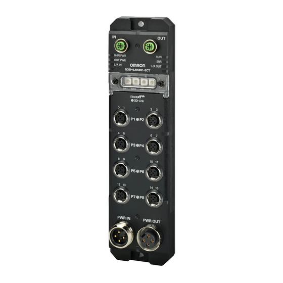
Omron NXR-ILM08C-ECT IO-Link Master Manuals
Manuals and User Guides for Omron NXR-ILM08C-ECT IO-Link Master. We have
2
Omron NXR-ILM08C-ECT IO-Link Master manuals available for free PDF download: User Manual, Manual
Omron NXR-ILM08C-ECT User Manual (354 pages)
Environment-resistive Remote Terminal
Brand:
Omron
| Category:
Touch terminals
| Size: 25 MB
Table of Contents
Intended Audience
3
Applicable Products
3
Manual Structure
4
Page Structure
4
Special Information
5
Precaution on Terminology
5
Sections in this Manual
7
Table of Contents
8
Terms and Conditions Agreement
14
Warranty, Limitations of Liability
14
Application Considerations
15
Disclaimers
15
Statement of Security Responsibilities for Assumed Use Cases and against Threats
16
Safety Precautions
17
Definition of Precautionary Information
17
Symbols
17
Warnings
18
Cautions
21
Precautions for Safe Use
22
Precautions for Correct Use
26
Regulations and Standards
27
Conformance to EMC and Electrical Safety Laws and Regulations
27
Conformance to UL and CSA Standards
28
Conformance to Shipbuilding Standards
28
Conformance to KC Certification
28
Unit Versions
29
Unit Versions and Support Software Versions
29
Related Manuals
30
Terminology
31
Revision History
34
Features and System Configuration
35
Introduction to the IO-Link Master Unit
36
Introduction to IO-Link
37
Functions of Port Pins and Connected External Devices
37
Introduction to Ethercat
39
How Ethercat Works
39
Types of Ethercat Communications
40
Features of the IO-Link Master Unit
42
Features as an Ethercat Slave
42
Features as an IO-Link Master
42
System Configuration
45
Support Software
47
Functions of the IO-Link Master Unit
48
Specifications
50
General Specifications
50
Ethercat Communications Specifications
50
Unit Specifications
51
Application Procedures
54
Parts and Names
58
Indicators
60
Status Indicators
60
I/O Indicators
62
Rotary Switches
65
ID Switch
65
SET Switch
66
Connectors
67
Ethercat Communications Connectors
67
Power Supply Connectors
67
I/O Connectors
68
Designing the Power Supply System
71
Power Supply Types and Power Supply System
72
Power Supply Types and Applications
72
Power Supply System
72
Designing the Power Supply System
77
Procedure for Designing the Power Supply System
77
Design Method for Direct Power Supply
77
Design Method for Power Supply System with Through-Wiring
83
Design Method for Power Supply System with Through-Wiring
90
Selecting Power Supplies and Protective Devices
90
Selecting External Power Supplies
90
Selecting Protective Devices
90
Installation and Wiring
93
Installing Units
94
Installation Precautions
94
Installation Orientations
94
Installation Method
94
Ethercat Network Wiring
96
Installation Standards
96
Installation Precautions
96
Preparing for Wiring
97
Connecting Communications Cables
97
Connecting the Power Supplies
102
Installation Precautions
102
Preparing for Wiring
102
Connecting Power Supply Cables to External Power Supplies
103
Connecting Power Supply Cables
104
Connecting I/O Cables
110
Installation Precautions
110
Preparing for Wiring
110
Wiring Examples
114
Precautions When Wiring External Output Signal Lines
121
Connected Devices
123
Ethercat Cables
123
Power Supply Cables
125
I/O Cables
125
Waterproof Covers for Connectors
127
Ethercat Communications
130
Structure of CAN Application Protocol over Ethercat (Coe)
130
Ethercat Slave Information Files (ESI Files)
131
Transitions of Communications States
131
Process Data Objects (Pdos)
132
Service Data Objects (Sdos)
135
Communications Mode
136
IO-Link Communications
137
Cyclic Communications for IO-Link Communications
137
Message Communications for IO-Link Communications
140
Setting up IO-Link Master Unit
141
Setting Items and Setting Procedures
142
Setting Items
142
Setting Procedures
143
Setting Device Parameters
144
List of Settings
144
Setting the Device Parameters of the IO-Link Master Unit
145
Setting PDO Mappings
146
Methods for Setting PDO Mappings
146
PDO Mapping Objects and PDO Entries that Can be Allocated
147
Details of PDO Entries
149
Configuring the Setting Parameters
161
Backing up and Restoring Device Parameters
162
I/O Refreshing
163
Introduction to I/O Refreshing
164
Communications Performance
166
I/O Response Time for IO-Link Devices
166
I/O Response Time for Non-IO-Link Connected External Devices
168
Functions
173
List of Functions
173
Sysmac Device Functionality
175
Error Notifications Based on the Sysmac Error Status
175
Saving Node Address Settings
175
Verifying the Ethercat Network Configuration Using Serial Numbers
176
SII Data Checking
176
Communications Mode Settings
177
Overview of Function
177
Details on Function
177
Automatic Baud Rate Setting for IO-Link Communications
179
Load Rejection During Communications Errors with Controller
180
Overview of Function
180
Details on Function
180
Digital Input Filter
182
Overview of Function
182
Details on Function
182
Digital Input Collection
185
Overview of Function
185
Details on Function
185
IO-Link Device Verification
188
Overview of Function
188
Details on Function
188
I/O Cable Short-Circuit Detection
192
Overview of Function
192
Details on Function
192
Monitoring Unit/Input Power Supply Voltage
194
Overview of Function
194
Details on Function
194
Monitoring Output Power Supply Voltage
196
Overview of Function
196
Details on Function
196
9-12 Monitoring Total Power-ON Time
198
Overview of Function
198
Details on Function
198
IO-Link Total Communications Lost Frames
199
Overview of Function
199
Details on Function
199
Backing up and Restoring IO-Link Device Parameters
202
Overview of Function
202
Backing up IO-Link Device Parameters
203
Restoring IO-Link Device Parameters
207
Settings
207
Executing a Start Command for Backup through SDO Communications
208
Clearing Backup Data
208
Recording Last-Connected Device Information
211
Overview of Function
211
Details on Function
211
IO-Link Communications Delay Time Settings
214
Overview of Function
214
Details on Function
214
9-17 I/O Port Quick Settings
217
Overview of Function
217
Details on Function
217
10-1 Methods for Setting IO-Link Devices
222
Setting IO-Link Devices with the CX-Configuratorfdt
223
Overview of the CX-Configuratorfdt
223
Flow of Operations for the CX-Configuratorfdt
224
Installing the CX-Configuratorfdt in Your Computer
225
Installing IODD Files for IO-Link Devices from Other Companies in the CX-Configuratorfdt.10-5
225
Installing IODD Files for IO-Link Devices from Other Companies in the CX-Configuratorfdt
225
Starting the CX-Configuratorfdt
226
Creating the Network Configuration
227
Setting the IO-Link Device Parameters
230
Exporting the Created Network Configuration to a File
230
Importing the Network Configuration from a File
231
10-2-10 Going Online
231
10-2-11 Precautions When Transferring All of IO-Link Device Settings
232
10-2-12 Transferring the IO-Link Device Parameters
233
Troubleshooting
237
11-1 Checking for Errors
238
How an Error Is Notified and What Information to Check
238
How to Check for Errors
240
Checking for Errors and Troubleshooting with the Indicators
242
Checking for Errors and Troubleshooting with the I/O Indicators
245
Checking for Errors with the Status in I/O Data
250
Checking for Errors in the IO-Link Master Unit
250
Checking for Errors in IO-Link Devices
250
Checking for Errors and Troubleshooting with the Troubleshooting Functions
251
Checking for Errors and Troubleshooting with the Troubleshoot- Ing Functions
251
How to Check for Errors
251
Number of Errors that Can be Checked
251
Error Table
252
Error Descriptions
256
Error Notification through Emergency Messages
263
What Is an Emergency Message
263
Emergency Message Detected Event
263
Contents of Emergency Messages
263
List of Emergency Error Codes
263
Emergency Message Error Log and How to Read It
265
Error Notifications Based on the al Status
266
11-7 Resetting Errors
268
Checking for Device Events and Troubleshooting IO-Link Devices
269
Troubleshooting with Device Events
269
Checking the Occurrence of Device Events
269
Checking for Device Events
270
Assumed Causes and Corrections for Other Errors
273
Inspection and Maintenance
275
12-1 Cleaning and Inspection
276
Cleaning
276
Inspection Procedure
276
12-2 Maintenance Procedures
278
Handling the Unit to Replace
278
Replacing the IO-Link Master Unit
278
Replacing IO-Link Devices
279
Replacing the IO-Link Master Unit and IO-Link Devices at the same Time
279
Appendices
281
A-1 Coe Objects
282
A-1-1 Object Dictionary Area
282
A-1-2 Data Types
282
Object Dictionary Area
282
Data Types
282
A-1-3 Format of Objects
283
A-1-4 Communication Objects
283
Format of Objects
283
A-1-5 PDO Mapping Objects
290
PDO Mapping Objects
290
A-1-6 Sync Manager Communications Objects
296
Sync Manager Communications Objects
296
Manufacturer-Specific Object 1
300
Manufacturer-Specific Object 2
303
Manufacturer-Specific Object 3
316
A-1-10 Manufacturer-Specific Object 4
318
A-1-11 Device Profile Area
324
System Configuration for Controllers from Another Company
326
A-2-1 System Configuration
326
System Configuration
326
A-2-2 Basic Application Procedure
327
Basic Application Procedure
327
A-3 Sample Programming
330
A-3-1 I/O Data Communications with Valid I/O Data
330
I/O Data Communications with Valid I/O Data
330
Configuring the IO-Link Master Unit through Message Communications
332
Configuring IO-Link Devices through Message Communications
332
A-4 IO-Link Master Simple Settings
339
Setting IO-Link Master Parameters and Editing the I/O Data Size in the IO-Link Master Simple Settings Tab Page
340
A-4-2 Generating the Process Data Structure of the IO-Link Device
342
Generating the Process Data Structure of the IO-Link Device
342
Example of Allocating Variables to the I/O Ports
343
A-5-1 Checking the Status of the IO-Link Master Unit
343
A-5-2 IO-Link Process Input Data from E3Z Photoelectric Sensors, and I/O Map
343
A-5-3 IO-Link Process Input Data from E3S Color Mark Sensors, and I/O Map
344
A-6 Dimensions
347
A-7 Version Information
348
Advertisement
Omron NXR-ILM08C-ECT Manual (25 pages)
Environment-resistive Remote Terminal NXR-series IO-Link Master Unit for EtherCAT
Brand:
Omron
| Category:
Touch terminals
| Size: 5 MB
Table of Contents
System Configuration
2
Ordering Information
5
General Specifications
9
Ethercat Communications Specifications
10
Unit Specifications
11
Version Information
13
External Interface
14
Power Supply System
20
Related Manuals
22
Terms and Conditions Agreement
23
Advertisement
Related Products
Omron NXR-ILM08C-EIT
OMRON NS8-TV Series
OMRON NSH5-SQG10B-V2 - 10-2010
Omron NB3Q-TW00B
Omron NA5-9W series
Omron NS8-TV10 V1 Series
Omron NS5-SQ00 V2 Series
Omron NS5-MQ00 V2 Series
Omron NS15-TX01S-V2
Omron NT631 Series
Omron Categories
Blood Pressure Monitor
Controller
Accessories
Switch
Inverter
More Omron Manuals
Login
Sign In
OR
Sign in with Facebook
Sign in with Google
Upload manual
Upload from disk
Upload from URL