
Subscribe to Our Youtube Channel
Related Manuals for Tadiran Telecom aeonix TGW4


Summary of Contents for Tadiran Telecom aeonix TGW4
- Page 1 TGW SIP-FXS/FXO Gateway Series User Guide TGW4 Models TGW8 Models TGW16/24 Models TGW96 Models D o c u m e n t E d itio n 1 .1...
- Page 2 If you have encountered an error, please notify the Manufacturer. All specifications are subject to change without prior notice. © Copyright by TADIRAN TELECOM (TTL) L.P., 2015-2018. All rights reserved worldwide. All trademarks contained herein are the property of their respective holders.
- Page 3 Record of Changes Edition Issue Brief Description Date 1 .1 J a n -1 6 -2 0 1 8 M in o r e d its a n d fo rm a tin g 1 .0 J u n -8 -2 0 1 7 E d itio n , u p d a te s 3 4 4 a n d 3 5 1 New Rock Technologies, Inc.
-
Page 4: Table Of Contents
2.1.5 SSH user Permissions ..............................26 2.2 Basic Configuration .................................. 26 2.2.1 Status ....................................26 2.2.2 Network ..................................26 2.2.3 VLAN ....................................29 2.2.4 System ..................................... 30 2.2.5 SIP ..................................... 32 2.2.6 High Availability ................................34 2.2.7 TLS&SRTP ..................................35 Tadiran Telecom... - Page 5 2.7.1 Access Security ................................79 2.7.2 Access list ..................................81 2.7.3 Brute Force Login Prevention ..........................83 2.7.4 ACL-based Traffic Filtering ............................84 2.7.5 Packet Rate Limiting Based Dynamic Blacklisting ................... 85 2.7.6 IP Table ................................... 88 2.7.7 Voice Security ................................88 Tadiran Telecom...
- Page 6 4 Making an OpenVPN Client Certification (TGW4/ TGW8) ............115 5 Appendix: High availability configuration ..................118 5.1 Function Definition ................................118 5.2 Server Cluster ..................................119 5.3 Configuring Primary-Standby Mode ..........................119 5.4 Configuring Active-Standby Mode ..........................121 Tadiran Telecom...
- Page 7 5.5 Configuring Load Balancing Mode ..........................123 6 Appendix: Auto provisioning configuration ................. 125 Tadiran Telecom...
-
Page 8: Figures
Figure 2-5 VLAN Configuration Interface ..........................29 Figure 2-6 System Configuration Interface ..........................31 Figure 2-7 SIP Configuration Interface ............................ 33 Figure 2-8 High Availability Configuration Interface ......................34 Figure 2-9 TLS&SRTP Configuration Interface ........................35 Figure 2-10 MGCP Configuration Interface ........................... 36 viii Tadiran Telecom... - Page 9 Figure 2-42 Static Defense Configuration Interface ......................84 Figure 2-43 Dynamic Defense Configuration Interface ..................... 86 Figure 2-44 Dynamic Defense (Blocked IP Addresses) Interface..................87 Figure 2-45 IP Table Configuration Interface ........................88 Figure 2-46 Voice Security Configuration Interface ......................89 Tadiran Telecom...
- Page 10 Figure 3-79 Network Environment ............................112 Figure 3-80 Configuring Multi-Service VLAN ........................113 Figure 3-81 IP Addresses of the Device in Multi-Service VLAN................... 113 Figure 3-82 SIP Data Packet Carrying VLAN Tag of the Voice VLAN in the Multi-Service VLAN Mode ..114 Tadiran Telecom...
- Page 11 Figure 5-86 Primary-Standby configuration page ......................120 Figure 5-87 DNS server configuration page ........................120 Figure 5-88 Active-Standby configuration page ....................... 122 Figure 5-89 Page to disable PSTN failover .......................... 123 Figure 5-90 Load balancing configuration page ....................... 124 Tadiran Telecom...
- Page 12 Table 1-27 Meanings of TGW96 Indicators ........................... 18 Table 1-28 TGW96 System Operation State .......................... 18 Table 1-29 TGW96-2G Interface Card ............................18 Table 1-30 Configuration Combination of TGW96-2G ...................... 19 Table 1-31 Description of TGW96-2G Front Panel ......................19 Tadiran Telecom...
- Page 13 Table 2-27 Media Stream Configuration Parameter ......................67 Table 2-28 SIP Related Configuration Parameter ........................ 69 Table 2-29 RADIUS Configuration Parameter ........................72 Table 2-30 Greeting Configuration Parameters ........................73 Table 2-31 Call Progress Tone Configuration Parameters ....................73 Tadiran Telecom xiii...
- Page 14 Table 2-40 Subsequent choices for moving the Blocked IP Addresses to static defense ........87 Table 2-41 Encryption Configuration Parameters ....................... 89 Table 2-42 VPN Configuration Parameters ..........................91 Table 2-43 System Status Parameters ............................94 Table 2-44 Log Management Configuration Parameters ....................96 Tadiran Telecom...
- Page 15 Tadiran Telecom...
-
Page 17: Overview
1U High TGW24-16-2G TGW24-16-2G-DC (Optional) TGW24-2G-16S/16B TGW24-24-2G TGW24-24-2G-DC TGW16-3G 16 - 48 19-inch Rack TI A8, 128MB 32MB 100-240 TGW16-3G-DC wide and VAC, -36 to 1GHz TGW24-16-3G 1U High -72 VDC TGW24-16-3G-DC (optional) TGW24-3G-16S/16B Dual power TGW24-24-3G (optional) TGW24-24-3G-DC Tadiran Telecom... -
Page 18: Functions And Features
SIP registrar server. Flexible configuration of subscriber/trunk interfaces Support G.711, G.729 Support echo cancellation Up to 500 routing rules can be stored in gateways Intercom Support concurrent calls under full load Tadiran Telecom... -
Page 19: Equipment Structure
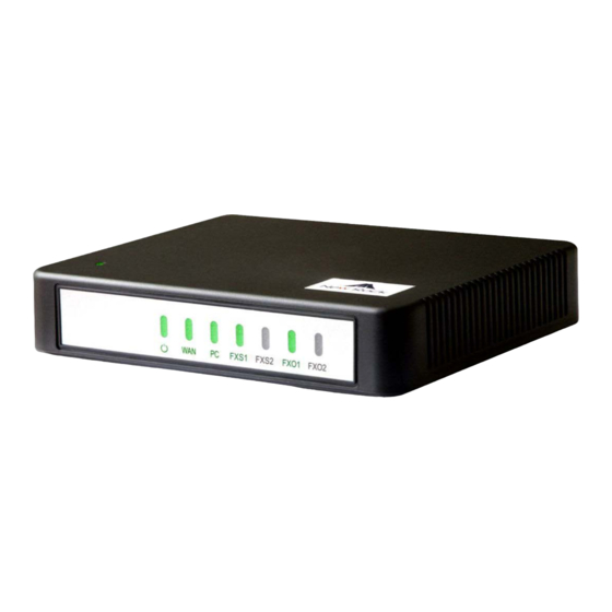
The TGW4 adopts a compact plastic structural design and can be placed on a desk. It provides either two or four FXS/FXO ports. The TGW4 supports the following models. Table 1-2 Configuration Combinations of TGW4 Models Number of FXS Ports Number of FXO Ports TGW4S Tadiran Telecom... -
Page 20: Figure 1-1 Tgw4 Front Panel
DHCP. If no IP address is obtained, 192.168.2.218 is used by default, and you can change it on Basic > Network page. FXO/FXS FXS port or FXO port Table 1-5 Indicator Status of TGW4 Indicator Status Description PWR(green) Blinking green The device is starting. Tadiran Telecom... -
Page 21: Tgw8-2G
The TGW8-2G adopts a compact metal structural design. It can be placed on a desk or installed in a standard communications cabinet and provides eight analog ports. TGW8-2G supports the following types of configuration. Table 1-6 Configuration Combination of TGW8-2G Models Number of FXS Ports Number of FXO Ports TGW8-2G TGW8S-2G TGW8FXO-2G Tadiran Telecom... -
Page 22: Figure 1-3 Tgw8-2G Front Panel
Both are 10/100 Mbps Ethernet ports (RJ45). They share one IP address, which, by default, is obtained through DHCP. If no IP address is obtained, 192.168.2.218 is used by default, and you can change it on Basic > Network page. FXO/FXS FXS port or FXO port Tadiran Telecom... -
Page 23: Figure 1-5 Rj45 To Rs232 Serial Cable
The device is starting and the port is an FXO port. (Green-FXS, Blinking green The device is starting and the port is an FXS port. yellow-FXO) No line is detected. Possibly the voice interface card is not inserted or Tadiran Telecom... -
Page 24: Tgw16/24-2G
CAT-5 cables supplied with the unit. TGW16/24-2G offers up to 48 interfaces of FXS/FXO. TGW16/24-2G supports the following types of configuration. Table 1-10 Configuration Combinations of TGW16/24-2G Models Number of FXS Ports Number of FXO Ports TGW16-2G TGW16-2G-DC TGW24-16-2G TGW24-16-2G-DC TGW24-24-2G TGW24-24-2G-DC TGW-24-2G-16S/16B Tadiran Telecom... -
Page 25: Figure 1-7 Tgw16-2G Front Panel
RJ45 Socket Port Table 1-12 TGW16/24-2G RJ45 Pin Number Pair Pair Pair Pair Pair Analog line pair TIP1 RING1 TIP2 TIP3 RING3 RING2 TIP4 RING4 Orange Green Blue Brown Reference color Orange Blue Green Brown white white white white Tadiran Telecom... -
Page 26: Figure 1-8 Schematic Diagram Of Tgw16/24-2G Subscriber Line Connection
Configuration interface (CON), Ethernet lines used for local management and debugging ETH1/ETH2 Two 10/100 Mbps Ethernet ports (RJ45). They share one IP address, which by default is 192.168.2.240, and you can change it on Basic > Network page. Cooling fan AC power socket, 100-240 VAC voltage input. Tadiran Telecom... -
Page 27: Tgw16/24-3G
CAT-5 cables. TGW16/24-3G offers up to 48 analog line ports and supports the following configurations: Configuration Combinations of TGW16/24-3G Table 1-15 Models Number of FXS Ports Number of FXO Ports TGW16-3G TGW16-3G-DC TGW24-16-3G TGW24-16-3G-DC TGW24-24-3G TGW24-24-3G-DC TGW-24-3G-16S/16B Tadiran Telecom... -
Page 28: Figure 1-11 Tgw16-3G Front Panel
Pin Specifications for TGW16/24-3G RJ45 Socket Port Table 1-17 RJ45 Pin Number Pair Pair Pair Pair Pair Analog line pair TIP1 RING1 TIP2 TIP3 RING3 RING2 TIP4 RING4 Orange Green Blue Brown Reference color Orange Blue Green Brown white white white white Tadiran Telecom... -
Page 29: Figure 1-12 Schematic Diagram Of Tgw16/24-3G Subscriber Line Connection
Configuration interface (CON), used for local management and debugging ETH1/ETH2 Two 10/100 Mbps Ethernet ports (RJ45). They share one IP address, which by default is 192.168.2.240, and you can change it on Basic > Network page. AC power socket, 100-240 VAC voltage input. Tadiran Telecom... -
Page 30: Tgw96
C o n c u rre n t c a lls M o d e ls N u m b e r o f F X O P o rts P o rts TGW96-24-C TGW96-24-2AC-C Depend on the models and number of the interface cards. TGW96-24-2DC-C Tadiran Telecom... -
Page 31: Figure 1-14 Tgw96 Front Panel
R J 4 5 P in N u m b e r Pair Pair Pair Pair Pair Analog line pair TIP1 RING1 TIP2 TIP3 RING3 RING2 TIP4 RING4 Reference color Orange Blue Green Brown Orange Green Blue Brown Tadiran Telecom... -
Page 32: Figure 1-15 Schematic Diagram Of Tgw96 Subscriber Line Connection
Usually, this mode is entered when some prompts are required to give operator during equipment startup, diagnosis or operation. In this mode, LED flashes to display numbers, letters or other patterns in matrix. Please refer to Table 1-28. Tadiran Telecom... -
Page 33: Figure 1-16 Tgw96 Back Panel-Ac
Two 10/100 Mbps Ethernet ports (RJ45). They share one IP address, which by default is 192.168.2.240 and you can change it on Basic > Network page. Cooling fan AC power socket, 100-240 VAC voltage input. DC power socket, -48 VDC input. Tadiran Telecom... -
Page 34: Tgw96-2G
The device of TGW96-2G can hold four interface cards to flexibly configure FXS and FXO ports, and each card equips 24 ports. TGW96-2G can provide up to 96 ports. It supports the following configurations: Table 1-29 TGW96-2G Interface Card Type FXS Ports FXO Ports 24FXS 24FXO 16FXS/8 12FXS/12 Tadiran Telecom... -
Page 35: Figure 1-18 Tgw96-2G Front Panel
CAT-5 cables are used to connect the interface card and distribution panel in equipment installation. Standard RJ11 telephone lines can be used to plug in a RJ45 socket. The telephone/trunk lines are connected to the 3 pair of pins for simple call test. Tadiran Telecom... -
Page 36: Figure 1-19 Schematic Diagram Of Tgw96-2G Subscriber Line Connection
Ethernet cables (Both WAN and LAN ports must be disconnected) at installation stage. After entering this mode, steady on LED indicates that the corresponding line is equipped as analog subscriber line type, b LED indicates that the linking Tadiran Telecom... -
Page 37: Figure 1-20 Tgw96-2G Back Panel-Ac
Two 10/100 Mbps Ethernet ports (RJ45). They share one IP address, which by default is 192.168.2.240 and you can change it on Basic > Network page. USB interface AC power socket, 100-240 VAC voltage input. DC power socket,-48 VDC input. Ground Pole Tadiran Telecom... -
Page 38: Table 1-35 Meanings Of Tgw96-2G Indicators
Blinking with C IP address conflicts Blinking with D The severe starting failure needs to address by your dealer Blinking with E Network failure Blinking with P Software upgrading Blinking with T App exited (The device cannot be used normally) Tadiran Telecom... -
Page 39: Parameters Setting
192.168.2.218, set the computer’s IP address to any address at the network segment of 192.168.2.XXX. 2.1.2 Logging On to Web GUI Enter the gateway IP address and verification code (case-insensitive) in the browser address bar (e.g. 192.168.2.218). You can enter the gateway configuration login interface by entering a password on the Tadiran Telecom... -
Page 40: Gateway Administrator And Operator Rights (Web Gui)
The password is shown in a cipher for safety. Table 2-2 Default Passwords for logging to Web GUI Type Default Administrator Passwords Default Operator Password (lowercase letters required) TGW8-2G voip operator TGW4 voip operator TGW16/24-2G operator voip TGW16/24-3G voip operator TGW96 operator voip TGW96-2G operator voip Tadiran Telecom... -
Page 41: Accessing Through Ssh
Step 3 Run su root to switch to the root user. Enter the password (voipgateway by default) of the root user. Disable SSH in time after use. To change the SSH access port, go to Security > Access page. For details, see 2.7.1 Access Security. Tadiran Telecom... -
Page 42: Ssh User Permissions
After login, open the Basic tab page to view device information. If the SIP port of the device is 5060, you are advised to modify it. Figure 2-2 Status Interface 2.2.2 Network After login, click Basic>Network to open the configuration interface. Tadiran Telecom... -
Page 43: Figure 2-3 Network Configuration Interface (Tgw4/Tgw8)
Methods for obtaining an IP address. Static IP address: static IP address is used; Obtain an IP address automatically: use the dynamic host configuration protocol (DHCP) to obtain IP addresses and other network parameters; PPPoE: PPPoE service is used. Tadiran Telecom... - Page 44 IP address of the device by using STUN query. The IP address obtained through STUN is used in SIP message fields such as Via and Contact and SDP C field. Tadiran Telecom...
-
Page 45: Vlan
The value range is 5 to 3600 seconds. The default value is 30 seconds. DHCP Enable the device to obtain the VLAN tag and QoS by using DHCP option 132 and option 133. Note: This function works only when DHCP is selected on Basic>Network page. Manual configuration Activate Enable/disable VLAN. Tadiran Telecom... -
Page 46: System
FXS port of the device, and dialing ##. In the case of a single VLAN, the IP address of the single VLAN is voiced; in the case of a multi-service VLAN, the IP address of the management VLAN is voiced. 2.2.4 System After login, click Basic>System to open the configuration interface. Tadiran Telecom... -
Page 47: Figure 2-6 System Configuration Interface
The gateways provide the following processing modes after detecting hook flash from subscriber terminals: Internal: the hook flash event will be handled internally; Server(RFC 2833): transmitting the hook flash to platform with RFC 2833; Server (SIP INFO): transmitting the flash-off to platform with SIP INFO. Tadiran Telecom... -
Page 48: Sip
TGW4,TGW8, TGW16/24-2G, G.711U/G.711A 10/20 (default value)/30/40 TGW16/24-3G, TGW96-2G TGW16/24-2G, TGW16/24-3G, G.723 5.3/6.3 30 (default value)/60 TGW96-2G TGW16/24-2G, TGW16/24-3G, iLBC 13.3/15.2 20/30 (default value) TGW96-2G TGW16/24-2G, TGW16/24-3G, TGW96-2G 2.2.5 SIP After login, click Basic>SIP to open the configuration interface. Tadiran Telecom... -
Page 49: Figure 2-7 Sip Configuration Interface
When a domain name is used, you can fill in a backup IP address in Backup SIP proxy server in the High Availability configuration. This allows the device to failover to the IP address if the domain name resolution service fails. Tadiran Telecom... -
Page 50: High Availability
After login, click Basic>SIP to open the configuration interface. For details, see Appendix XXX. Figure 2-8 High Availability Configuration Interface Table 2-8 Parameters Name Description Mode High availability can be configured as Primary-Standby, Active-Standby or Load Balancing mode. Primary-Standby mode Tadiran Telecom... -
Page 51: Tls&Srtp
2.2.7 TLS&SRTP The TGW series gateways support SIP signaling over TLS and SRTP (an encrypted form of RTP) as well. . After login, choose Basic > SIP, to go to the configuration page. Figure 2-9 TLS&SRTP Configuration Interface Tadiran Telecom... -
Page 52: Mgcp (Not Relevant For Operation Under Aeonix)
The gateways use SIP protocol by default. When the gateways need to interface with MGCP protocol -based softswitch platform, set the relevant parameters here. After login, click Basic > MGCP to open the configuration interface. Figure 2-10 MGCP Configuration Interface Tadiran Telecom... -
Page 53: Table 2-10 Mgcp Configuration Parameters
Selected: the gateways will report timeout in terms of its own timeout setting (the time interval set in non-dial timeout of configuration system parameters) when subscribers has not dialed up in time after offhook. Using configured digit map Select whether to activate the digit map configured by local gateway. Default not selected. Tadiran Telecom... -
Page 54: Foip
Default not selected. Keep connection when Select if the gateways actively cancel connection disconnect when subscribers hook on. on-hook Default not selected. 2.2.9 FoIP After login, click Basic>FoIP to open this interface. TGW4/TGW8 Fax Configuration Interface ( Figure 2-11 Tadiran Telecom... -
Page 55: Figure 2-12 Tgw16/24-2G, Tgw16/24-3G, Tgw96-2G Fax Configuration Interface
Enable G.711 pass-through according to the your device model: TGW4/TGW8: Select G.711 pass-through in this area. TGW16/24, TGW16/24-2G, TGW96-2G: Select G.711 in this field, and then select Pass-through. Adjustable parameters when G.711 pass-through is enabled (default values are recommended): Tadiran Telecom... -
Page 56: Alarm
The device provides the following alarm types based on the severity: Table 2-12 Alarm Type Type Severity Description Indicates that a service-affecting or severe security condition has occurred that Red alarm Critical requires corrective action as soon as possible. Tadiran Telecom... -
Page 57: Figure 2-13 Alarm Icon
Alarm Icon Figure 2-14 Alarms Interface You may do the following operations: History: Click to download the security event log. Acknowledge: Click to acknowledge the alarm. Acknowledge All: Click to acknowledge all alarms of this type. Tadiran Telecom... -
Page 58: Line
Fill in the telephone number associated with the subscriber line n (FXS port). This should be manually performed if Batch mode is not used. 2.3.2 Subscriber Line Features The content below is only applicable to gateways with FXS ports. After login, click Line > Configuration to open the configuration interface. Tadiran Telecom... -
Page 59: Figure 2-16 Subscriber Line Configuration Interface
If Registration is selected, you should enter the user name for registering the line here. This is not mandatory. If this parameter remains blank, the phone number of the extension set is used. Registrar If Registration is selected, users must enter the authentication password for registering of this line password here. Tadiran Telecom... - Page 60 P-Asserted-Id field preferentially: The caller identification information is preferentially obtained from the P-Asserted-Id field in the INVITE message. From field only: The caller identification information is obtained from the From field in the INVITE message. From field only is selected by default. Tadiran Telecom...
-
Page 61: Subscriber Line Batch (Unavailable On The Tgw4)
After login, click Line> Batch to open the configuration interface. Step 1 Click , the following interface is shown. Choose batch configured features and click OK. Step 2 Click to activate this function to configure this parameter. For details of the parameter, see Line > Configuration. Tadiran Telecom... -
Page 62: Subscriber Line Characteristics
T G W S IP -F X S /F S O G a te w a y S e rie s Feature Batch Configuration Interface Figure 2-17 2.3.4 Subscriber Line Characteristics The content below is only applicable to gateways with FXS ports. After login, click Line > feature to open the configuration interface. Tadiran Telecom... -
Page 63: Figure 2-18 Subscriber Line Characteristics Configuration Interface
Used by the gateway to detect Hook Flash event, the default is 75 milliseconds. The gateway will ignore any flash that fall short of the shortest flash time. Generally, this value should not be less than 75 milliseconds. Tadiran Telecom... - Page 64 Set the parameter Alert-Infon according to the “Alert-Info” value provided on the SIP server. Distinctive Alert/Ringing When the “Alert-info” value of received INVITE message matches with the Alert-Infon, ring cadence n is activated. Alert-Info 1 Match with ring cadence 1. Tadiran Telecom...
-
Page 65: Trunk
Line 2 increases 1 progressively based on that of Line 1, and so on. ID n Fill in the telephone number associated with the trunk n (FXO port). This should be manually performed if Batch mode is not used. Tadiran Telecom... -
Page 66: Trunk Features
Note: This parameter is displayed only when Multi port is checked on Advanced>SIP page. Registration Select if this trunk registers with the SIP registration server. By default, this is not selected. Password If Registration is selected, the authentication password for registering this line must be entered here. Tadiran Telecom... -
Page 67: Trunk Batch (Unavailable On The Tgw4)
After login, click Trunk >Batch to open the configuration interface. Step 1 Click , the following interface is shown. Choose batch configured trunks and click OK. Step 2 Click to activate this function to configure this parameter. For details of the parameter, see Trunk > Feature. Tadiran Telecom... -
Page 68: Trunk Characteristics
T G W S IP -F X S /F S O G a te w a y S e rie s Trunk Batch Configuration Interface Figure 2-21 2.4.4 Trunk Characteristics Only a gateway with FXO ports can display this interface. After login, click Trunk > Advanced to open the configuration interface. Tadiran Telecom... -
Page 69: Figure 2-22 Trunk Characteristics Configuration Interface
PSTN. The default is 600 in milliseconds. Note: This parameter is used to match the digit receiving response time of the PSTN PBX. Call ID detection Before ringing; After ringing. The After ringing mode is generally used. Tadiran Telecom... -
Page 70: Routing
Busy tone frequency If Detect dual-frequency busy tones is enabled, you need to specify the frequency to be detected. Unit: Hz. Routing 2.5.1 Digit Map After login, click Routing>Digit Map to open the dialing rules interface. Tadiran Telecom... -
Page 71: Figure 2-23 Configuration Interface For Digit Map
# key. Terminate after receiving * and any two-digit number. *xx is primarily used to activate feature codes for supplementary services, such as CRBT, Call Transfer, Do not Disturb, etc. Tadiran Telecom... -
Page 72: Routing Table
Dial rules by default are as follows: 01[3-5,7,8]xxxxxxxxx 010xxxxxxxx 02xxxxxxxxx 0[3-9]xxxxxxxxxx 11[0,2-9] 111xx 123xx 95105xxx 95xxx 100xx 1[3-5,7,8]xxxxxxxxx [2-3,5-7]xxxxxxx 8[1-9]xxxxxx 80[1-9]xxxxx 800xxxxxxx 4[1-9]xxxxxx 40[1-9]xxxxx 400xxxxxxx xxxxxxxxxx.T 2.5.2 Routing Table After login, click Routing > Routing Table to open the configuration interface. Tadiran Telecom... -
Page 73: Figure 2-24 Routing Table Configuration Interface
8000 or 8001 are routed to FXO port in a sequential order. Namely, FXO Port 2 is selected when FXO Port 1 is busy and so on. Where IP is the source, 800[0-1] is the number, and FXO 1-2 is the routing destination. Tadiran Telecom... -
Page 74: Table 2-20 Routing Table Format
Add 8888 at the end of the calling number starting with 6120 for calls from an FXS (Phone/fax) port. REPLACE Number replacement. The replacing number follows REPLACE. Example: FXS CPN88 REPLACE 2682000 Replace the calling number beginning with 88 for calls from FXS port with 2682000. Tadiran Telecom... -
Page 75: Table 2-22 Routing Destination
Calling barring (also known as “blacklist”). Example: IP CPN[1,3-5] ROUTE NONE Bar all calls from IP, of which the calling numbers start with 1, 3, 4, and 5. Block all calls from IP numbers starting with 1, 3, 4, 5 Tadiran Telecom... -
Page 76: Examples Of Routing Rules
Here is an example of terminating incoming calls from analog trunks to a hunt group consisting of ports FXS1 and FXS2 in round-robin fashion: ROUTE 1-2/R Outbound Call Barring Restrict users to make certain calls, such as an international call. Examples are as follows: Tadiran Telecom... -
Page 77: Advanced Configuration
FXO1 to FXO4 in sequential fashion: ROUTE Further, we set up the trunk group such that it is used only by calls to destinations with prefix 6120: 6120 ROUTE Advanced Configuration 2.6.1 System After login, click Advanced > System to open this interface. Tadiran Telecom... -
Page 78: Figure 2-25 Interface Of System Advanced Configuration
Remote recording Call recordings are stored on an external Windows or Linux based recording server, on which the agent provided by Tadiran Telecom collects and stores the call recording files. Set this parameter to the IP address of the server. -
Page 79: Auto Provisioning
Note: If the ACS is a TFTP server, the username and the password are not displayed. Password Input a password for accessing the ACS. Firmware upgrade Supports firmware download and update using ACS. Note: The firmware can be a tar.gz file or an img file. Tadiran Telecom... -
Page 80: Management System Type
If SNMP is selected, the following three parameters need to be specified. Server Enter the address of the SNMP server. Trap port Enter the port number of the SNMP server. The default value is 162. Notification interval The default value is 900 seconds. Tadiran Telecom... -
Page 81: Certificate (Available On The Tgw4/Tgw8)
The account used for the ACS to connect back to the device, for example, admin. username Connection request The password used for the network management server to connect back to the device. password 2.6.4 Certificate (Available on the TGW4/TGW8) After login, click Advanced >Cert. to open the interface. Tadiran Telecom... -
Page 82: Media Stream
Step 2 Click Upload. Step 3 Select and upload the file client.ovpn. Step 4 Reboot the device. 2.6.5 Media Stream After login, click Advanced > Media Stream to open this interface. TGW4/TGW8 Figure 2-30 Media Stream Configuration Interface Tadiran Telecom... -
Page 83: Figure 2-31 Tgw16/24-2G, Tgw16/24-3G, Tgw96-2G Media Stream Configuration Interface
Select to discard received RTP SID voice packets. By default, SID voice packets will not be dropped. Note: RTP SID packets should be dropped only when they are in nonconformity to the specifications. Nonstandard RTP SID data could generate noise for calls. Tadiran Telecom... -
Page 84: Sip Configuration
Parameter line: Via, From, To, Contact, Csq, Content-length, Max-forward, Content-type, White Space, and SDP etc. TGW gateways provide flexibility in field setting in order to improve compatibility with the SIP register server. After login, click Advanced > SIP to open this interface. SIP Related Configuration Interface Figure 2-32 Tadiran Telecom... -
Page 85: Table 2-28 Sip Related Configuration Parameter
Contact field in Select either the External network IP address or the LAN IP address. REGISTER External network IP address: use the NAT information returned by registration server. LAN IP address: keep original content of Contact when register. Tadiran Telecom... - Page 86 INVITE request retransmit interval, for UDP only. It is 1000 ms by default. Timer B INVITE transaction timeout timer. It is 16000 ms by default. Timer D Wait time for response retransmits. It is 16000 ms by default. Tadiran Telecom...
-
Page 87: Radius (Unavailable On The Tgw4, Not Relevant For Operation Under Aeonix))
Specify the local port used by SIP/TCP. Local TCP port 2.6.7 RADIUS (Unavailable on the TGW4, not relevant for operation under Aeonix)) After login, click Advanced >RADIUS to open this interface. Figure 2-33 RADIUS Configuration Interface Tadiran Telecom... -
Page 88: Greeting
Set whether to send RADIUS charge message for Outbound calls Inbound calls When calls are connected Unanswered calls 2.6.8 Greeting After login, click Advanced>Greeting to open the audio files interface. Figure 2-34 Greeting Interface Tadiran Telecom... -
Page 89: Call Progress Tone Plan
User-defined: define the call progress tones by yourself. Dial tone Prompt tone of off-hook dial tone. Second dial tone Second stage dial tone. Stutter dial tone Prompt of voice mail, or when the subscriber line is set with “Do not Disturb Service and Call Transfer”. Tadiran Telecom... -
Page 90: Feature Access Codes
Using #xx (dial # and 2 digits number) to cancel a service. This is illustrated with the following defaults for various parameters, which may be modified according to requirements. It is highly recommended not to modify the default configuration in System feature codes. Tadiran Telecom... -
Page 91: Figure 2-36 Feature Codes Configuration Interface
(See 2.3.2 Subscriber Line Features). Deactivate CFB The feature code for deactivating call forwarding on busy, with default of #61. User operation: off hook → press #61 → hang up. Tadiran Telecom... -
Page 92: Clock Service
User operation: off hook → press *88 → input color ring number. While listening, you can press a two-digit CRBT index to change to another CRBT file. Three-way calling The default value is *79. 2.6.11 Clock Service After login, click Advanced > System time to open this interface. Tadiran Telecom... -
Page 93: Figure 2-37 Clock Service Interface
User Manual T G W S IP -F X S /F S O G a te w a y S e rie s Clock Service Interface Figure 2-37 Tadiran Telecom... -
Page 94: Table 2-33 Clock Service Parameters
Display current time for the device. Click Clock calibration to calibrate the time. System time sync Set the synchronization period of the time. It is 120 minutes by default. interval Primary time server Enter the IP address of preferred time server here. It has no default value. Tadiran Telecom... -
Page 95: Security
Regularly change the root/operator password for accessing the device through SSH, and improve the password strength Regularly change the HTTP/HTTPS/SSH port for accessing the device Disable SSH once accessing is completed. All of the above are available on Security>Access page. Tadiran Telecom... -
Page 96: Figure 2-38 Access Configuration Interface
HTTP/HTTPS port is use for: Web accessing (XML command interface) Auto Provisioning Login time out Set the login timeout interval, the default value is 600s. If you do not conduct any operation within timeout interval, you will log out. Tadiran Telecom... -
Page 97: Access List
After login, click Security>Access list to open the configuration interface. Once access list is enabled, only addresses specified here are allowed to access the device through Web GUI or SSH. Access list configuration Interface Figure 2-39 Step 1 Click Add. Tadiran Telecom... - Page 98 Step 2 In the input box, enter IP addresses and select types of service. Step 3 Select Enable, and click Save. If SSH is selected, please enable SSH on Security>Access page. The device allows an access list of up to 20 entries. Tadiran Telecom...
-
Page 99: Brute Force Login Prevention
Value range: 1–5 times/day Default value: 3 times/day Lock time Specify the IP address lock time. An IP address will be unlocked after the lock time and is allowed to access the device again. Default value: 10 minutes Locked IP addresses Tadiran Telecom... -
Page 100: Acl-Based Traffic Filtering
Specify whether to receive or block data packets when the specified conditions are matched (source IP address, local port, protocol). Local port Specify the local port range of the device for receiving data packets. Range is 0 to 65535. Tadiran Telecom... -
Page 101: Packet Rate Limiting Based Dynamic Blacklisting
IP address of the attack source is added to the blocked list. Data packets from this address will no longer be received. Rule configuration After login, choose Security > Dynamic defense, to go to the configuration interface. Tadiran Telecom... -
Page 102: Figure 2-43 Dynamic Defense Configuration Interface
: Duplicate the selected rule to a new rule Delete : Delete the selected rule Batch delete: Batch Delete all selected rules Blocked IP addresses The blocked IP addresses of dynamic defense will be deleted after the device reboots. Tadiran Telecom... -
Page 103: Figure 2-44 Dynamic Defense (Blocked Ip Addresses) Interface
Cancel to add the entry to the static defense list. Cancel ACL-based Traffic Filtering For details about static defense, see 2.7.4 Batch delete: Delete selected entries in a batch. Example Explanations of the rules listed in Figure 2-43 are as follows: Tadiran Telecom... -
Page 104: Ip Table
After login, go to Security>Voice Security to add the SIP-allowed addresses (IP addresses or domain names). You may add SIP servers addresses or SBC (when register to SBC) addressed to SIP-allowed addresses. If no SIP-allowed addresses are set, the device will respond SIP signaling from any IP address. Tadiran Telecom... -
Page 105: Encryption
Voice Security Configuration Interface 2.7.8 Encryption After login, click Security>Encryption to open this interface. Figure 2-47 Encryption Configuration Interface Table 2-41 Encryption Configuration Parameters Name Description Signal encryption Choose whether to encrypt signaling. By default, this is not selected. Tadiran Telecom... -
Page 106: Vpn (Available On The Tgw4/Tgw8)
With a built-in VPN client, the TGW4/TGW8 is ready to be directly connected to the VPN server to avoid the firewall issues and NAT issues. When an untrusted network needs to be traversed between the TGW4/TGW8and the SIP server, you are Tadiran Telecom... -
Page 107: Status
3. After the certificate is uploaded, restart the device. 4. After the device is restarted, click Basic > Status to view the VPN connection status. Status 2.8.1 Call Status After login, click Call Status>Call Status to open this interface. Tadiran Telecom... -
Page 108: Call History On Fxs
After login, click Call Status>Call history on FXS to open this interface. Interface of Call History on FXS Figure 2-50 2.8.3 Call History on FXO After login, click Call Status>Call history on FXO to open this interface. Figure 2-51 Interface of Call on FXO Tadiran Telecom... -
Page 109: Sip Message Count
Critical runtime information of gateways can be obtained in this interface, including: Information regarding login interface (including IP address and permissions of the user) SIP registration status Call-related signaling and media (RTP) information After login, click Logs>System Status to open this interface. Tadiran Telecom... -
Page 110: Call Message
Latest Call Info Show the latest call. Call Context Info Show the call status. (Call Context Info) Rtp Context Info Show the voice channel related to the calls. 2.9.2 Call Message After login, click Logs>Call Message to open this interface. Tadiran Telecom... -
Page 111: System Startup
After login, click Logs>System Startup to open this interface. Log files can be downloaded through this interface. Figure 2-55 Interface of System Startup 2.9.4 Manage Log After login, click Logs>Manage Log to open this interface. Log files can be downloaded through this Tadiran Telecom... -
Page 112: Figure 2-56 Manage Log Interface
Local port for The port used to send logs. sending logs Procedure for downloading the log: Step 1 Click Download, the gateway begins to assemble the logs. Step 2 After a few seconds, the interface of log saving will appear. Tadiran Telecom... -
Page 113: Tools
The download procedure is similar to the download procedure of log files. The steps for importing configuration files are the same as the Upgrade. The steps for exporting configuration files are the same as the steps for Log Download. Tadiran Telecom... -
Page 114: Upgrade
Upgrading by tar.gz file The upgrading by tar.gz file will not change the current configurations. But you are advised to backup the configurations by clicking Export on Tools>Configuration maintenance page before upgrading. The upgrade procedure is presented as below: Tadiran Telecom... -
Page 115: Restore Factory Settings
For TGW4/TGW8, you can choose to restore network or telephony related factory settings, or both. For TGW16/24, TGW16/24-2G, TGW96-2G, only restoring both is available. Restoration takes effect after the system is restarted. Figure 2-63 Restore Factory Settings Interface (TGW4/TGW8) Figure 2-64 Restore Factory Settings Interface (TGW16/24, TGW16/24-2G, TGW96-2G) Tadiran Telecom... -
Page 116: Capture Recordings On The Port
/log/dump.cap in libpcap format. Figure 2-66 Ethereal Capture Interface 2.10.6 Network Diagnosis (TGW4/TGW8) After login, click Tools > Network diagnosis to open this interface. If the Internet is unavailable, you can use this tool to diagnose whether the network is connected. Tadiran Telecom... -
Page 117: Product Information
After login, click Version info to view the gateway hardware and software version information. 2.12 Reboot To restart the gateway, click Reboot in the top right corner. 2.13 Logout After login, click the Logout at top right to exit the gateway management system and return to the login interface. Tadiran Telecom... -
Page 118: Appendix: Vlan Configuration
Automatic discovery (DHCP): The device obtains the VLAN tag and QoS using DHCP option 132 and option 133. Tadiran Telecom gateways support two VLAN modes: single VLANs and multi-service VLANs (including voice and management VLANs). Manual mode is used to configure single and multi-service VLANs. -
Page 119: Lldp
VLAN configuration information via an LLDAP message, adds VLAN tag in packets it sends, and obtains network information such as IP address using the DHCP mode by default. Configuration After login, click Basic>VLAN. Set LLDP to on, set LLDP packet interval, and then click Save. Tadiran Telecom... -
Page 120: Figure 3-69 Scenario Diagram
VLAN, adds VLAN information to the next messages to be sent, and obtains network information such as an IP address via DHCP. The device ignores any subsequent LLDP message with different VLAN ID. Figure 3-70 shows the handling procedure. Tadiran Telecom... -
Page 121: Figure 3-70 Procedure Of Handling Lldp Message Carrying A Vlan Id
Procedure of Handling the LLDP Message with no VLAN ID Figure 3-71 Messages LLDP Message Upon receipt of an LLDP message, the device will check if the VLAN ID, Priority, and DSCP fields are included. Figure 3-72 shows the LLDP message. Tadiran Telecom... -
Page 122: Dhcp
Figure 3-73 shows the sent message with a VLAN ID. Figure 3-73 Adding a VLAN ID to the Message to Be Sent 3.1.2 DHCP The device obtains the VLAN tag and QoS using DHCP option 132 and option 133 from DHCP server. Tadiran Telecom... - Page 123 4. The device will update its VLAN settings if the values in option 132 and option 133 carried in DHCPOFFER change and reboot will be made after that. Messages 1. DHCPDISCOVER message sent from the device to the DHCP server Tadiran Telecom...
-
Page 124: Manual Configuration
On the web interface, click Basic > VLAN, set the Activate to On, set Mode to Single VLAN, enter the VLAN tag, and specify network information such as IP address or select DHCP. As shown in Figure 3-74. Tadiran Telecom... -
Page 125: Multi-Service Vlan
(SIP signaling and RTP/T.38 media stream), and a management service (HTTP/HTTPS, Telnet,). The device carries a different VLAN tag in data packets for different services. In this mode, the physical network port of the device can have a separate address or obtain an address from a non-VLAN network. Tadiran Telecom... -
Page 126: Figure 3-76 Configuring Voice Vlan To Work In Mode 1
Multi-service VLAN. Select Mode 1 for Voice VLAN, enter the VLAN tag, and specify network information such as IP address. Configuring Voice VLAN to Work in Mode 1 Figure 3-76 Mode2 - Signaling (SIP) and media stream (RTP/T.38) are divided into different VLANs Tadiran Telecom... -
Page 127: Figure 3-77 Configuring Voice Vlan To Work In Mode 2
On the web interface, click Basic>VLAN, and ensure that the VLAN function is set to On and Mode is set to Multi-service VLAN. Select Management VLAN, set the VLAN tag of the management service, and specify network information such as IP address. Tadiran Telecom... -
Page 128: Figure 3-78 Configuring Management Vlan
1. Configure multi-service VLAN on the TGW4 device: the voice VLAN uses mode 1, the VLAN tag is 300, the VLAN tag of the management VLAN is 200, and the IP address is obtained from the corresponding VLAN network using DHCP. As shown in Figure 3-80. Tadiran Telecom... -
Page 129: Figure 3-80 Configuring Multi-Service Vlan
Figure 3-81. From top to bottom: IP address of the device’s physical network port, IP address of the management VLAN, and IP address of the voice VLAN. IP Addresses of the Devic Figure 3-81 e in Multi-Service VLAN Tadiran Telecom... -
Page 130: Figure 3-82 Sip Data Packet Carrying Vlan Tag Of The Voice Vlan In The Multi-Service Vlan Mode
Figure 3-82 Figure 3-83 RTP Data Packet Carrying VLAN Tag of the Voice VLAN in the Multi-Service VLAN Mode 5. Check that tag 200 of the management VLAN is carried in the HTTP packet for the PC management Tadiran Telecom... -
Page 131: Making An Openvpn Client Certification (Tgw4/ Tgw8)
# Encryption type as required by the VPN server cipher AES-128-CBC tls-client tls-auth ta.key 1 # The address and the port of the VPN server remote 192.168.143.235 1194 # Could be udp or tcp as required by the VPN server proto udp tls-remote yfadmin comp-lzo passtos Tadiran Telecom... - Page 132 Step 3 Save the file as the name of client.ovpn. Step 4 Transform the format to UNIX. Take the Ultra Edit as an example to describe the transform procedure, shown as the figure below. After transformation, save the file. Tadiran Telecom...
- Page 133 User Manual T G W S IP -F X S /F S O G a te w a y S e rie s Tadiran Telecom...
-
Page 134: Appendix: High Availability Configuration
T G W S IP -F X S /F S O G a te w a y S e rie s Appendix: High availability configuration Function Definition In the deployment of VoIP network, Tadiran Telecom TGW SIP-FXS/FXO Gateway (referred as gateway below) supports high availability architecture with Primary-Standby, Active-Standby and Load balancing mode. -
Page 135: Server Cluster
Note: This step is required if an IP address is filled in step 3. When a domain name is filled in step 3, you can also fill in a backup IP address. This allows the device to failover to the backup IP address if the domain name resolution service fails. Tadiran Telecom... -
Page 136: Figure 5-86 Primary-Standby Configuration Page
Step7 Click Basic > Network, make sure DNS server can be obtained automatically or has been specified manually. Note: This step is required if a domain name is filled in step 3. Figure 5-87 DNS server configuration page Tadiran Telecom... -
Page 137: Configuring Active-Standby Mode
OPTIONS request timeout: the period since the sending of the last OPTIONS with no response by the SIP server. When OPTIONS Keep-alive is disabled, the gateway will failover to the standby SIP server if there is no response to the REGISTER or INVITE. Step6 Click Save. Tadiran Telecom... -
Page 138: Figure 5-88 Active-Standby Configuration Page
Note: This step is required if a domain name is filled in step 3. Step8 Click Trunk > Advanced, make sure PSTN failover is disabled. Note: This step is required if OPTIONS Keep-alive is disabled in step 5. Tadiran Telecom... -
Page 139: Figure 5-89 Page To Disable Pstn Failover
OPTIONS request period: the interval between receiving the response (200) from the SIP server to the previous OPTIONS and sending the next OPTIONS. OPTIONS request timeout: the period since the sending of the last OPTIONS with no response by the SIP server. Tadiran Telecom... -
Page 140: Figure 5-90 Load Balancing Configuration Page
Load balancing configuration page Step7 Click Basic > Network, make sure DNS server can be obtained automatically or has been specified manually. See Figure 5-87. Note: This step is required if a domain name is filled in step 3. Tadiran Telecom... - Page 141 Auto provisioning features the following advantages: Supporting highly-efficient and low-cost deployment, management, and maintenance of gateways on a large scale Providing configuration file backup Enabling centralized management of configuration files to enhance account information security Tadiran Telecom...
Need help?
Do you have a question about the aeonix TGW4 and is the answer not in the manual?
Questions and answers