Table of Contents
Advertisement
Quick Links
Advertisement
Table of Contents
Troubleshooting

Related Manuals for Siemens 9810 Series


Summary of Contents for Siemens 9810 Series
- Page 1 9810 series User manual 7EN05-0336-09 01/2023 www.usa.siemens.com/pds...
- Page 2 Electrical equipment should be installed, operated, serviced and maintained only by qualified personnel. No responsibility is assumed by Siemens for any consequences arising out of the use of this material. A qualified person is one who has skills and knowledge related to the construction, installation, and operation of electrical equipment and has received safety training to recognize and avoid the hazards involved.
-
Page 3: Notices
• Consult the dealer or an experienced radio/TV technician for help. The user is cautioned that any changes or modifications not expressly approved by Siemens could void the user’s authority to operate the equipment. This digital apparatus complies with CAN ICES-3 (B) /NMB-3(B). -
Page 4: Metering Equipment Symbols
Metering equipment symbols The following IEC 60417 and ISO 7000 symbols may be used on the metering equipment: Symbol Reference Title and description Earth; ground IEC 60417-5017 To identify an earth (ground) terminal in cases where neither the symbol 5018 nor 5019 is explicitly required. Functional earthing;... - Page 5 This manual discusses features of the Siemens 9410 series power meter and provides configuration instructions. Throughout the manual, the term “meter” refers to all models of the Siemens 9410 series meter. All differences between the models, such as a feature specific to one model, are indicated with the appropriate model number or description.
-
Page 6: Table Of Contents
Table of Contents Notices Metering equipment symbols Table of Contents Safety precautions Meter overview 9410 series overview Your meter in an energy management system Communications Supported protocols Meter configuration ION Setup device configuration tool Switching ION Setup to Advanced mode Data display Built-in web server and webpages Localization... - Page 7 Table of Contents 9410 series - User manual Maintain Viewing and downloading an event log Upgrades and security configuration Decommission Wiping the device Overwriting the meter template file Restoring default security configuration Overwriting factory module registers Overwriting communication module registers Disposal, reuse, recycling Installation and commissioning Installation...
- Page 8 9410 series - User manual Table of Contents Serial Modbus device prerequisites Your meter as a Modbus client Your meter as a Modbus server Supported Modbus features Modbus implementation Modbus map Configuring custom Modbus data using ION Setup Ethernet gateway EtherGate configuration Modbus Ethernet gateway Creating an Ethernet gateway site using ION Setup...
- Page 9 Table of Contents 9410 series - User manual I/O option modules Viewing I/O option module data I/O option module configuration Analog inputs Analog input applications Analog input voltage and current mode Analog input behavior Analog input zero scale and full scale values Configuring option module analog inputs using ION Setup Analog outputs Analog output applications...
- Page 10 9410 series - User manual Table of Contents Display Display overview Home button Revenue lock icon Alarm icon Alarm and status LED indicators Navigation symbols Using the onscreen keyboard More screens access Overrange indication Auto-scaling feature Display screens Data display screens Setup menu Meter setup using your display Display setup...
- Page 11 Table of Contents 9410 series - User manual Voltage crest factor Current crest factor K-factor Harmonic content calculations THD% calculations thd and TDD Phasors Power quality standards compliance IEC 61000-4-30 EN 50160 IEEE 519 IEC 60255-24 (COMTRADE) Disturbance direction detection overview Disturbance direction detection events COMTRADE COMTRADE implementation...
- Page 12 9410 series - User manual Table of Contents Waveform Recorder modules COMTRADE modules Event log Default event log configuration Syslog Configuring Syslog network settings using ION Setup Syslog severity to event log priority mapping Advanced log setup and memory optimization Viewing log configuration and memory usage information Log depth configuration Log interval configuration...
- Page 13 Table of Contents 9410 series - User manual Conditional energy Configuring conditional energy using ION Setup Trending and forecasting overview Trending and forecasting implementation Viewing trending and forecasting data on your meter’s webpages Resets Resets overview Option modules reset Available resets Resetting the meter using ION Setup Resetting the meter using the meter webpages Resetting the meter using the display...
- Page 14 9410 series - User manual Table of Contents Revenue-locking summary Revenue lock switch Revenue lock LED behavior Revenue locking your meter Anti-tamper sealing Time of use Energy pulsing LED behavior Verifying accuracy Verifying accuracy overview Accuracy test requirements Signal and power source Control equipment Environment Reference device or energy standard...
-
Page 15: Safety Precautions
Safety precautions 9410 series - User manual Safety precautions Installation, wiring, testing and service must be performed in accordance with all local and national electrical codes. DANGER HAZARD OF ELECTRIC SHOCK, EXPLOSION OR ARC FLASH Failure to follow these instructions will result in death or serious injury. •... - Page 16 9410 series - User manual Safety precautions WARNING UNINTENDED OPERATION Failure to follow these instructions can result in death, serious injury, or equipment damage. Do not use this device for critical control or protection of persons, animals, property, or equipment. WARNING POTENTIAL COMPROMISE OF SYSTEM AVAILABILITY, INTEGRITY, AND CONFIDENTIALITY...
-
Page 17: Meter Overview
Meter overview 9410 series overview The 9410 energy and power quality meters help meet the needs of your energy monitoring and cost management applications. 9410 meters comply with international metering accuracy standards. You can customize your meter by loading specialized frameworks, adding option modules and incorporating mounting accessories into the physical installation. -
Page 18: Your Meter In An Energy Management System
Record your device's user and password information in a secure location. Your meter in an energy management system As a key piece in your energy management system, the Siemens 9410 series meter provides highly accurate measurements and calculations for a wide variety of power system values, performs analysis on collected data, alerts you of potential issues and integrates with a variety of display and analysis software. -
Page 19: Switching Ion Setup To Advanced Mode
9410 series - User manual Meter overview Switching ION Setup to Advanced mode 1. Open ION Setup. 2. Ctrl + click on the meter to select it. This switches ION Setup to Advanced mode. Data display Built-in web server and webpages Your meter’s onboard internal web server and built-in webpages provide quick and easy access to real-time energy, basic power quality information and meter configuration without having to use specialized software. -
Page 20: 9410 Meter Models And Accessories
9410 Replacement hardware kit for 9410 meter US2:94PMRDHWK 9410 Replacement hardware kit for remote display US2:94PMHWKDC 9410 24 Vdc Meter replacement hardware kit for remote display Refer to your meter’s catalog pages, available from www.usa.siemens.com/pds, for updated information on meter types and accessories. 7EN05-0336-09... -
Page 21: Mounting Adaptors
9410 series - User manual Meter overview Mounting adaptors There are different mounting adaptor accessories that can help when installing your meter in existing panels and cutouts where the default mounting hardware is not appropriate. Mounting adaptor kits are ordered separately from the meter. Terminal covers The voltage and current terminal covers help prevent tampering with the meter's voltage and current measurement inputs. -
Page 22: Cybersecurity
Cybersecurity 9410 series - User manual Cybersecurity Your device has security capabilities that: • Allow it to be part of a NERC CIP compliant facility. For information on NERC Reliability Standards, go to the North American Electric Reliability Corporation website. •... - Page 23 9410 series - User manual Cybersecurity The following table lists the actions we recommend you take to help secure your device in a protected environment, organized by life-cycle stage: Recommended action Defense-in-depth role Plan Review cybersecurity Resources to increase your cybersecurity knowledge and awareness awareness.
- Page 24 Monitor event logs for suspicious activity and to help identify the Monitor the event log cause of cybersecurity breaches that could lead to a cybersecurity incident. Report a vulnerability to Siemens. Maintain Keeping your device firmware up to date helps protect you from Apply firmware updates security vulnerabilities.
-
Page 25: Plan
"Device security capabilities" on page 27 • "Security risks and mitigation strategies" on page 30 Cybersecurity awareness Knowledge is the first step to help prevent cyber intrusions. Review the following to increase your cybersecurity awareness: • Cybersecurity at Siemens website 7EN05-0336-09... -
Page 26: System Defense-In-Depth Assumptions
Cybersecurity 9410 series - User manual Subscribe to Siemens security advisories Register for Siemens security advisories on the Siemens ProductCERT and Siemens CERT website. System defense-in-depth assumptions Defense-in-depth is an information security strategy integrating people, technology, and operations capabilities to establish variable barriers across multiple layers and dimensions in your information technology and control system. -
Page 27: Device Security Capabilities
9410 series - User manual Cybersecurity • Zone boundary protection – The control system provides the capability to: Manage connections through managed interfaces consisting of appropriate boundary protection devices, such as proxies, gateways, routers, firewalls, and encrypted tunnels. Use an effective architecture. For example, firewalls protecting application gateways residing in a DMZ. - Page 28 Cybersecurity 9410 series - User manual Role in defense-in- Security area Device security capabilities depth These capabilities help • Revenue-lock switch prevent unauthorized access to revenue- • Anti-tamper sealing points related parameters and Physical • LED lock status indicator on the settings or leave clear device evidence that the device...
- Page 29 9410 series - User manual Cybersecurity Role in defense-in- Security area Device security capabilities depth • Internal time synchronization. • Time source integrity protection and meter configuration event logging. • Timestamps, including date and time, match the meter clock. • The device embeds user information These capabilities when a change is made.
-
Page 30: Security Risks And Mitigation Strategies
Cybersecurity 9410 series - User manual Role in defense-in- Security area Device security capabilities depth • Machine and human-readable reporting options for current device security settings. • Audit event logs to identify: Meter configuration changes. These capabilities help Energy management system provide a method to events. -
Page 31: Configure
9410 series - User manual Cybersecurity Issue Security risk Mitigation strategies User accounts If you do not change the Change the default password of 0 Default account settings default password, (zero) to help reduce unauthorized are often the source of unauthorized access can access. -
Page 32: Meter Security Configuration
Cybersecurity 9410 series - User manual Meter security configuration Meter security configuration using ION Setup consists of the following tasks: Open a Security Configuration File Configure the meter security settings Push the updated security settings to the meter Store the updated SCF file Opening a meter security configuration file Meter security settings are stored in an encrypted Security Configuration File (SCF). - Page 33 9410 series - User manual Cybersecurity Changing the default password Change the default password of 0 (zero) to help reduce unauthorized access. Default account settings are often the source of unauthorized access by malicious users. Prerequisites: • Open a Security Configuration File in the ION Setup Security wizard.
- Page 34 Cybersecurity 9410 series - User manual 1. In the ION Setup Security wizard, click Next to navigate to Security Options. 2. In Security Options: Select or clear Enable Web to enable or disable the ability to view meter settings online using webpages.
- Page 35 9410 series - User manual Cybersecurity 3. Next, either: Continue configuring the meter security settings. Click Finish to push your security configuration changes to the meter. Defining lockout and event timeout A lockout prevents logging into a valid user account after a predefined number of unsuccessful login attempts.
- Page 36 Cybersecurity 9410 series - User manual 2. Select each protocol and click Edit to change lockout and timeout values for: User lockout after unsuccessful login attempts. Timeout for ION protocol only. 3. Enter a value for the Lockout duration in minutes. 4.
- Page 37 9410 series - User manual Cybersecurity 2. Click Events. The Event Priorities dialog box opens: 3. For each meter access event priority, set the value according to your reporting requirements. The following table describes the priority value ranges: Priority Description Value range None Not recorded in the event log.
- Page 38 You can also change event priorities for cybersecurity events using ION Setup Advanced Mode. See ION Reference, available from www.usa.siemens.com/pds, for information about working with modules. Limiting user access Limit user access to the minimum level of access needed to perform their job functions.
- Page 39 9410 series - User manual Cybersecurity 2. For each user, select the user, and then assign their permissions: See for "Access " on page 28 information on the device access level permissions. 3. Next, either: Continue configuring the meter security settings.
- Page 40 Cybersecurity 9410 series - User manual NOTICE DATA LOSS Failure to follow these instructions can result in loss of data. Record your device's user and password information in a secure location. 2. For each user that you want to assign or change a password: a.
- Page 41 NOTE: If you don't store your security changes to a SCF file, your changes are stored on the meter only; no other record of your security configuration is kept. ION Setup stores SCF files in the following folder: C:\ProgramData\Siemens\ION Setup\Security Store your meter’s Security Configuration File (SCF) in a protected location.
-
Page 42: Disabling And Enabling Protocols And Changing Port Numbers
Cybersecurity 9410 series - User manual Security log file The first time you store a SCF file, ION Setup creates a security log file (SECURITY.LOG) in the \Security folder. The security log file contains the history of security configuration files saved from ION Setup. Use SECURITY.LOG to track meter security configuration changes and to select the correct SCF file for a meter whose security settings you want to edit or use in another meter. -
Page 43: Verifying The Meter Security Settings
9410 series - User manual Cybersecurity Verifying the meter security settings Generate a Meter Configuration Report to verify the meter security settings and user privileges. Prerequisites: • Meter connection using ION Setup. • Login credentials. To verify meter security settings: 1. -
Page 44: Viewing The Device Configuration Checklist
Cybersecurity 9410 series - User manual Viewing the Device Configuration Checklist View the Device Configuration Checklist to verify that the default password is not being used. To view the checklist: 1. Click Tools > Options. 2. Click the Assistant tab and select the Configuration Checklist check box. Applying security settings to multiple meters A Security Configuration File (SCF) can be applied to other meters. -
Page 45: Updating Passwords On Multiple Meters
9410 series - User manual Cybersecurity To apply security settings to multiple meters: 1. Open ION Setup > select the meter > Setup Assistant. 2. Security > Security Mode > Send. The Open Security Configuration file dialog box opens. 3. Open the meter security configuration file. TIP: Open the security log file to determine the SCF file you want. -
Page 46: Default Meter Security Settings
Cybersecurity 9410 series - User manual 11. Click Proceed. A result is displayed for each device. 12. Click Save As to save a copy of updated meter passwords in a .txt file. The Save As dialog box opens. 13. Save the file with a unique file name to a protected location. An ION Setup message box opens 14. -
Page 47: Advanced Security Mode
9410 series - User manual Cybersecurity Area Setting Default Enabled if Advanced security was used before upgrading meter Advanced security mode firmware to v3.0.0. See "Advanced (advanced.scf) security mode" on page 47 details. Enabled if Standard security was used before upgrading meter firmware to v3.0.0. - Page 48 Cybersecurity 9410 series - User manual Security capability Description Use a single account to access the meter with a numeric password for login. Use multiple user accounts with alphanumeric passwords for login User credentials and and configuration changes. password robustness Password range and limit: Any combination of letters and numbers, up to 16 characters.
-
Page 49: Operate
9410 series - User manual Cybersecurity Username Default password Account description Default administrator. This account has full meter User1 0 (zero) access, including configuration. Default viewer. This account has view only User2 0 (zero) access. User3, User4, ... These user accounts are not activated; they do User50 not have default passwords. -
Page 50: Reporting A Security Vulnerability
4. Click Save As to save the log to your local machine or print the event log. 5. Click Close. Reporting a security vulnerability To report a security vulnerability affecting your product or solution, go to the Siemens Vulnerability Handling and Disclosure Process website. Maintain This section contains information on the tasks you should perform periodically to help maintain the security of your meter in a protected environment. -
Page 51: Upgrades And Security Configuration
9410 series - User manual Cybersecurity Upgrades and security configuration When meter firmware or ION Setup software is upgraded – Security configuration remains the same until changed, including usernames and passwords. It is recommended security configuration is reviewed after an upgrade to analyze privileges for new or changed device features and revoke or apply them according to your company’s policies and standards. - Page 52 Cybersecurity 9410 series - User manual NOTICE LOSS OF ACCESS Failure to follow these instructions can result in loss of access to the device. Ensure you maintain sufficient access to communicate with your device. NOTE: Complete the following tasks in the order listed; overwrite the communications module registers last to maintain meter connectivity.
-
Page 53: Overwriting The Meter Template File
9410 series - User manual Cybersecurity Overwriting the meter template file 1. Go to www.usa.siemens.com/pds and search for the meter template for your device. 2. Download the ZIP file and extract files. 3. Open ION Setup. 4. Click the meter to select it > Setup Assistant. -
Page 54: Overwriting Communication Module Registers
Cybersecurity 9410 series - User manual 5. Type text or characters to replace values for these setup registers by selecting them and click Edit: FAC1 Device Namespace. FAC1 Device Name. FAC1 Owner. FAC1 Tag1. FAC1 Tag2. 6. Click Send. Overwriting communication module registers 1. - Page 55 Store the device in a location that is access controlled or monitored if there is potential for reuse. Device recycling Go to www.usa.siemens.com/pds and search for the Product Environmental Profile for your meter type to get instructions on managing e-waste.
-
Page 56: Installation And Commissioning
This chapter supplements the meter installation guide and provides guidance on commissioning your meter. • See your device installation guide for information related to installation. • See your product catalog pages at Siemens for information about your device, its options, and accessories. • Download updated documentation from www.usa.siemens.com/pds. -
Page 57: Power System Wiring
Installation and commissioning 9410 series - User manual Power system wiring You can connect the meter’s voltage inputs directly to the phase voltage lines of the power system if the power system’s line-to-line or line-to-neutral voltages do not exceed the meter’s direct connect maximum voltage limits. -
Page 58: Maximum Number Of Option Modules
9410 series - User manual Installation and commissioning Option modules are monitored and controlled by the meter’s ION modules. External I/O modules are mapped to the corresponding ION modules: Option module physical position ION module mapping Module A to Module D Port A to Port D Option module terminal connector label ION module mapping... -
Page 59: Panel-Mount Meter And Remote Display Mounting And Wiring Recommendations
Installation and commissioning 9410 series - User manual modules and maintain a seal against the mounting surface may be affected. See "Mechanical characteristics" on page 271 for more information. NOTICE EQUIPMENT DAMAGE Failure to follow these instructions can result in equipment damage. Do not exceed the maximum number of option modules. -
Page 60: Commissioning Using Ion Setup
9410 series - User manual Installation and commissioning Parameter Default value Language English Commissioning using ION Setup Use ION Setup to commission the meter for integration into your energy management system. Connect to your meter using ION Setup then use the Setup Assistant to configure the meter. Setup parameters are arranged in logical groupings and category folders. -
Page 61: Using The Phasor Viewer
Installation and commissioning 9410 series - User manual Parameter Values Description Nominal voltage (V) used for metering functions Nominal 1–999,999 such as harmonic calculations and sag/swell Voltage detection Nominal current (A) used for metering functions Nominal 1–999,999 such as harmonic calculations and sag/swell Current detection Nominal... - Page 62 9410 series - User manual Installation and commissioning • Using the webpages: Navigate to Setup > Metering. • Using the display: Navigate to Setup Menu > Meter Setup. 7EN05-0336-09...
-
Page 63: Communications
9410 series - User manual Communications Communications Communications overview Communications is the transfer of data to and from the meter and is controlled by a combination of hardware and software components in the meter. For each connected communications port, the meter uses the applicable communications protocol to establish communications with other devices or software. - Page 64 Communications 9410 series - User manual Ethernet loop topology Ethernet switch or hub Ethernet connected meters LAN / WAN 7EN05-0336-09...
-
Page 65: Protocols, Ports, And Connections
9410 series - User manual Communications Protocols, ports, and connections The Ethernet protocols supported by your device allow simultaneous connections through the IP service ports. By enabling or disabling TCP/IP protocols, you can control whether your meter accepts new socket connection requests. Changing settings for one port does not impact the other existing connections. - Page 66 Communications 9410 series - User manual Computer connected to the network with IPv6 enabled LAN / WAN (Local Area Network / Wide Area Network), common subnet, no routers Meters with self-discovery over Ethernet connected to the network Considerations for using self-discovery over Ethernet •...
-
Page 67: Ethernet Configuration
9410 series - User manual Communications Ethernet configuration To use Ethernet communications, you must configure your device’s IP settings. You need to enter network information for any Ethernet servers used by the device (for example, a DNS or email server). Contact your network system administrator for your IP address and other Ethernet network configuration values. - Page 68 Communications 9410 series - User manual Protocol Format :: to FFFF:FFFF:FFFF:FFFF:FFFF:FFFF:FFFF:FFFF IPv6 The double colon indicates that gaps are filled with zeroes to make the IPv6 address the correct length (32 hexadecimal numbers) All meters ship from the factory with the IPv6 global address and IPv6 gateway undefined (set to “::”).
- Page 69 9410 series - User manual Communications Setting Display ION Setup Webpages Ethernet Rx timeout — Modbus TCP timeout — Modbus gateway — — MAC address Ethernet primary DNS Ethernet secondary DNS Configuring IPv4 / IPv6 communications settings using ION Setup You can configure your device’s IPv4 and IPv6 address settings, such as stored addresses or address assignment mode, using ION Setup.
- Page 70 Communications 9410 series - User manual 5. Select your IP address assignment mode. IPv4 Selection Mode Description The meter acquires its IP addresses from your network’s DHCP server. The Device Use DHCP to obtain an DHCP Name and Domain Name fields are used to IPv4 address define the meter’s fully-qualified domain name (FQDN).
- Page 71 9410 series - User manual Communications DHCP settings available using ION Setup Parameter Value Description The Ethernet device name is used by DPWS for self-discovery over Ethernet and as the Contact your local network hostname to uniquely identify your meter for Device name administrator for parameter DHCP and DNS.
- Page 72 Communications 9410 series - User manual • If ION Setup can successfully communicate using the new setting, this setting appears in the IP Address drop-down list box and the check box is selected. Click OK to copy this information into the IP address field in Device Properties. ION Setup will now use this address to communicate with the device.
- Page 73 9410 series - User manual Communications Configuring basic Ethernet settings using the meter webpages You can use the meter webpages to configure the IPv4, IPv6 and TCP/IP settings for the meter. When configuring communications parameters, ensure you maintain at least one communication path that allows full access to your device;...
- Page 74 Communications 9410 series - User manual Parameter Value Description Contact your local network The Ethernet domain name for the network Domain name administrator for that the meter resides on. parameter values. Contact your local network The IP address of your network’s primary DNS Primary DNS administrator for server, if your network uses DNS.
- Page 75 9410 series - User manual Communications NOTE: To disable communications using IPv4, set the Assignment mode to Stored and the IPv4 Address to 0.0.0.0. IPv6 settings available using the webpages Parameter Value Description Stored: The meter uses the IP addresses that you manually enter for IPv6 (Global address, Stored gateway address).
-
Page 76: Dhcp
Communications 9410 series - User manual To configure Ethernet communications settings using the display: 1. Press Setup Menu > Communications Setup. 2. Scroll through the screens until you reach the setting you want to configure then press the Edit button. 3. -
Page 77: Meter Domain Name
9410 series - User manual Communications The meter supports assignment of the following addresses by a DHCP server when the Assignment Mode is set to DHCP: • IPv4 IP Address • IPv4 Subnet mask • IPv4 Gateway • IPv6 Global Address •... -
Page 78: Network Protocol Control
Communications 9410 series - User manual The meter’s Fully-Qualified Domain Name (FQDN) To allow other network resources to communicate to the meter using its domain name, you must configure the meter’s Ethernet Device Name setting to match that used by the DNS server. The meter’s fully-qualified domain name is its Ethernet name plus its Domain name. - Page 79 9410 series - User manual Communications NOTE: For EtherGate functionality, the EtherGate protocol must be enabled and the applicable serial port set to EtherGate. For Secure EtherGate functionality, select Secure EtherGate instead of EtherGate. 5. Select a port number from the Port Number drop-down list box or by clicking in the Port Number field and entering a port number.
-
Page 80: Serial Communications
Communications 9410 series - User manual When configuring communications parameters, ensure you maintain at least one communication path that allows full access to your device; otherwise, you may permanently lose the ability to change your device’s configuration and access to additional data. NOTICE LOSS OF ACCESS Failure to follow these instructions can result in loss of access to the device. -
Page 81: Rs-485 Configuration
9410 series - User manual Communications RS-485 cable Use a shielded 2 twisted pair or 1.5 twisted pair RS-485 cable to wire the devices. Use one twisted pair to connect the (+) and (-) terminals and use the other insulated wire to connect the C terminals. - Page 82 Communications 9410 series - User manual Serial protocols and ports Your meter supports serial communications protocols on the RS-485 ports. • ION • Secure EtherGate • Modbus RTU • GPS: Truetime/Datum • Modbus Master • GPS: Arbiter • DNP 3.0 •...
- Page 83 9410 series - User manual Communications Parameter Values Description 2400, 4800, 9600, 19200, Baud Rate Sets the data rate, in bits per second 38400, 57600, 115200 Sets the transmit delay (timeout for Rx Timeout 0.1–15 receiving an entire message from a device) in seconds.
- Page 84 Communications 9410 series - User manual Advanced serial communications settings available using the webpages Parameter Values Description The delay in seconds before the RTS Delay 0–1 transmission of the packet. Sets the transmit delay (timeout for Rx Timeout 0.1–15 receiving an entire message from a device) in seconds.
-
Page 85: Disabling Serial Communications Ports
9410 series - User manual Communications Parameter Values Description 8N1, 8N2, 8E1, 8E2, Serial Port Sets the parity and stop bits for the port 8O1, 8O2 Turns on biasing on the client device over RS485 Bias OFF, ON the RS-485 port Disabling serial communications ports You can disable serial communications ports using ION Setup, meter webpages, or the display. -
Page 86: Ion
ION Reference, available from www.usa.siemens.com/pds. For more information on the modules and their configuration in your meter’s default template, see the ION Device Template Reference, available from www.usa.siemens.com/pds. Secure ION Secure ION, or ION over TLS, enhances the security of the ION protocol by using a Transport Layer Security (TLS) encrypted tunnel between the device and the software client. - Page 87 9410 series - User manual Communications To connect to a device using Secure ION: 1. In Device Properties, set the IP Port to the Secure ION port: 2. Click OK. NOTE: If you connect to a device in ION Setup using Single ION Device mode, ION Setup will try to connect to the Secure ION port automatically.
- Page 88 Communications 9410 series - User manual For example: ION Setup stores the certificate when using Network mode. In Single Device mode, you must accept the certificate every time you connect to a device using Secure ION. Setting the ION protocol connection and port number When connecting to a device in ION Setup using Single ION Device mode, ION Setup will try to connect to the Secure ION port automatically.
-
Page 89: Ion Sessions
9410 series - User manual Communications The following table describes the override values you can use and the resulting connection process: Example override value Connection process Explicitly connects to port 7443. If the registry dictates that ION 10.168.68.245/7443 over TLS = 7443, this will be a TLS connection. Explicitly uses the registry to connect to what is specified as the 10.168.68.245/TLS ION over TLS port. -
Page 90: Key Terms
The Ethernet Modbus protocol format. Modbus unit ID The identifier for a client Modbus device. You can download your device’s Modbus map from www.usa.siemens.com/pds and get additional information about the Modbus protocol from www.modbus.org. Ethernet Modbus device prerequisites For your meter to operate as an Ethernet Modbus device, you must complete some prerequisite configuration. -
Page 91: Serial Modbus Device Prerequisites
9410 series - User manual Communications NOTE: Devices supporting multiple simultaneous Modbus TCP connections can have communications delays. Adjust your network timeout settings to accommodate this. Serial Modbus device prerequisites For your meter to operate as a serial Modbus device, you must complete some prerequisite configuration. - Page 92 Communications 9410 series - User manual Ethernet Your meter Modbus servers To use the Modbus client-server architecture, add the Modbus server devices using ION Setup. Your meter as a Modbus client with serial Modbus server devices Your meter can function as a Modbus client with serial Modbus server devices. Ethernet Your meter RS-485 Modbus RTU...
- Page 93 9410 series - User manual Communications Prerequisite Description • Modbus client-server serial devices – The client’s serial port protocol must be set to Modbus Master. • Modbus client-server Ethernet devices – The client must be Protocol communicating to the server devices over Ethernet port 502. NOTE: Having more than one Modbus client on a serial Modbus network may cause communication conflicts.
-
Page 94: Your Meter As A Modbus Server
Communications 9410 series - User manual 8. Configure the connection type: Connection type Configuration Select the serial communications port that is connected to the Serial connection Modbus server devices from the Assigned Port list. Enter the IP address of the Modbus server device, making sure that the IP port is set to 502. - Page 95 5. Configure the meter’s other serial port parameters as required. Next, add the Modbus server devices using ION Setup. See your device’s Modbus map, available from www.usa.siemens.com/pds for Modbus register information. Configuring your meter as a Modbus server using the webpages To configure your meter as a Modbus server using the meter webpages: 1.
-
Page 96: Supported Modbus Features
4. Configure the meter’s other serial port parameters as required. Next, add the Modbus server devices using ION Setup. See your device’s Modbus map, available from www.usa.siemens.com/pds for Modbus register information. Configuring your meter as a Modbus server using the display To configure your meter as a Modbus server using the meter display: 1. - Page 97 9410 series - User manual Communications Modbus data formats Format Type # of Modbus registers used Unsigned 16-bit Integer Signed 16-bit Integer Unsigned 32-bit Integer Signed 32-bit Integer Unsigned 32B-M10K Integer Signed 32B-M10K Integer IEEE float Floating point Packed Boolean for inputs Integer Packed Boolean for coils Integer...
-
Page 98: Modbus Implementation
Communications 9410 series - User manual Modbus commands A Modbus client command to unit ID 0 is broadcast (sent to) all Modbus server devices. The only supported broadcast command is preset multiple registers. For serial Modbus networks with only one server device, the client can send commands using the single connection, one-to-one address of unit ID 248, regardless of the server device’s actual unit Modbus implementation Your meter's Modbus implementation includes exception codes, invalid register responses, fixed... -
Page 99: Modbus Map
Modbus data to the meter. Modbus map Your meter’s default Modbus register information (map) is available for download from www.usa.siemens.com/pds. The Modbus register information includes: • Registers and mapped values • Formats and scaling •... -
Page 100: Configuring Custom Modbus Data Using Ion Setup
You can add extra Modbus information or duplicate information that is already in the fixed map to different Modbus registers using Modbus Slave modules. See ION Reference, available from www.usa.siemens.com/pds, for detailed information about Data Mapping modules and Modbus Slave modules. - Page 101 Sets your meter to use the default Modbus map. Any custom Modbus client data is removed. Default NOTE: You can download your meter’s Modbus map information from www.usa.siemens.com/pds. Add Modbus information in addition to the meter’s default Modified Modbus map.
-
Page 102: Ethernet Gateway
Communications 9410 series - User manual Ethernet gateway Ethernet gateway is a communications method that allows you to communicate through a gateway device to a serial network. When a meter with gateway capabilities is installed on an Ethernet network, a client device (such as an energy management system) can communicate through the gateway meter to a serial network of devices connected to the gateway meter’s serial port(s). - Page 103 9410 series - User manual Communications NOTE: EtherGate supports only one client device. Before configuring EtherGate, confirm the following: • The serial network of devices are wired to the gateway meter’s serial communication port. • All serial devices are configured to have the same baud rate, serial port settings (for example: 8N1), and protocol (ION).
-
Page 104: Modbus Ethernet Gateway
Communications 9410 series - User manual Configuring EtherGate or Secure EtherGate using the webpages To configure EtherGate or Secure EtherGate communications using the meter webpages: 1. Connect to your meter’s webpages. 2. Navigate to Setup > Serial Port. 3. Expand Basic Settings or Advanced Settings and modify the settings for the serial port you are configuring for EtherGate communications (COM1 / RS485#1). - Page 105 9410 series - User manual Communications A Modbus client device, such as an energy management system, can communicate through the gateway meter to a serial network of devices connected to the gateway meter’s serial port(s). The meter receives Modbus TCP/IP data on TCP port 502, translates it to Modbus RTU then forwards it to the addressed server device.
-
Page 106: Creating An Ethernet Gateway Site Using Ion Setup
Communications 9410 series - User manual 3. Click Communications > Serial settings and select the tab for the communications port that the serial network is connected to. 4. Select Protocol and click Edit. The protocol selection screen appears. 5. Set the protocol to Modbus Master. 6. -
Page 107: Https
9410 series - User manual Communications 8. Select Device and click OK. The New Device dialog appears. 9. Enter the details of your serial device. Click OK to add the serial device to your Ethernet gateway site. 10. Repeat for all the serial devices on the gateway meter. NOTE: Use a separate standard Ethernet connection in ION Setup to connect to and read data from your Ethernet gateway meter. -
Page 108: Default Ssl Certificate And Webpages Security
Communications 9410 series - User manual The web address prefix https:// also indicates that the website is secure. Web browsers typically prompt or display a message to warn you if a website you are trying to access is not secure. For https connections, this indicates that the website’s SSL certificate is not configured properly or is missing. -
Page 109: Secure File Transfer Protocol (Sftp)
9410 series - User manual Communications 3. Click Delete custom certificate. The meter prompts that you will be logged out and that a self-signed certificate will be used. 4. Click OK to proceed. Secure File Transfer Protocol (SFTP) Your meter has an internal SSH (Secure Shell) server that can be accessed using an encrypted connection with SFTP (Secure File Transfer Protocol) client software. -
Page 110: Sftp Filename Requirements
Your meter supports Simple Network Management Protocol (SNMP) after you have enabled SNMP on your meter. You need to upload the meter’s Management Information Base (MIB) file (available from www.usa.siemens.com/pds) into the Network Management System (NMS) managing your meter. SNMP is part of the Transmission Control Protocol/Internet Protocol (TCP/IP) protocol suite. -
Page 111: Snmp Trapping
SNMP trapping is only supported on SNMP v2. Configuring SNMP using ION Setup You can enable SNMP and configure SNMP trapping using ION Setup. Download the ION MIB file from www.usa.siemens.com/pds. To configure SNMP using ION Setup: 1. Start ION Setup. -
Page 112: Configuring Snmp Using Webpages
5. Review the rest of the SNMP information and modify if necessary. Configuring SNMP using webpages You can configure SNMP trapping using your meter’s webpages. Download the ION MIB file from www.usa.siemens.com/pds. 1. Connect to your meter’s webpages. 2. Go to Setup > SNMP Parameters. -
Page 113: Snmp Implementation
9410 series - User manual Communications 3. Configure your meter’s SNMP parameters by selecting the parameter value. Parameter Range Description Enable SNMP Yes/no Enables or disables SNMP on your meter. SNMP Port Number 161 (default) Enter your meter’s SNMP port number. Enter the name of your SNMP system System contact administrator. - Page 114 9410 series - User manual SNMP requires that you load your meter’s ION MIB file (available for download from www.usa.siemens.com/pds) into the NMS. You must install RFC 1213, which is required to read basic network information for the meter (for example, TCP/IP traffic or number of packets received), if it is not included with your SNMP manager software.
-
Page 115: Default Snmp Mapping
Communications NOTE: The number of events or maximum time delay settings only apply to enterprise SNMP traps. See ION Reference, available from www.usa.siemens.com/pds, for detailed information on the SNMP Mapping, SNMP Options and Alarm Options modules. Default SNMP mapping Enabling SNMP provides SNMP access to the meter values linked to the SNMP Mapping module. - Page 116 Host Meter Voltage Line C to Description Neutral Units = V (Volts)” ::= { Neutral Units = V (Volts)” ::= { 34 } Siemens 34 } The SNMP client software reads the original and updated file as follows: Original Updated variable name: Vln_a variable name: Vln_c Description: “SNM1 Input 1 - Voltage (line-to-...
-
Page 117: Iec 61850
Go to the IEC International Electrotechnical Commission website at www.iec.ch for more information on the IEC 61850 protocol. Refer to the IEC 61850 and ION technology protocol document at www.usa.siemens.com/pds for information about setup and configuration. Mapping additional data to IEC 61850 Map additional data, such as Inputs and Outputs, to IEC 61850. -
Page 118: Configuring Digital Outputs For Iec 61850 Control
9410 series - User manual • Download the firmware package for your meter and select an ICD (IED Capability Description) file that matches your meter’s profile. Go to www.usa.siemens.com/pds and download the firmware package (ZIP) for your meter. To enable IEC 61850 functionality: 1. -
Page 119: Deleting An Iec 61850 Configuration File
11. Navigate to the IEC 61850 GGIO Onb folder and select the SPCS.stVal output register that corresponds to the digital output. 12. Click OK > Send. See ION Reference, available from www.usa.siemens.com/pds, for information about IEC 61850 GGIO and Digital output modules. Deleting an IEC 61850 configuration file 1. - Page 120 Setup Assistant, which can be used to modify your meter’s DNP port settings and default DNP map. Go to www.usa.siemens.com/pds to download your meter’s DNP 3.0 device profile document for detailed information on your meter’s default DNP map and implementation.
-
Page 121: Inputs/Outputs
9410 series - User manual Inputs/Outputs Inputs/Outputs Inputs/Outputs overview Your meter has onboard digital Input/Output (I/O) which can be increased by adding optional digital and analog I/O modules to expand your meter’s I/O capabilities. WARNING UNINTENDED OPERATION Failure to follow these instructions can result in death, serious injury, or equipment damage. -
Page 122: Input/Output Ion Modules, Ports, And Labels
Inputs/Outputs 9410 series - User manual • Analog output: uses the Analog Output module to deliver a continuous direct voltage or current analog signal to transducers. NOTE: All of these modules can act as intermediaries between the physical hardware port and the other modules in the meter. -
Page 123: I/O Option Modules
Port D Q1–Q2 NOTE: When configuring your meter, the configuration interface may show all the possible ports, regardless of what is physically available on your meter. See ION Reference, available from www.usa.siemens.com/pds, for more information about ION modules. I/O option modules I/O option modules provide increased digital and analog input/output (I/O) capabilities for your meter. -
Page 124: Viewing I/O Option Module Data
Inputs/Outputs 9410 series - User manual Viewing I/O option module data View I/O option module data using ION Setup, meter webpages, or the display. To view option module data using ION Setup: 1. Start ION Setup. 2. Open the Setup Assistant for your meter. 3. -
Page 125: Analog Inputs
9410 series - User manual Inputs/Outputs Analog inputs Analog input applications You can use an analog input to monitor an analog signal, for example a flowmeter, to monitor how much water flows through a pipe. For analog input operation, your meter takes an analog input signal and provides the resulting scaled value. -
Page 126: Configuring Option Module Analog Inputs Using Ion Setup
If the sensor’s output range does not match your meter’s hardware limits, you must calculate the full scale and/or zero scale values by analyzing the system. See ION Reference, available from www.usa.siemens.com/pds, for detailed information about the Analog Input Module. -
Page 127: Analog Outputs
If your meter’s analog output range does not match the range of the connected analog sensor, you must calculate the full scale and zero scale values by analyzing the system. See ION Reference, available from www.usa.siemens.com/pds, for detailed information about the Analog Output mod Analog I/O option module must have firmware version v1.2 or later. -
Page 128: Configuring Option Module Analog Outputs Using Ion Setup
Inputs/Outputs 9410 series - User manual Configuring option module analog outputs using ION Setup You can configure option module analog outputs using ION Setup. Analog outputs are available on the optional I/O modules. Calculate your zero scale and full scale values based on the measured value and the analog output range of your meter. -
Page 129: Irig-B Time Synchronization
9410 series - User manual Inputs/Outputs KYZ mode If you set Input Mode to KYZ, a pulse is generated at the Trigger output for each change of state transition, for example from OFF-to-ON and from ON-to-OFF transitions. A/C mode If you set Input Mode to A/C, the digital input port is configured to detect the presence of a low voltage AC signal. -
Page 130: Configuring Onboard Digital Inputs Using Ion Setup
Inputs/Outputs 9410 series - User manual Configuring onboard digital inputs using ION Setup You can use ION Setup to configure your meter’s digital inputs. 1. Start ION Setup. 2. Open the Setup Assistant for your meter. 3. Click Onboard I/O > Digital Inputs. The tabs correspond to each digital input. Click on the tab for the digital input you want to edit. -
Page 131: Wages Monitoring
9410 series - User manual Inputs/Outputs 4. Select the digital input channel and click Edit. The setup screen for that digital input is displayed. 5. Configure the digital input by selecting the parameter and clicking Edit. 6. Once the parameter has been configured, click OK to save the setting to the meter. Parameter Value/Range Description... -
Page 132: Input Metering
Inputs/Outputs 9410 series - User manual • Optimize energy source usage. WAGES monitoring example The following example shows WAGES monitoring for a water flow meter. You can connect your meter’s digital input to a transducer that sends a pulse for every 15 kiloliters (4000 US Gal) of water. - Page 133 9410 series - User manual Inputs/Outputs If you want to configure for kWh pulsing, you must adjust the pulse weight calculation and unit code as follows: • Pulse Weight = pulses/kWh = 1/0.125 = 8 • Unit Code = kWh Configuring standard input metering using ION Setup You can configure input metering with standard units and rates using ION Setup.
-
Page 134: Digital Outputs
Inputs/Outputs 9410 series - User manual When configuring your meter, the configuration interface may show all the possible ports, regardless of what is physically available on your meter. NOTE: Your device’s digital input must be connected to the input metering pulse source. Review the digital inputs assigned to applications to help you understand your existing configuration. -
Page 135: Configuring Onboard Digital Outputs Using Ion Setup
9410 series - User manual Inputs/Outputs Configuring onboard digital outputs using ION Setup To configure the meter’s digital outputs using ION Setup: 1. Start ION Setup. 2. Open the Setup Assistant for your meter. 3. Click Onboard I/O > Digital Outputs and select a digital output tab. Configure the digital output by selecting the parameter and clicking Edit. -
Page 136: Energy Pulsing
Inputs/Outputs 9410 series - User manual displayed. 5. Configure the digital output by selecting the parameter and clicking Edit. Parameter Value/Range Description Link this input to the value that drives the state of the digital output. Source Digital/Boolean If Source is not linked, the digital output state is driven by the Force ON, Force OFF values. -
Page 137: Configuring Led Energy Pulsing Using Ion Setup
ION and the power system your meter is connected to. See ION Reference, available from www.usa.siemens.com/pds, for more information. "Alarm and status LED indicators" on page 157 for information about other LED indicators. -
Page 138: Configuring Digital Output Energy Pulsing Using Ion Setup
Inputs/Outputs 9410 series - User manual See ION Reference, available from www.usa.siemens.com/pds, for more information. Configuring digital output energy pulsing using ION Setup You can configure your meter’s onboard digital outputs for energy pulsing using ION Setup. When configuring your meter, the configuration interface may show all the possible ports, regardless of what is physically available on your meter. -
Page 139: Calculate Your Maximum Kwh/Pulse (Pulse Weight) Value
(0.444 kWh/sec)/(2 pulses per second) = 0.222 kWh/pulse 3. If using KYZ Output Mode, adjust for the KY giving one pulse per two transitions if necessary. (0.222 kWh/pulse)/(2) = 0.111 kWh/pulse See ION Reference, available from www.usa.siemens.com/pds, for more information about the Calibration Pulser module. 7EN05-0336-09... -
Page 140: Webpages
Webpages 9410 series - User manual Webpages Webpage interface Your meter comes with default webpages that contain typical elements. Meter type and model, device name Username Main menu Webpage menu Webpage content NOTE: This graphic is representative only. Your meter’s webpages may appear differently than shown. - Page 141 9410 series - User manual Webpages Webpage menu Webpage content • Harmonics Chart • ITI (CBEMA)-SEMI Power Quality • NEMA Motor Derating Curve Summary • EN50160 • IEEE 519 Harmonics • Digital Inputs • Digital Outputs Inputs/Outputs • Analog Inputs •...
-
Page 142: Accessing Webpages For Data Viewing And Meter Configuration
Webpages 9410 series - User manual Webpage menu Webpage content Date & Time Configure your meter’s time and time synchronization. Preferences Enter your meter’s nameplate information. • Basic Settings Metering • Advanced Settings HTTPS Certificate Management. Maintenance Webpage menu Webpage content Custom. -
Page 143: Embedding Images And Files In Meter Webpages
Creating custom webpages Create custom webpages to view data or access configuration parameters from your meter. Download the meter’s Modbus registers map from www.usa.siemens.com/pds. 1. Open SFTP client software. 2. Go to web > examples. Select samplereadings.html to create a data value webpage or select sampleconfiguration.html to create a configuration parameters webpage. -
Page 144: Deleting Custom Webpages
3. Open the web folder in SFTP file directory and delete all files in subfolders. 4. Close the SFTP client software. Loading webpages using ION Setup Prerequisites: • Webpage files in the upgrade .zip folder. Go to www.usa.siemens.com/pds to download upgrade files. • Meter connection using SFTP client application. To load webpages using ION Setup: ... -
Page 145: Sample Data Viewing Webpage
The sample webpages are stored in the documents folder on your meter’s internal SFTP site. Your meter’s Modbus register map is available from www.usa.siemens.com/pds. If required, your meter’s ION handles document is packaged with the meter firmware file which is available for download from www.usa.siemens.com/pds. - Page 146 Webpages 9410 series - User manual Named register instantaneous value Second content pane A title 7EN05-0336-09...
-
Page 147: Sample Html Code For Data Viewing Webpage Content
9410 series - User manual Webpages Sample HTML code for data viewing webpage content Content and formatting of a data viewing webpage is controlled by its HTML code. Sample data viewing webpage content SampleMonitorPane.html <div class="content-fit"> <div class="accordion"> <h3 target="sample-readings">$%localizedString(Basic Readings)#$</h3>... - Page 148 Webpages 9410 series - User manual Sample webpage data viewing content description Line # Description SampleMonitorPane.html The HTML filename, including the HTML extension (.html). This filename must comply with SFTP filename requirements (no spaces or special characters). The filename (without the HTML extension) is the name shown on the webpage menu.
- Page 149 9410 series - User manual Webpages Line # Description <td>$%localizedString(I b)#$ I b is the second row heading. This heading is translated if possible. <span unitsreg="I b"></span></td> This displays the units that the meter has defined for the named register I b. <td regname="I b mn"></td>...
-
Page 150: Sample Setup Webpage
You can create custom setup webpages using the sample webpage stored on your meter. Sample webpages are stored in the documents folder on your meter’s internal SFTP site. Your meter’s Modbus register map is available from www.usa.siemens.com/pds. If required, your meter’s ION handles document is packaged with the meter firmware file which is available for download from www.usa.siemens.com/pds. - Page 151 9410 series - User manual Webpages Named register value Second content pane title 7EN05-0336-09...
-
Page 152: Sample Html Code For Setup Webpage Content
Webpages 9410 series - User manual Sample HTML code for setup webpage content Content and formatting of a setup webpage is controlled by its HTML code. Sample setup webpage content SampleSetupPane.html <div class="content-fit"> <form id="formSampleSettings"> <div class="accordion"> <h3 target="sample-basic">$%localizedString(Basic Settings)#$</h3> <div id="sample-basic">... - Page 153 9410 series - User manual Webpages <script type="text/javascript"> SetupPane.init('formSampleSettings'); formChangeDetection.initFormChangeDetection('#formSampleSettings', '#dialogFormChanges'); </script> </div> Sample setup webpage content description Line # Description SampleSetupPane.html The HTML filename, including the HTML extension (.html). This filename must comply with SFTP filename requirements (no spaces or special characters). The filename (without the HTML extension) is the name shown on the webpage menu.
- Page 154 Webpages 9410 series - User manual Line # Description <td><input name="Ethernet Device Name" type="text" /></td> This displays the instantaneous value of the configurable named register Ethernet Device Name in a text-edit field. The type must match the named register type, in this case, an alphanumeric string. <td>$%localizedString(IP Address)#$</td>...
- Page 155 9410 series - User manual Webpages Line # Description SetupPane.init('formSampleSettings'); This must match the webpage content name from line 4. formChangeDetection.initFormChangeDetection('#formSampleSettings', '#dialogFormChanges'); This must match the webpage content name from line 4. This HTML code updates all the webpage’s values. 7EN05-0336-09...
-
Page 156: Display
Display 9410 series - User manual Display Display overview The display allows you to view meter data and perform basic configuration. NOTE: The display backlight dims after a defined period of inactivity. When the meter detects an unacknowledged active high priority alarm, the display flashes until the alarm is acknowledged. Display Display Date/time... -
Page 157: Revenue Lock Icon
9410 series - User manual Display menu, and pressing home again takes you to the display menu. Revenue lock icon The revenue lock icon indicates the lock status of the meter. When gray and open, the meter is unlocked. When green and closed, the meter is locked. You can lock and unlock your meter using the revenue lock switch located on the body of your meter. -
Page 158: Navigation Symbols
Display 9410 series - User manual Description Off: unpowered Steady green: normal operation Status Flashing red: no communications (remote display only) Steady red: firmware upgrade required (remote display only) Flashing red/green: startup or firmware upgrade sequence in progress Off: no active or unacknowledged historic alarms On: acknowledged active alarm Flashing: active alarm Alarm... -
Page 159: Using The Onscreen Keyboard
9410 series - User manual Display Symbol Description Graphic Pressing this button takes you to a graphical data display. Numeric Pressing this button takes you to a numeric data display. Info Pressing this button takes you to a detailed information screen. Edit Pressing this button allows you to edit the displayed parameter. -
Page 160: More Screens Access
Display 9410 series - User manual NOTE: When entering your username, the meter ignores any leading zeros. For example, USER1, USER01 and USER001 are all recognized by the meter as USER1. 4. Enter your password and select If the username or password is not correct, a security message is displayed. All invalid access attempts are recorded in the event log. -
Page 161: Display Screens
9410 series - User manual Display Display screens Data display screens Your meter’s default display screens show measured and calculated information about the power system being monitored. Menu Submenu Content Summary Summary Power system summary Alarms Active alarms, Active alarms can be viewed and acknowledged. Historical alarms Historical alarms can be viewed and acknowledged. -
Page 162: Setup Menu
Display 9410 series - User manual Menu Submenu Content • Owner and tag information, meter model and serial Nameplate Nameplate number. • Meter feature set, firmware version, firmware CRC, and pulse constant. • RMD serial number and firmware version. • Meter volts mode, meter nominals (voltage, current, and frequency), and PT/CT ratio. -
Page 163: Meter Setup Using Your Display
9410 series - User manual Display Menu Submenu Communications Setup IPv4 Assignment Mode Setup Stored IPv4 Address Setup IPv6 Link Local Address IPv6 Assignment Mode Setup Stored IPv6 Global Address Ethernet Device Name DNS Setup COM1 Setup COM2 Setup COM3 Setup COM4 Setup NTP Address SMTP Address... - Page 164 Display 9410 series - User manual NOTE: Potential transformers (PT) are also known as voltage transformers (VT). 1. Press to display the menu. Press until Setup Menu is highlighted. Press to display the Setup Menu. The Setup Menu lists the setup selections on your meter. 2.
-
Page 165: Display Setup
9410 series - User manual Display 6. Press to confirm, and the new setting is applied to your meter. Press to cancel and maintain your meter’s original setting. 7. In the Volts Mode screen, press to go to the PT/CT Setup screen. 8. -
Page 166: Language Setup
Display 9410 series - User manual Screen setup Parameter Values Description Backlight Specifies how many seconds the display’s backlight 0–7200 Timeout remains lit after the last button press Label and symbol setup Parameter Values Description Phase Lbls ABC, 123 Sets the voltage and current phase labels Measurement Specifies whether IEEE or IEC measurement IEEE, IEC... -
Page 167: Remote Display Troubleshooting Icons
9410 series - User manual Display 3. Click Displays > Front Panel. 4. Select Displays and click Edit. ION Setup loads your meter’s display information into the Display Editor screen. 5. Select the display mode of the custom screens from the drop-down list box, and rename, delete, or change the order of custom displays. -
Page 168: Alarms And Alerts
The alarm condition previously existed but the condition has since returned Historical to a non-alarm state. See ION Reference, available from www.usa.siemens.com/pds, for more information about Setpoint, Relative Setpoint, Digital Input, Disturbance Analyzer, and Sag/Swell modules. Standard and high-speed alarms Alarm speed is determined by the update rate of the framework for the particular alarm. - Page 169 9410 series - User manual Alarms and alerts Standard alarm Standard alarms have a detection rate of once every one second. High-speed alarm High-speed alarms have a detection rate of once every half-cycle. 3-phase alarms Alarms on 3-phase systems are evaluated per phase and reported for each phase. Some alarms, such as the sag/swell alarm, are evaluated per phase, but reported as a single alarm: Each of the three phases are evaluated for the setpoint condition individually, but there is only one alarm generated.
- Page 170 Alarms and alerts 9410 series - User manual Pickup setpoint Dropout setpoint ΔT1 Pickup time delay period (in seconds) Start of alarm condition ΔT2 Dropout time delay (in seconds) End of alarm condition ΔT3 Alarm duration (in seconds) Max1 Maximum value recorded during pickup period Max2 Maximum value recorded during alarm period The meter records the date and time when the alarm event starts (EV1) and when it ends (EV2).
-
Page 171: Relative Setpoint
The meter’s Relative Setpoint modules behave similarly to the Setpoint modules, except the pickup and dropout levels are set relative to the Nominal input source. See ION Reference, available from www.usa.siemens.com/pds, for more information on Relative Setpoint modules. Sag/swell alarms Your meter monitors your power system’s voltage and current for sags and swells (INCITS... -
Page 172: Alarm Indicators
Alarms and alerts 9410 series - User manual Alarm priority Event priority High (red) 192–255 Medium (yellow) 128–191 Low (blue) 64–127 Info Only (no alarm)* 1–63 None (no alarm or event)* 0 * Alarms with priority of Info Only or None are not indicated or displayed. Info Only and None event priority Alarms with a priority of Info Only or None are not shown on the meter’s display, and do not function as alarms. -
Page 173: Default Alarms
9410 series - User manual Alarms and alerts Alarm Alarm icon Alarm icon flash Alarm LED Display • Flash if not acknowledged Red outline Flash if not Historic high No flash bell acknowledged • Steady if acknowledged • Flash if not acknowledged Yellow outline Flash if not... -
Page 174: Alarm Information
Alarms and alerts 9410 series - User manual Name Priority Description Default 4-30 voltage interruption power 4-30 Volt Intrp Ph1 - 3 Enabled quality alarms Digital input alarms Number of alarms determined by the total number of available digital Digital In Info Only Enabled inputs... - Page 175 9410 series - User manual Alarms and alerts Alarm setup using the display You can enable and disable alarms through the display. WARNING INACCURATE DATA RESULTS Failure to follow these instructions can result in death, serious injury, or equipment damage. •...
- Page 176 Alarms and alerts 9410 series - User manual Parameter* Description 4-30 voltage interruption power quality alarm for phase 4-30 Volt Intrp Ph2 4-30 voltage interruption power quality alarm for phase 4-30 Volt Intrp Ph3 Current Swell Ph1** Current swell alarms for phase 1 Current Swell Ph2** Current swell alarms for phase 2 Current Swell Ph3**...
- Page 177 9410 series - User manual Alarms and alerts Configuring setpoint/standard alarms using ION Setup To configure standard alarm settings using ION Setup: 1. Start ION Setup. 2. Open the Setup Assistant for your meter. 3. Click Alarming > Standard. 4. Select a setpoint and click Edit. 5.
- Page 178 Alarms and alerts 9410 series - User manual Parameter Value/Range Description Select custom priority to view and configure the event priority of the event associated with the Custom Priority 0–255 alarm. The event log cutoff value is displayed for reference; priorities above the cutoff are stored in the meter’s event log.
- Page 179 9410 series - User manual Alarms and alerts Parameter Value/Range Description Specifies the difference in magnitude between the sag or swell limit and the threshold for the power quality event to be considered over. Percentage – Hysteresis For example, if the meter has the sag limit set to 90% of see description nominal and the hysteresis is set to 2%, this means that in a sag event, the voltage needs to return to 92% of nominal...
-
Page 180: Alerts
SMTP settings and connecting it via Ethernet to an SMTP mail server in order to send an alert by email. See the ION Meter Alerts technical note, available from www.usa.siemens.com/pds, for details. 7EN05-0336-09... -
Page 181: Setpoint Learning
9410 series - User manual Alarms and alerts Setpoint learning Your meter can learn acceptable ranges or thresholds by monitoring normal operating values to determine what constitutes a voltage sag, or swell to help identify high and low setpoints. NOTE: To help your meter learn the most accurate values possible, it is important that learning occur during a period of normal operation. -
Page 182: Implementing Standard Alarm Setpoint Learning Using Ion Setup
In this example, the learning duration is 30 days. Because the system is not stable for 7.5 days (one quarter of the 30 days) learning is complete at the end of the maximum learning duration. See ION Reference, available from www.usa.siemens.com/pds, for more information on Sag/Swell, Setpoint and Relative Setpoint modules. -
Page 183: Implementing Sag And Swell Limit Learning Using Ion Setup
9410 series - User manual Alarms and alerts 3. Click Alarming > Standard. NOTE: You can manually configure setpoint values by selecting the setpoint and clicking Edit. 4. Select a setpoint and click Learn. The Global Setpoint Learning screen is displayed. 5. - Page 184 Alarms and alerts 9410 series - User manual To implement sag/swell limit learning using ION Setup: 1. Start ION Setup. 2. Open the Setup Assistant for your meter. 3. Click Alarming > Sag/Swell. 4. Select Voltage and click Learn. NOTE: You can manually configure the limit values by selecting the parameter and clicking Edit.
-
Page 185: Power Quality
9410 series - User manual Power quality Power quality Your meter measures voltage and current harmonics, and calculates several harmonic distortion values, including K-factor and crest factor. Configure your meter with the power system’s nominal values for voltage, current, and frequency for the meter to perform power quality calculations. -
Page 186: Power Quality Logging
Power quality 9410 series - User manual Power quality logging Sags and swells Your meter monitors your power system’s voltage and current for sags and swells (INCITS (CBEMA) Type 2 and Type 3 disturbances). When sag/swell limits are defined and alarming is enabled, the meter reports the disturbance’s magnitude and duration, and logs data and waveform records associated with the disturbance. - Page 187 9410 series - User manual Power quality Parameter Description Specifies, in seconds, how many pre-event records to capture. The Pre-trigger actual number of records set in the high-speed Sag/Swell data recording recorder’s Pre-trigger Records setup register = (2 x system frequency) x (number of seconds).
-
Page 188: Configuring Advanced Power Quality
Power quality 9410 series - User manual NOTE: The maximum number of cycles (pre-event + post-event) cannot exceed the total number of cycles in the waveform format. 10. Click Next. 11. Configure your meter’s COMTRADE settings: a. Select or clear the Generate COMTRADE files check box to enable or disable the creation of COMTRADE records. - Page 189 9410 series - User manual Power quality 4. Select 4-30 Enable and click Edit to configure your meter’s IEC 61000-4-30 logging parameters. 5. Configure the settings as required: IEC 61000-4-30 Setup Parameter Description Select if you want to enable IEC 61000-4-30 monitoring. NOTE: This option must be enabled when monitoring EN 50160 or Enabled IEEE 519 parameters.
-
Page 190: Harmonics
Power quality 9410 series - User manual 11. Select 519 Enable and click Edit to configure your meter’s IEEE 519 logging parameters. NOTE: You must enable IEC 61000-4-30 before the meter can start monitoring IEEE 519 parameters. 12. Configure the settings as required: IEEE 519 Configuration Parameter Description... -
Page 191: Viewing Harmonics Information Using The Display
9410 series - User manual Power quality Harmonics are used to identify whether the supplied system power meets required power quality standards, or if non-linear loads are affecting your power system. Power system harmonics can cause current flow on the neutral conductor, and damage to equipment such as increased heating in electric motors. -
Page 192: Harmonic Content Calculations
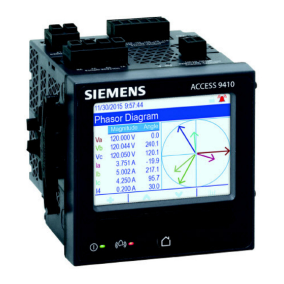
/ RMS *100% TDD = H / Demand *100% See ION Reference, available from www.usa.siemens.com/pds, for details about the Harmonics Measurement module. Phasors Phasors are used to represent the voltage and current magnitude and angles. The length of the lines in the phasor diagram represent the relative magnitude of the voltages with respect to the other phase voltages, and the currents with respect to the other phase currents. -
Page 193: Power Quality Standards Compliance
Quality Aggregator, Harmonics Measurement, Disturbance Analyzer, Symmetrical Components, and Sag/Swell. See the IEC 61000-4-30 compliance and ION meters technical note, available from www.usa.siemens.com/pds, for details. EN 50160 The EN 50160 framework includes ION modules, such as: Harmonics Evaluation and Voltage Harmonics. -
Page 194: Disturbance Direction Detection Overview
Power quality 9410 series - User manual Disturbance direction detection overview Your meter has disturbance direction detection capabilities to help you determine the location of a power system disturbance. When a disturbance occurs, the meter analyzes the disturbance information to determine the direction of the disturbance relative to the meter. -
Page 195: Disturbance Direction Detection Events
ION Setup. NOTE: You can view your meter’s event log through ION Setup, the meter webpages or display. See ION Reference, available from www.usa.siemens.com/pds, for more information about the Disturbance Direction Detection module. -
Page 196: Waveforms On The Meter Webpages
Ethernet gateway connections. See the COMTRADE and ION technology technical note, available from www.usa.siemens.com/pds, for details. Waveforms on the meter webpages You can use the waveform viewer on the meter’s webpages to view waveforms generated as a result of power quality events. -
Page 197: Viewing Waveforms On Meter Webpages
9410 series - User manual Power quality Select the COMTRADE module to view (COMTRADE_1 is set up by default; you can also set up COMTRADE_2 or COMTRADE_3) Select the particular COMTRADE waveform to view Show/hide parameters View details Zoom in/out Viewing waveforms on meter webpages Use the waveform viewer on your meter’s webpages to view the meter’s COMTRADE waveform files. -
Page 198: Burst Data Logging
Power quality 9410 series - User manual To view waveforms on meter webpages: 1. Open a browser and go to the IP address for your meter, entering valid login credentials when requested. 2. Navigate to Monitoring > Waveforms. A screen displays with accordion menus for three COMTRADE modules (regardless of whether or not that COMTRADE module is being created by the meter). -
Page 199: Data Recorder Burst Data
9410 series - User manual Power quality Burst data logging is analogous to continuous shooting mode or “burst mode” in photography. An understanding of pre and post event data assists in the analysis of undesired power quality events such as sags or swells. Burst logging is typically used for high-speed RMS (half-cycle) data capture, but the data recorder supports standard speed (1-second) recording as well, depending on the ION modules connected to the inputs of the Data Recorder module. -
Page 200: Waveform Capture
Power quality 9410 series - User manual Use the system frequency to calculate the number of records needed to capture 1 second of data: • For 60 Hz, total number of records per second = 60 cycles/second x 2 half-cycles = 120 •... -
Page 201: Delayed Waveform Capture
9410 series - User manual Power quality Waveform recording triggered Waveform record captured at trigger Delayed waveform capture The meter’s Waveform Recorder modules support delayed waveform capture. The Waveform Recorder module’s Record Delay Cycles setup register specifies how many cycles to delay the waveform capture after the Record input is triggered. This is for capturing post- trigger waveform data. - Page 202 Power quality 9410 series - User manual Both Pre-trigger Records and Post-trigger Records are set to zero by default. To configure the waveform recorder for extended waveform capture, either or both of these setup registers must be set to a non-zero positive integer value. If you do this, you must also set the Record Delay Cycles setup register to zero in order to properly configure the extended waveform capture.
- Page 203 9410 series - User manual Power quality The waveform log set for the extended waveform capture = [pre-trigger records] + [actual trigger record] + [post-trigger records]. The total waveform records captured in this example is 2 + 1 + 6 = When extended waveform capture is enabled, both Buffer Depth and Depth setup registers must be set to a positive integer multiple of the waveform log set.
-
Page 204: Logging
You can also configure the meter to email data from the logging frameworks. See the Internal Email Client Feature technical note, available from www.usa.siemens.com/pds, for details. Meter events are recorded in the meter’s onboard event log. You can also configure the meter to record events to an external SysLog (systems log) server. -
Page 205: Historic Data Logs
9410 series - User manual Logging • Log depth = 3360 records (35 days) • Interval = 900 seconds (15 minutes) By default, it logs the following values: Parameter Description kWh del int Interval kWh delivered kWh rec int Interval kWh received kVARh del int Interval kVARh delivered kVARh rec int... -
Page 206: Loss Log
Logging 9410 series - User manual Loss log The Loss Log (Data Rec 9) is configured to record loss values. Factory settings for this data recorder: • Log depth = 3360 records (35 days) • Interval = 900 seconds (15 minutes) By default, it logs the following values: Parameter Description... -
Page 207: Energy And Demand Log
9410 series - User manual Logging Energy and demand log The EgyDmd Log (Data Rec 10) records energy and demand data used by energy management software to generate reports. Factory settings for this data recorder: • Log depth = 3360 records (35 days) •... -
Page 208: Sg/Sw Hs Log
The meter logs EN 50160 counter data for present and previous observation periods as well as EN 50160 events. See the Power Quality: ION Meters and EN50160 technical note, available from www.usa.siemens.com/pds, for details. IEC 61000-4-30 compliance logs The IEC 61000-4-30 compliance logs are used to log parameters related to the International Electrotechnical Commission’s IEC 61000-4-30 standards’... - Page 209 9410 series - User manual Logging 4-30 3s RMS Log (Data Rec 38) PqFlag 2s ivd I1 3s V1 OverDev 3s V3 OverDev 3s V1 3s I2 3s V2 UnderDev 3s V2 3s I3 3s V2 OverDev 3s V3 3s V1 UnderDev 3s V3 UnderDev 3s 4-30 10mRMS Log (Data Rec 16)
-
Page 210: Ieee 519 Compliance Logs
V Intrp DrtnAll (voltage interruption duration - all voltages) See the IEC 61000-4-30 compliance and ION meters technical note, available from www.usa.siemens.com/pds, for details. IEEE 519 compliance logs The IEEE 519 compliance logs are used to record IEEE 519 compliance parameters:... -
Page 211: Waveform Recording
9410 series - User manual Logging Parameter Description Information only. This is automatically calculated, and displays Log Memory how much memory the log uses based on the Log Interval and Log Depth Information only. This is automatically calculated, and displays Log Storage how much total memory is left after subtracting the Log Memory usage... -
Page 212: Key Terms
A power event where the voltage or current rises above the Swell nominal value. See ION Reference, available from www.usa.siemens.com/pds, for more information on the Waveform Recorder module and its settings. Default waveform recording configuration The meter’s default framework includes factory-configured waveform logs (waveform recorders). -
Page 213: Comtrade Modules
9410 series - User manual Logging Waveform recorder Description I2 current waveforms recorded during a defined sag or Wfm Rc I2-Sg/Sw (Wform Rec 6) swell event. I3 current waveforms recorded during a defined sag or Wfm Rc I3-Sg/Sw (Wform Rec 7) swell event. - Page 214 Info Only. To disable the alarm and the event, set the alarm priority to None. See ION Reference, available from www.usa.siemens.com/pds, for more information about the Event Log Controller module and event priorities for specific ION modules.
-
Page 215: Syslog
9410 series - User manual Logging Syslog Syslog uses the User Datagram Protocol (UDP) to transport event log information from the meter directly to a centralized syslog server. The syslog server can receive logs from multiple devices, including meters, then store and filter the log information as needed. -
Page 216: Advanced Log Setup And Memory Optimization
Logging 9410 series - User manual Syslog severity ION event priority name ION event priority range 2 - Critical condition High 192–255 4 - Warning condition Medium 128–191 5 - Normal but significant 64–127 condition 6 - Informational None 0–63 Advanced log setup and memory optimization You can configure your meter’s logs to help ensure the integrity of critical data and to optimize the meter’s memory usage. -
Page 217: Log Interval Configuration
9410 series - User manual Logging Log interval configuration You can configure the logging interval, which is how frequently records are logged. You can change the logging intervals for most logs using the ION Setup Assistant Logging > Memory screen. Changing the interval for other logs (for example, logs that are related to standards or triggered by disturbances) is an advanced procedure that involves using the Advanced mode of ION Setup to modify settings in the module that is linked to the log’s Record input. -
Page 218: Log Buffer Configuration
Logging 9410 series - User manual Log buffer configuration The log buffer depth is the maximum number of records that can be stored in the meter’s short- term memory (RAM) for a particular log. After records are captured in the log buffer in the meter’s short-term memory, they are replicated to the long-term memory. - Page 219 NOTE: The Insert Outage Records functionality does not work if the data recorder is configured as partially buffered. In order to use this functionality, you must configure the data recorder to be fully buffered. See ION Reference, available from www.usa.siemens.com/pds, for more information about configuring the Data Recorder module.
- Page 220 Logging 9410 series - User manual Log buffer Long-term memory Total available space in the log buffer (for example, 20 records) Example: Resulting gaps in data when a partially buffered log is full In the graphic on the left, the log buffer (A) is full, and the oldest record has not replicated to the long-term memory yet.
-
Page 221: Changing Log Interval And Depth Settings Using Ion Setup
9410 series - User manual Logging Record that cannot be logged because log buffer is full (this record is lost) Record moving from short-term memory to long-term memory New record at next interval Changing log interval and depth settings using ION Setup You can configure log intervals, log depths and buffer depths to optimize your memory usage. - Page 222 Logging 9410 series - User manual NOTE: If you receive a message stating that there is not enough memory when you change a log’s configuration, check the configuration of your meter’s other logs. You may not have enough RAM, or short-term memory, to allow for the new configuration. You may need to use Advanced mode to check the detailed configuration of your logs.
-
Page 223: Time And Timekeeping
Time Protocol (PTP) leader. See the Time Synchronization and Timekeeping technical note, available from www.usa.siemens.com/pds, for details. See ION Reference, available from www.usa.siemens.com/pds, for a detailed description of the Clock module operation. Internal clock temperature compensation The time accuracy of the meter has been improved by compensating for clock drift if the meter’s operating temperature falls outside the optimum temperature range. -
Page 224: Supported Time Synchronization Sources
Time and timekeeping 9410 series - User manual Supported time synchronization sources Several time synchronization sources are available to your meter. Time sync Description source Meter Configuration software can manually synchronize the time of your meter configuration based on the clock of the computer running the configuration software. software (ION Configuration software synchronization is usually performed when the meter Setup) -
Page 225: Clock Source Time Quality Flag
9410 series - User manual Time and timekeeping Setting option Description The meter monitors the ISO Grid Operation line frequency, and adjusts the one second period based on the measured line frequency. All devices connected to the grid network are synchronized to maintain a consistent time base. -
Page 226: Star Network Topology
Time and timekeeping 9410 series - User manual Parameter Setting Description A transparent clock that supports the use of the end-to- End to End PTP device type end delay measurement mechanism between slave transparent clock clocks and the leader clock. A clock that provides time information using the Peer delay 2 step... -
Page 227: Configuring Time Information Using Ion Setup
9410 series - User manual Time and timekeeping Configuring time information using ION Setup You can set the time and date and configure the time synchronization settings using ION Setup. NOTE: The clock screen is where you set the start day of the week for the time of use feature. NOTE: You must manually adjust the date and time information if the device is installed in a different time zone location from the computer running ION Setup. - Page 228 Time and timekeeping 9410 series - User manual Parameter Value Description Sets which device port accepts time synchronization messages. Time synchronization messages on other ports are ignored. For GPS time synchronization, set the Time Sync Source to COM1. COM1, ETHERNET, For SNTP/NTP time synchronization, set the ETHERNET - ION, Time Sync Source to ETHERNET.
-
Page 229: Configuring Time Information Using The Display
9410 series - User manual Time and timekeeping Parameter Value Description NTP: specifies NTP time synchronization. SNTP: specifies SNTP time synchronization. Enable NTP NOTE: SNTP is recommended for revenue-related NTP, SNTP, No applications. Time Sync No: neither NTP nor SNTP time synchronization are used. - Page 230 Time and timekeeping 9410 series - User manual Date and time setup Parameter Values Description Time Format 12 H, 24 H Specifies how the time is displayed. MM/DD/YYYY, Date Format DD/MM/YYYY, Specifies how the date is displayed. YYYY/MM/DD Sets the time zone of the meter’s location, TZ Offset -12:00:00 to 13:00:00 relative to UTC.
-
Page 231: Measurements
9410 series - User manual Measurements Measurements Energy Your meter provides bi-directional, 4-quadrant, revenue accurate energy metering: • kWh, kVARh, kVAh delivered and received • kWh, kVARh, kVAh net (delivered minus received) • kWh, kVARh, kVAh total (delivered plus received) •... -
Page 232: Min/Max Recording
Measurements 9410 series - User manual • Individual harmonics (including magnitude, phase angle phase and inter-harmonics) up to the harmonic • Total even harmonic distortion (TEHD), total odd harmonic distortion (TOHD) • Total harmonic distortion (THD), total demand distortion (TDD) •... -
Page 233: Power Factor (Pf)
9410 series - User manual Measurements Power factor (PF) Power factor (PF) is the ratio of real power (P) to apparent power (S). PF is provided as a number between -1 and 1 or as a percentage from -100% to 100%, where the sign is determined by the convention. -
Page 234: Current Phase Shift From Voltage
Measurements 9410 series - User manual The units for power are watts (W or kW) for real power P, vars (VAR or kVAR) for reactive power Q, and volt-amps (VA or kVA) for apparent power S. Positive real power P(+) flows from source to load, and negative real power P(-) flows from the load to the power source. -
Page 235: Power Demand
9410 series - User manual Measurements Current and voltage in phase (resistive) Current leads voltage (capacitive) Current lags voltage (inductive) Power demand Power demand is a measure of average power consumption over a fixed time interval. NOTE: If not specified, references to demand are assumed to mean power demand. 7EN05-0336-09... -
Page 236: Peak Demand
See the ION Setup online help for instructions on how to configure demand peak and the demand reset lockout period on your meter. See ION Reference, available from www.usa.siemens.com/pds, for detailed information on how Sliding Window Demand modules measure and calculate demand values. -
Page 237: Incremental Energy
9410 series - User manual Measurements Sliding window (rolling block) Incremental energy Incremental energy allows you to define a start time, end time, and the time interval (increments) for incremental energy accumulation. At the end of each interval, the energy accumulated during that period is stored. By default, the meter only records the previous interval’s incremental energy and the instantaneous energy accumulations in the active interval. -
Page 238: Example: Incremental Energy
Measurements 9410 series - User manual Incremental energy helps provide information for analyzing energy and power usage against present or future utility rates, and is useful for measuring energy consumption by shift or for a specific process. When configuring incremental energy, shorter incremental energy periods provide more granular data which can make the data easier to use for comparison purposes. -
Page 239: Conditional Energy
9410 series - User manual Measurements 4. Select Status and click Edit. The Incremental Energy Setup screen is displayed. 5. Select Enable to display parameters for configuration. 6. Select the parameter to configure. NOTE: Configuring any parameter resets the incremental energy values recorded by your meter. -
Page 240: Trending And Forecasting Overview
For your meter’s trending and forecasting feature to work, you only need to give the meter time to accumulate data. See ION Reference, available from www.usa.siemens.com/pds,for more information about the Trending and Forecasting module. - Page 241 9410 series - User manual Measurements 1. Log in to your meter’s webpages. 2. Click Monitoring > Trending & Forecasting. 3. Select the Target and Interval. The graph for the selected data is displayed. 7EN05-0336-09...
-
Page 242: Resets
Resets 9410 series - User manual Resets Resets overview Resets allow you to clear accumulated parameters stored on your meter, reinitialize the meter or reinitialize meter accessories. Meter resets clear your meter’s onboard data logs and other related information. Resets are typically performed after you make changes to the meter’s basic setup parameters to clear invalid or obsolete data to prepare the meter for active service. -
Page 243: Resetting The Meter Using Ion Setup
9410 series - User manual Resets Reset Description • Clears all cumulative and derived quantities from the meter, including: demand, peak demand, energy, and revenue parameters. • Clears meter event and waveform logs. Master Reset • Clears COMTRADE waveform records stored in the meter’s internal SFTP site. -
Page 244: Resetting The Meter Using The Meter Webpages
Resets 9410 series - User manual To reset the meter using ION Setup: 1. Start ION Setup. 2. Open the Setup Assistant for your meter. 3. Click Verification. 4. Select Normal Mode and click Display. 5. Select the desired tab in the Normal Mode dialog box. Depending on the tab selected, different resets are available. -
Page 245: Resetting The Meter Using The Display
9410 series - User manual Resets 3. Click Reset for the values you want to clear. Parameter Description Clears all cumulative and derived quantities from the meter, including: demand, peak demand, energy, and revenue parameters. Clears meter event and waveform logs. Master Reset Clears COMTRADE waveform records stored in the meter’s internal SFTP site. - Page 246 Resets 9410 series - User manual NOTICE DATA LOSS Failure to follow these instructions can result in data loss. Ensure all important data from the device has been retrieved before performing a reset. To reset the meter using the display: 1. Press the Home button on the display. 2.
- Page 247 9410 series - User manual Resets 5. Press the up and down buttons simultaneously. 6. Press the Select icon to accept the change. When you select Master Reset, the message all recorded data will be lost. Reset selected parameters? is displayed. 7.
-
Page 248: Firmware Upgrades
9410 series - User manual Firmware upgrades Firmware upgrades overview It is recommended to upgrade Siemens 9410 advanced power quality meters to the latest firmware version. Firmware version pre-v2.1.0 Before upgrading to the latest firmware version, firmware version 2.1.0 must have been previously installed. -
Page 249: Meter Firmware Upgrade Prerequisites
9410 series - User manual Firmware upgrades If Advanced security was used before upgrading meter firmware to v3.0.0, Advanced security is enabled. RECOMMENDATION: Use Advanced security mode. Legacy security Legacy security Legacy security Legacy security support password support password support username support password range limit... -
Page 250: Back Up Accumulated Energy Values
Download latest ION Setup To upgrade meter firmware, the most recent version of ION Setup is required. 1. Go to www.usa.siemens.com/pds and locate the latest version of ION Setup. 2. Download the installation file, then run it to upgrade ION Setup. -
Page 251: Option 1 (Recommended) - Upgrading Using Zip File
9410 series - User manual Firmware upgrades Option 1 (recommended) – Upgrading using ZIP file This is the recommended method of upgrading your meter. This method can also be used for sequential device upgrades. Any digital and analog outputs associated with your device may change state during a firmware upgrade. - Page 252 Firmware upgrades 9410 series - User manual 6. Select the components you want to upgrade. For example: 9410 firmware V3.0.0 package to be applied in the order listed: 9410_upgradeAgent_V002.001.000.upx (not required if already applied) 9410_V003.000.000.upx Factory V2.2.0.0.0 template is the meter template that is programmed to the meter after the firmware upgrade is complete.
-
Page 253: Option 2 - Upgrading Using Individual Upgrade Files
US2:948DISP96 display. Upgrading option module firmware You can upgrade option module using ION Setup or directly through the meter's internal SFTP site. 1. Go to www.usa.siemens.com/pds and search for the US2:948M2AO4AI or US2:948M2DO6DI firmware file. 2. Download the firmware file. 7EN05-0336-09... -
Page 254: Loading Option Module Firmware Using Ion Setup
Upload firmware to option modules using ION Setup over an Ethernet connection. Each option module must be upgraded individually. Prerequisites: • Option module firmware upgrade (.S19) file(s). Go to www.usa.siemens.com/pds to download upgrade files. • Option module is connected to the meter. -
Page 255: Loading Option Module Firmware Using Sftp
Upload firmware to your meter’s option modules by loading the firmware upgrade file onto your meter’s internal SFTP site. Each option module must be upgraded individually. Prerequisites: • Option module firmware upgrade (.S19) file(s). Go to www.usa.siemens.com/pds to download upgrade files. • Option module is connected to the meter. -
Page 256: Maintenance
9410 series - User manual Maintenance Maintenance overview The meter does not contain any user-serviceable parts. If the meter requires service, contact your local Siemens Technical Support representative. NOTICE METER DAMAGE Failure to follow these instructions can result in equipment damage. - Page 257 NOTE: Do not allow liquids to enter the device through ventilation slots, connectors, or other openings. • If you are not certain about how to remove abrasive contaminants from the meter or its accessories, contact Support or your Siemens representative. Improperly removing contaminants and pollution may void the warranty. To clean the display: •...
-
Page 258: Device-Specific Information
You can use the device’s Modbus map and Modbus commands to read the Modbus Product ID. See ION Reference, available from www.usa.siemens.com/pds, for more information on the Factory module. -
Page 259: Revenue
See the ION Device Template Reference, available from www.usa.siemens.com/pds, for a complete listing of revenue-locked features, settings and meter data. See the meter’s catalog pages, available from www.usa.siemens.com/pds, or consult your local Siemens representative for information about your device, its options and accessories. -
Page 260: Revenue-Locking Summary
Revenue 9410 series - User manual Revenue-locking summary You must configure and revenue lock your meter before installing it. • Unlock your revenue meter if it is locked. • Configure the required revenue settings specific for installation. NOTE: If you are using ION Setup to configure your meter, allow for any communication delays before removing power to your meter. -
Page 261: Revenue Locking Your Meter
9410 series - User manual Revenue LED behavior Revenue lock status The meter is revenue locked. New revenue lock state is pending; power cycle your meter to set the Flashing revenue lock to on or off. Revenue locking your meter You can lock and unlock your meter using the revenue lock switch located on the meter base. -
Page 262: Time Of Use
See the ION Setup online help, available from www.usa.siemens.com/pds, for instructions on how to configure TOU on your meter. See ION Reference, available from www.usa.siemens.com/pds, for a description of the Time of use module and its settings. Energy pulsing LED behavior The visible and infrared LEDs are configured by default to pulse based on energy measured by the meter. -
Page 263: Verifying Accuracy
For a list of accuracy standards that your meter complies to, contact your local Siemens representative or download the meter brochure from www.usa.siemens.com/pds. -
Page 264: Environment
Your meter complies with and meets the requirements of these energy metering standards. For a list of accuracy standards that your meter complies with, contact your local Siemens representative or download the meter brochure from www.usa.siemens.com/pds. -
Page 265: Verifying Accuracy Test Meter Settings
9410 series - User manual Verifying accuracy Verifying accuracy test meter settings Your meter‘s power system and other parameters must be configured for accuracy testing. Meter parameter Value Volts mode 4W-Wye (4 wire Wye) PT/CT correction Disabled Verifying accuracy test The following tests are guidelines for accuracy testing your meter;... -
Page 266: Calculate The Number Of Required Pulses
Verifying accuracy 9410 series - User manual Reference device or energy standard Test voltage and current source Meter under test 2. Connect the control equipment used for counting the standard output pulses using one of these methods: Option Description Energy pulsing Align the red light sensor on the standard test bench armature over the energy pulsing LED. -
Page 267: Percentage Error Calculation For Accuracy Verification Testing
NOTE: If accuracy verification reveals inaccuracies in your meter, they may be caused by typical sources of test errors. If there are no sources of test errors present, please contact your local Siemens representative. Typical sources of test errors If you see excessive errors during accuracy testing, examine your test setup and test procedures to eliminate typical sources of measurement errors. -
Page 268: Accuracy Verification Test Points
Verifying accuracy 9410 series - User manual • Inadequate meter control power, resulting in the meter resetting during the test procedure. • Ambient light interference or sensitivity issues with the optical sensor. • Unstable power source causing energy pulsing fluctuations. •... -
Page 269: Troubleshooting
• Enter meter username: User1 and Password: [password used before upgrade to firmware v3.0.0]. Using Vista software and after Go to www.usa.siemens.com/pds password is entered, access is not and search for support to get Meter recently granted. assistance with troubleshooting. -
Page 270: Option Module Troubleshooting
See ION Reference, available from www.usa.siemens.com/pds, for more information about the Factory and Diagnostics modules. Technical assistance Go to www.usa.siemens.com/pds and search for support to get assistance with troubleshooting. Have the meter model, serial number and firmware version information ready. See "Device- specific information"... -
Page 271: 9410 Specifications
This section provides additional specifications for your meter and accessories. NOTE: The information contained in this section is subject to change without notice. You can download updated documentation from www.usa.siemens.com/pds or contact your local Siemens representative for the latest updates. - Page 272 9410 specifications 9410 series - User manual Active power (P) IEC 61557-12 Class 0.2 Reactive power (Q IEC 61557-12 Class 1 Apparent power (S IEC 61557-12 Class 0.2 Apparent energy (E IEC 61557-12 Class 0.2 Current (I) IEC 61557-12 Class 0.2 Voltage (U) IEC 61557-12 Class 0.2 Frequency (f)
- Page 273 9410 series - User manual 9410 specifications Control power AC control power 50/60 Hz ± 10%: 90–415 V ± 10% Operating range 400 Hz: 90–120 V ± 10% max: 7.2 W/18 VA @ 415 V (45–65 Hz) Burden (meter only) max: 4.5 W/8 VA @ 120 V (400 Hz) max: 18 W/36 VA @ 415 V (45–65 Hz) Burden (fully optioned meter)
-
Page 274: Environmental Characteristics
9410 specifications 9410 series - User manual Response time 20 ms Minimum pulse width 20 ms ON: ≤ 2.5 mA Current draw OFF: ≤ 0.5 mA Voltage ON state 4–30 V AC/4–60 V DC Voltage OFF state 0–1.4 V AC/0–2.0 V DC IRIG-B00x format (unmodulated IRIG-B time code) IRIG-B Coded expressions 0 to 7 are supported but the year data is... -
Page 275: Emc (Electromagnetic Compatibility)
9410 series - User manual 9410 specifications EMC (electromagnetic compatibility) EMC standards IEC 62052-11, IEC 61326-1 Immunity to electrostatic IEC 61000-4-2 discharge Immunity to radiated fields IEC 61000-4-3 Immunity to fast transients IEC 61000-4-4 Immunity to surges IEC 61000-4-5 Immunity to conducted IEC 61000-4-6 disturbances Immunity to power frequency... -
Page 276: Rs-485 Communications
9410 specifications 9410 series - User manual Connector type Unshielded RJ45 modular connector (2) Mode 10Base-T, 100Base-TX, Auto-MDIX Data rate up to 100 Mbps Maximum simultaneous transfer connections (sessions): 2 SFTP Default timeout period: 90 seconds IEC 61850 maximum simultaneous client connections RS-485 communications Number of ports Cable type... -
Page 277: Option Modules
9410 series - User manual 9410 specifications Environment Front: IP54 IP degree of protection Rear: IP30 Option modules See your option module’s installation guide for additional option module specifications. US2:948M2AO4AI Analog (2 out, 4 in) Maximum number of modules < 300 Ω (current mode) Input resistance >... - Page 278 9410 specifications 9410 series - User manual Advanced security user Up to 50 users accounts 1 – Meter start up time is expressed as the typical elapsed time from the application of control power to the result indicated in the description field. 7EN05-0336-09...
-
Page 279: Open Source Software Components
9410 series - User manual Open source software components Open source software components This Siemens product is provided with certain open source software components (collectively, “OSS”) developed by third parties. The OSS is licensed in accordance with the OSS license terms set forth below. - Page 280 Open source software components 9410 series - User manual "Object" form shall mean any form resulting from mechanical transformation or translation of a Source form, including but not limited to compiled object code, generated documentation, and conversions to other media types. "Work"...
- Page 281 9410 series - User manual Open source software components 2. You must cause any modified files to carry prominent notices stating that You changed the files; and 3. You must retain, in the Source form of any Derivative Works that You distribute, all copyright, patent, trademark, and attribution notices from the Source form of the Work, excluding those notices that do not pertain to any part of the Derivative Works;...
- Page 282 Open source software components 9410 series - User manual 9. Accepting Warranty or Additional Liability. While redistributing the Work or Derivative Works thereof, You may choose to offer, and charge a fee for, acceptance of support, warranty, indemnity, or other liability obligations and/or rights consistent with this License. However, in accepting such obligations, You may act only on Your own behalf and on Your sole responsibility, not on behalf of any other Contributor, and only if You agree to indemnify, defend, and hold each Contributor harmless for any liability incurred by, or claims asserted against, such Contributor by...
- Page 283 Operating hours: 8:00 am - 5:00 pm Eastern Time, Monday - Friday www.usa.siemens.com/pds Siemens is a registered trademark of Siemens AG. Windows is a trademark and Microsoft is a registered trademark of Microsoft Corporation. ION, Modbus and WebMeter are either trademarks or registered trademarks of Schneider Electric in France, the USA and other countries.
Need help?
Do you have a question about the 9810 Series and is the answer not in the manual?
Questions and answers