Sign In
Upload
Download
Table of Contents
Contents
Add to my manuals
Delete from my manuals
Share
URL of this page:
HTML Link:
Bookmark this page
Add
Manual will be automatically added to "My Manuals"
Print this page
×
Bookmark added
×
Added to my manuals
Manuals
Brands
Siemens Manuals
Measuring Instruments
9510
Installation manual
Siemens 9510 Installation Manual
Power meter
Hide thumbs
Also See for 9510
:
User manual
(4 pages)
1
2
3
4
5
6
7
8
9
10
11
12
13
14
15
16
17
18
19
20
21
22
23
24
25
26
27
28
Table Of Contents
29
page
of
29
Go
/
29
Contents
Table of Contents
Bookmarks
Table of Contents
Standards Compliance
Installation Considerations
FCC Notice
Available Options
Before You Begin
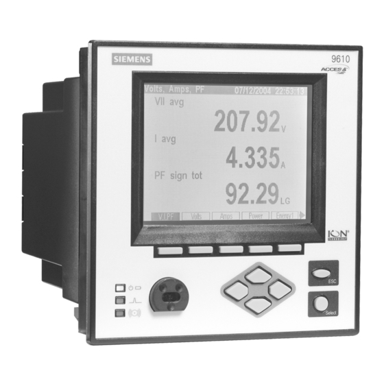
Meter Overview
Unit Dimensions
Step 1: Mount the Meter
Digital Inputs
Digital Inputs (Meter Ordering Option): DI1 - DI8
Analog Inputs (Meter Ordering Option): AI1 to AI4
Analog Outputs (Meter Ordering Option): AO1 to AO4
Single Phase Connection Diagram
Using Potential Transformers
RS-232 Connections (COM1)
RS-485 Connections (COM1 and COM2)
Infrared Connections (COM4)
Ethernet Connections (if Equipped)
Internal Modem Connection (COM3 if Equipped)
Step 6: Wire the Power Supply
Step 7: Power up the Meter
Phasor Diagrams
Advertisement
Quick Links
1
Standards Compliance
2
Installation Considerations
3
Meter Overview
4
Rs-485 Connections (Com1 and Com2)
5
Rs-232 Connections (Com1)
6
Ethernet Connections (if Equipped)
7
Step 7: Power up the Meter
Download this manual
9510 / 9610 Power Meter
Installation Guide
Table of
Contents
Previous
Page
Next
Page
1
2
3
4
5
Advertisement
Table of Contents
Need help?
Do you have a question about the 9510 and is the answer not in the manual?
Ask a question
Questions and answers
Related Manuals for Siemens 9510
Measuring Instruments Siemens ACCESS 9510 User Manual
(4 pages)
Measuring Instruments Siemens 9200 Installation & Operation Manual
Power meter (29 pages)
Measuring Instruments Siemens 9200 Features Manual
Power meter (24 pages)
Measuring Instruments Siemens 9410RC User Manual
9410 series (172 pages)
Measuring Instruments Siemens 9410DC User Manual
9410 series (172 pages)
Measuring Instruments Siemens 9410TC User Manual
9410 series (172 pages)
Measuring Instruments Siemens 9330 series Product Manual
Power meter (12 pages)
Measuring Instruments Siemens 9350 series Product Manual
Power meter (12 pages)
Measuring Instruments Siemens 9610 Installation Manual
Power meter (29 pages)
Measuring Instruments Siemens 9810 Series User Manual
Power meter (218 pages)
Measuring Instruments Siemens 9810 Series User Manual
(283 pages)
Measuring Instruments Siemens US2:9810T24V User Manual
(300 pages)
Measuring Instruments Siemens 9700 Installation Instructions Manual
Power meter (45 pages)
Measuring Instruments Siemens 3WN1 3ZX1812-0WX31-9BN1 Operating Instructions Manual
The mechanical trip indicator or reclosing lockout (10 pages)
Measuring Instruments Siemens ACCESS 9340 Reference Manual
(264 pages)
Measuring Instruments Siemens 9410 Series User Manual
(202 pages)
This manual is also suitable for:
9610
Table of Contents
Save PDF
Print
Rename the bookmark
Delete bookmark?
Delete from my manuals?
Login
Sign In
OR
Sign in with Facebook
Sign in with Google
Upload manual
Upload from disk
Upload from URL


Need help?
Do you have a question about the 9510 and is the answer not in the manual?
Questions and answers