Table of Contents
Advertisement
Quick Links
A l l t e s t I n s t r u me n t s , I n c .
5 0 0 C e n t r a l A v e .
F a r mi n g d a l e , N J 0 7 7 2 7
P : ( 7 3 2 ) 9 1 9 - 3 3 3 9
F : ( 7 3 2 ) 9 1 9 - 3 3 3 2
a l l t e s t . n e t
s s a l e s @ a l l t e s t . n e t
T h e t e s t & me a s u r e me n t
e q u i p me n t y o u n e e d a t
t h e p r i c e y o u w a n t .
A l l t e s t c a r r i e s t h e w o r l d ' s l a r g e s t s e l e c t i o n o f
u s e d / r e f u r b i s h e d b e n c h t o p t e s t & me a s u r e me n t
e q u i p me n t a t 5 0 % t h e p r i c e o f n e w .
O O u r e q u i p me n t i s g u a r a n t e e d w o r k i n g , w a r r a n t i e d , a n d
a v a i l a b l e w i t h c e r t i f i e d c a l i b r a t i o n f r o m o u r i n - h o u s e s t a f f
o f t e c h n i c i a n s a n d e n g i n e e r s .
• 1 0 + f u l l t i me t e c h n i c i a n s w i t h o v e r 1 5 0 y e a r s o f
s p e c i a l i z a t i o n
• 9 0 d a y w a r r a n t y & 5 d a y r i g h t o f r e t u r n o n a l l
e q u i p me n t
• • 1 - 3 y e a r w a r r a n t i e s f o r n e w a n d
p r e mi u m- r e f u r b i s h e d e q u i p me n t
• E v e r y u n i t t e s t e d t o O E M s p e c i f i c a t i o n s
• S a t i s f a c t i o n g u a r a n t e e d
Y o u h a v e p l a n s , w e w i l l h e l p y o u a c h i e v e t h e m.
A n y p r o j e c t . A n y b u d g e t .
t
G e t a q u o t e t o d a y !
C C a l l ( 7 3 2 ) 9 1 9 - 3 3 3 9 o r e ma i l s a l e s @a l l t e s t . n e t .
Advertisement
Table of Contents

Related Manuals for Tektronix PatternPro PPG1600


Summary of Contents for Tektronix PatternPro PPG1600
- Page 1 T h e t e s t & me a s u r e me n t e q u i p me n t y o u n e e d a t t h e p r i c e y o u w a n t . A l l t e s t I n s t r u me n t s , I n c .
- Page 2 Tektronix PPG1600, PPG3000, & PPG3200 PatternPro® Series Pattern Generator User Manual *P077109001* 077-1090-01...
- Page 4 Tektronix PPG1600, PPG3000, & PPG3200 PatternPro® Series Pattern Generator User Manual www.tek.com 077-1090-01...
- Page 5 Copyright © Tektronix. All rights reserved. Licensed software products are owned by Tektronix or its subsidiaries or suppliers, and are protected by national copyright laws and international treaty provisions. Tektronix products are covered by U.S. and foreign patents, issued and pending. Information in this publication supersedes that in all previously published material.
- Page 6 Tektronix, with shipping charges prepaid. Tektronix shall pay for the return of the product to Customer if the shipment is to a location within the country in which the Tektronix service center is located. Customer shall be responsible for paying all shipping charges, duties, taxes, and any other charges for products returned to any other locations.
-
Page 8: Table Of Contents
Table of Contents Important safety information ..................General safety summary ..................Service safety summary ..................Terms in this manual ..................Symbols and terms on the product ................. viii Preface ......................Features ......................Documentation ....................Getting started....................... Installation ...................... Controls and connectors ................... Functional verification ..................... - Page 9 Table of Contents Regular commands ....................Summary....................... Reference ......................:DIGital[1|2|3|4]:PATTern:LENGth................. :DIGital[1|2|3|4]:PATTern:TYPE ................:DIGital[1|2|3|4]:PATTern:PLENgth................ :DIGital[1|2|3|4]:PATTern:DATA ................:DIGital[1|2|3|4]:PATTern:HDATa ................:DIGital[1|2|3|4]:PATTern:SERRor ................. :DIGital[1|2|3|4]:PATTern:ERATe ................:DIGital[1|2|3|4]:PATTern:ERATe:STATe..............:DIGital[1|2|3|4]:PATTern:BSHift ................:DIGital[1|2|3|4]:SIGNal[:POS|:NEG]:CROSsover:[VALue] ........... :MMEMory:STORe:PDATa ................. :MMEMory:STORe:STATe ................. :MMEMory:LOAD:PDATa ................. :MMEMory:LOAD:STATe .................. :MMEMory:MOVE:PDATa ................. :MMEMory:MOVE:STATe.................. :MMEMory:DELete:PDATa................. :MMEMory:DELete:STATe ................. :MMEMory:CATalog:PDATa? ................
- Page 10 Table of Contents [:SOURce]:PM[1|2|3|4][:HF]:INTernal4:PLENgth ............[:SOURce]:PM[1|2|3|4][:HF]:INTernal4:STATe ............[:SOURce]:PM:LF[:INTernal3][:DEViation] ............. [:SOURce]:PM:LF[:INTernal3]:FREQuency ............. [:SOURce]:PM:LF[:INTernal3]:STATe ..............[:SOURce]:VOLTage[1|2|3|4][:POS|:NEG][:LEVel][:IMMediate]:[:AMPLitude]....[:SOURce]:VOLTage[1|2|3|4][:POS|:NEG][:LEVel][:IMMediate]:OFFSet ......[:SOURce]:VOLTage[1|2|3|4][:POS|:NEG][:LEVel][:IMMediate]:TERMination ....[:SOURce]:VOLTage[1|2|3|4][:LEVel][:IMMediate]:LINK ..........:SYSTem:ERRor[:NEXT]? .................. :TRIGger:SOURce ................... :TRIGger:LOCK ....................User service ......................Service offerings ....................General care ....................Preventive maintenance ..................Fuse replacement ..................... Repack the instrument for shipment ................
- Page 11 Table of Contents List of Figures Figure 1: Front panel controls and connectors ..............Figure 2: Rear panel connectors .................. Figure 3: Verification setup..................Figure 4: Clock (top) and data (bottom) waveforms ............Figure 5: Eye diagram for the PPG3200, 32 Gb/s, PRBS11..........Figure 6: Block diagram ..................
-
Page 12: Important Safety Information
Important safety information This manual contains information and warnings that must be followed by the user for safe operation and to keep the product in a safe condition. To safely perform service on this product, additional information is provided at the end of this section. - Page 13 Important safety information Power disconnect. The power cord disconnects the product from the power source. See instructions for the location. Do not position the equipment so that it is difficult to operate the power cord; it must remain accessible to the user at all times to allow for quick disconnection if needed.
-
Page 14: Service Safety Summary
Important safety information Provide a safe working environment. Always place the product in a location convenient for viewing the display and indicators. Avoid improper or prolonged use of keyboards, pointers, and button pads. Improper or prolonged keyboard or pointer use may result in serious injury. Be sure your work area meets applicable ergonomic standards. -
Page 15: Symbols And Terms On The Product
Important safety information Symbols and terms on the product These terms may appear on the product: DANGER indicates an injury hazard immediately accessible as you read the marking. WARNING indicates an injury hazard not immediately accessible as you read the marking. CAUTION indicates a hazard to property including the product. -
Page 16: Preface
The single unit multi-channel configurations provide aligned, pattern-independent data outputs that support testing of crosstalk immunity and multi-channel functionality. The PPG line can be paired with the Tektronix PED line of Error Detector products to provide a complete BER test capability. -
Page 17: Table I: Product Description
Preface External clock input Trigger output programmable as pattern trigger or clock/n Jitter insertion (option): High Frequency SJ/RJ/BUJ jitter insertion (Option HFJIT) Low frequency jitter insertion (Option LFJIT) External modulation input Save up to twenty-five user patterns in nonvolatile memory Save up to twenty-five generator setups in nonvolatile memory Touch screen graphical user interface &... -
Page 18: Documentation
PPG/PED Safety & Installation Manual, printed version shipped with the product This PPG1600, PPG3000, & PPG3200 Series PatternPro Pattern Generator User Manual (PDF versions only, downloadable from the Tektronix Web Site) Product datasheets (PDF versions only, downloadable from the Tektronix Web Site) Declassification &... - Page 19 Preface PPG1600, PPG3000, & PPG3200 Pattern Generator User Manual...
-
Page 20: Getting Started
Getting started Installation The instrument was carefully inspected electrically and mechanically before shipment. After unpacking all items from the shipping carton, check for any obvious signs of physical damage that may have occurred during transit (there might be a protective film over the display, which can be removed). Report damage to the shipping agent immediately. -
Page 21: Table 1: Power Requirements
Getting started Power requirements CAUTION. Operating the instrument on an incorrect line voltage can cause damage, possibly voiding the warranty. To avoid this, operate the instrument with the correct line voltage. The instrument operates from a single-phase line voltage listed in the following table. -
Page 22: Table 2: Maximum Operating Environmental Considerations
Getting started When rack mounting the instrument, ensure there is adequate airflow around the instrument rear, sides, and bottom to ensure proper cooling. Adequate airflow enables air temperatures within approximately one inch of the instrument surfaces to remain within specified limits under all operating conditions. Environmental The following table describes the maximum operating environmental ratings for your instrument. -
Page 23: Controls And Connectors
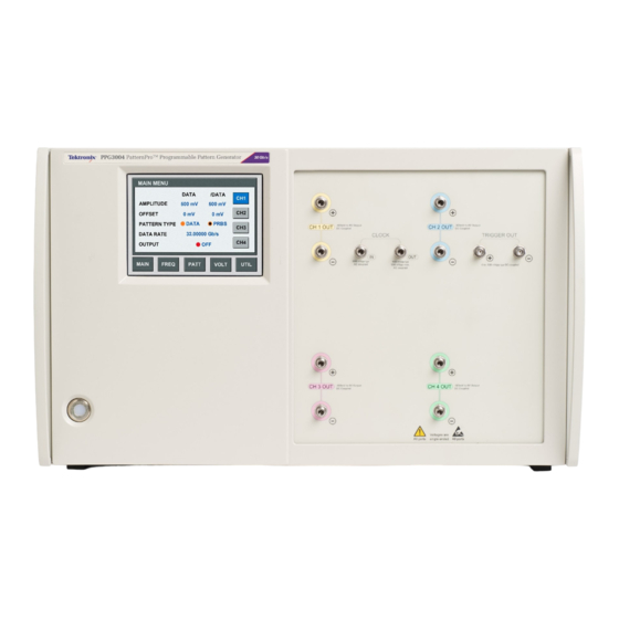
Controls and connectors Controls and connectors The following illustration and table describe the front panel controls and connectors. The illustration shows a 4-channel instrument; 1-channel and 2-channel instruments have fewer controls in different locations on the instrument. NOTE. The exact location and spacing of the Data Out connectors may be different depending on the instrument type or output options ordered with the instrument. -
Page 24: Figure 2: Rear Panel Connectors
Controls and connectors Table 3: Front panel controls and connectors (cont.) Item Description Data Out connectors (Ch2) Plus and minus Data outputs with 2.92 mm connectors (PPG1602, PPG1604, PPG3002 or PPG3004) or 2.4 mm connectors (PPG3202 or PPG3204) Data Out connectors (Ch3) Plus and minus Data outputs with 2.92 mm connectors (PPG1604, PPG3004) or 2.4 mm connectors (PPG3204) Data Out connectors (Ch4) - Page 25 Controls and connectors Table 4: Rear panel connectors (cont.) Item Description JITTER IN (Ch3) SMA Ch3 input for external jitter insertion (Option JIT) JITTER IN (Ch4) SMA Ch4 input for external jitter insertion (Option JIT) PPG1600, PPG3000, & PPG3200 Pattern Generator User Manual...
-
Page 26: Functional Verification
A typical setup for verifying the pattern generator operation is shown in the following figure. The diagram uses only the + side of all differential connections, the - side can be tested in the same manner. Use a Tektronix DSA8300 Digital Serial Analyzer Sampling Oscilloscope or similar for functional verification. -
Page 27: Power On And Verify Instrument Operation
Functional verification Power on and verify instrument operation The following steps assume the unit is connected as shown in the verification setup. NOTE. Note: The generator is internally temperature compensated for timing and output level continuously and automatically. Internal timing calibration will also take place whenever the frequency is set (either manually or through remote programming). -
Page 28: Verify The Eye Diagram
Functional verification Figure 4: Clock (top) and data (bottom) waveforms Verify the eye diagram 1. Select UTILITY. 2. Select TRIGGER. 3. Select TRIGGER TYPE = CLK/N. 4. Set N DIVISOR to 64. 5. Turn off the display on the oscilloscope channel 1 (clock signal). PPG1600, PPG3000, &... -
Page 29: Check Other Settings
Functional verification 6. Adjust the sampling oscilloscope amplitude, timing and display as needed. Output should be similar to the following figure. Figure 5: Eye diagram for the PPG3200, 32 Gb/s, PRBS11 Check other settings Access the remaining menus to experiment with other settings. PPG1600, PPG3000, &... -
Page 30: Input And Output Descriptions
Input and output descriptions Overview RF connectors Data and Clock front panel RF connectors are 2.92 mm (K type) for the PPG1600 and PPG3000 series. Data and clock connectors are 2.4 mm for the PPG3200 series. All other front panel RF connections are SMA. Connector torque Minimum: 2 in-lbs (0.226 N-m) -
Page 31: Data Outputs
Input and output descriptions Functional block diagram The basic functional blocks are shown in the following figure. Figure 6: Block diagram Data outputs Output range The instrument is designed to drive a 50 Ω load. The voltage window is adjustable over the range from -2 V to +3 V. -
Page 32: Specifications
Specifications All specifications apply to all models unless noted otherwise. PPG3200 data outputs There is a true and a complement output for each channel. Specifications apply to each output individually. Amplitude Each positive and negative differential output is independently programmable. Single-ended. -
Page 33: Ppg3000 & Ppg1600 Data Outputs
Specifications Termination voltage range -2.0 V to +3.3 V window. Programmable/adjustable. Applied by user via 50 Ω. This setting is used in cases where the load being driven is terminated at a level other than zero volts. The effect of the termination voltage on the output voltage is shown in the following figure. - Page 34 Specifications Termination voltage range -2.0 V to +3.3 V window. Programmable/adjustable. Applied by user via 50 Ω. This setting is used in cases where the load being driven is terminated at a level other than zero volts. The effect of the termination voltage on the output voltage is shown in the following figure.
-
Page 35: Data Patterns
Specifications Data patterns Pattern type Data (from memory) or PRBS. Length and type are individually settable on multi-channel generators. Data rate Programmable/adjustable Range. 1.5 Gb/s to 16 Gb/s, (PPG1600 series) 1.5 Gb/s to 30 Gb/s, (PPG3000 series) 1.5 Gb/s to 32 Gb/s (PPG3200 series) Resolution. -
Page 36: Clock Outputs
Specifications Clock outputs The clock outputs are single-ended, applicable for internal clock. The internal clock rate ranges from 15 GHz to 30 GHz (PPG3000 series) and 16 GHz to 32 GHz (PPG1600 and PPG3200 series). PPG1600 Clock output frequency. (Internal clock)/(n), n = 2,4,8, or 16 user programmable PPG3000 Clock output frequency. -
Page 37: Jitter Insertion
Specifications Jitter insertion The pattern generator can be ordered with built-in jitter options. The PPG3200 series are available with Option LFJIT and Option HFJIT; the PPG1600 and PPG3000 series are available with Option HFJIT only. The jitter insertion is the delay modulation of the data channels. -
Page 38: Table 5: Sj Modulation Range Curve Points
Specifications Built-in random noise Programmable from either the front panel touch screen or remote control. source Amplitude range. 0 to 5 ps Accuracy. ±10% typical Built-in BUJ source Programmable from either the front panel touch screen or remote control. Amplitude range. 0 to 50 ps Modulation data rates. -
Page 39: Trigger System
Specifications Trigger system The Trigger output provides either a pattern synchronous trigger signal or a clock/n signal. Trigger waveform Pattern mode trigger is synced to channel 1 pattern. Pattern mode. 1 pattern per trigger for pattern length = multiple of 64 64 patterns per trigger for other pattern lengths Clock/n mode. -
Page 40: Clock Inputs
Specifications Clock inputs The pattern generators allow the use of an external clock. The external clock must be a continuous 50% duty cycle clock. Frequency range 15 GHz to 30 GHz, (PPG3000 series) 16 GHz to 32 GHz, (PPG3200 series) Not applicable for the PPG1600 series. -
Page 41: Channel Skew
Specifications Channel skew The channel skew is the timing of the data outputs. Skew adjust Relative to nominal position PPG1600 and PPG3000. Range = ±50 ps Resolution = 100 fs PPG3200. Range = ±25 ps Resolution = 100 fs Pattern shift Advance or delay. -
Page 42: Physical Characteristics
Specifications Physical characteristics Front panel width (with 48.3 cm (19.0 in) mounting tabs) Height 1 & 2 channel. 13.3 cm (5.25 in) 4 channel. 27.9 cm (11.0 in) Width 45.1 cm (17.75 in) Depth (rack mount) 35.1 cm (13.8 in) Weight 1 &... - Page 43 Specifications PPG1600, PPG3000, & PPG3200 Pattern Generator User Manual...
-
Page 44: Graphical User Interface (Gui) Touch Screen
Graphical user interface (GUI) touch screen This unit is equipped with touch screen controls. All manual settings are accessed through this user interface. An example of the GUI is shown in the following figure. The following table gives a listing of where to find various parameters within the menu structure. - Page 45 Graphical user interface (GUI) touch screen Table 6: GUI menu parameter locations (cont.) Parameter Found in menu(s) PRBS Length PATTERN Output ON / OFF MAIN, VOLTS Recall Pattern PATTERN [SAVE] [RECALL] Recall Setup UTILITY [SAVE] [RECALL] Save Pattern PATTERN [SAVE] [STORE] Save Setup UTILITY [SAVE] [STORE] Skew...
-
Page 46: Remote Programming
Remote programming Remote programming USB interface All automated programming is accomplished through a USB TMC interface. Command information Sequential vs. overlapped All commands for instruments covered by this document are sequential commands. Sequential commands complete before the next is executed. This means that completion of any command can be verified by following it with any query. -
Page 47: Common Commands
*IDN? Read the instrument’s identification string. The returned string has the following format, it can be up to 72 characters long: “Tektronix Inc.Model code,SN,FWREV” Model code (see the following table for your instrument model.) SN = serial number FWREV = firmware revision... -
Page 48: Regular Commands
Regular commands Regular commands Summary The following table provides a summary of the remote control commands. Command Parameters Default Description DIGITAL subsystem :DIGital[1|2|3|4] :PATTern :LENGth <numeric> set/query Pattern (See page 32.) Length :TYPE DATA | PRBS PRBS set/query Pattern type (See page 32.) :PLENgth <numeric>... - Page 49 Regular commands Command Parameters Default Description [:STATe] OFF | ON set/query data output (See page 42.) enable/disable status :OUTPut :CLOCk:DIVider <numeric> varies programs the clock (See page 42.) divider output for the internal clock Sense subsystem :SENSe:ROSCillator :SOURce INTernal | set/query 10 MHz (See page 43.) EXTernal...
- Page 50 Regular commands Command Parameters Default Description :INTernal4:FREQuency <numeric> 2 GHz set/query internal HF (See page 47.) BUJ generator clock frequency :INTernal4:PLENgth <numeric> set/query internal HF (See page 47.) BUJ generator PRBS length :INTernal4:STATe OFF | ON set/query internal (See page 48.) HF BUJ jitter enable/disable status :PM:LF...
-
Page 51: Reference
Reference Reference :DIGital[1|2|3|4]:PATTern:LENGth Form Set & Query Parameters Numeric Value Coupling None None Range Coupling Default Description Programs the Pattern Length. This value is only relevant if the pattern type is DATA. For the one channel instruments, the length may be any integer from 2 through 4,194,304. In a two or four channel unit, the maximum pattern length per channel is 2,097,152. -
Page 52: Digital[1|2|3|4]:Pattern:plength
Reference :DIGital[1|2|3|4]:PATTern:PLENgth Form Set & Query Parameters 7 | 9 | 11 | 15 | 23 | 31 Value Coupling None Range Coupling None Default Description Programs the Pattern PRBS Length. PRBS Length is specified as 2 -1, where N is the specified value. -
Page 53: Digital[1|2|3|4]:Pattern:data
Reference :DIGital[1|2|3|4]:PATTern:DATA Form Set & Query Parameters <start address>,<bit count>,<data> <start address> is numeric, and is the bit number in pattern data memory of the first bit to write. <bit count> is the number of bits to write into pattern data memory. <data>... -
Page 54: Digital[1|2|3|4]:Pattern:hdata
Reference :DIGital[1|2|3|4]:PATTern:HDATa Form Set & Query Parameters <start address>,<bit count>,<data> <start address> is numeric, and is the bit number in pattern data memory of the first bit to write. <bit count> is the number of bits to write into pattern data memory. <data>... -
Page 55: Digital[1|2|3|4]:Pattern:serror
Reference :DIGital[1|2|3|4]:PATTern:SERRor Form Parameters None Value Coupling None Range Coupling None Default Description Inserts a single error into the data output. Error insertion works for either data patterns or PRBS patterns. If there is no pattern currently being output, for instance if the outputs are disabled, the command has no effect. -
Page 56: Digital[1|2|3|4]:Pattern:bshift
Reference :DIGital[1|2|3|4]:PATTern:BSHift Form Set & Query Parameters Numeric Value Coupling None Range Coupling None Default Description Shift the pattern by the specified number of bits relative to nominal position. Example Insert bit shift of 10 into the Ch 1 data output. :DIG1:PATT:BSH 10 :DIGital[1|2|3|4]:SIGNal[:POS|:NEG]:CROSsover:[VALue] Form... -
Page 57: Mmemory:store:pdata
Reference :MMEMory:STORe:PDATa Form Parameters String Value Coupling None Range Coupling None Default Description Store the current pattern data into the system memory. In a multi-channel unit, the pattern data running on all channels are stored. The pattern length and all pattern data up to the pattern length are stored. -
Page 58: Mmemory:load:state
Reference :MMEMory:LOAD:STATe Form Parameters String Value Coupling None Range Coupling None Default Description Recalls the instrument setting from a saved file in system memory. Every parameter of the instrument is recalled except for pattern data, pattern length and output enable status. The filename can be up to 8 characters long and is not case-sensitive. -
Page 59: Mmemory:delete:pdata
Reference :MMEMory:DELete:PDATa Form Parameters String Value Coupling None Range Coupling None Default Description Deletes an existing saved pattern data file in system memory. The filename can be up to 8 characters long and is not case-sensitive. Filenames must consist of only alphanumeric characters. -
Page 60: Mmemory:catalog:state
Reference :MMEMory:CATalog:STATe? Form Query Parameters None Value Coupling None Range Coupling None Default Description Get the list of instrument settings files stored in system memory. All the filenames stored in the system memory are returned as capital letters. Example Get the list of instrument settings files stored in system memory. :MMEM:CAT:STAT? :OUTPut0:SOURce Form... -
Page 61: Output[1|2|3|4]:Polarity
Reference :OUTPut[1|2|3|4]:POLarity Form Set & Query Parameters NORMal | INVerted Value Coupling None Range Coupling None Default NORMal Description Programs the polarity of the channel outputs. Example Set Ch 1 for inverted output :OUTPUT1:POLARITY INV :OUTPut[1|2|3|4][:STATe] Form Set & Query Parameters OFF | ON Value Coupling... -
Page 62: Sense:roscillator:source
Reference :SENSe:ROSCillator:SOURce Form Set & Query Parameters INTernal | EXTernal Value Coupling None Range Coupling None Default Description Programs the 10 MHz reference source. Example Set the 10 MHz reference source to use the internal reference. :SENSE:ROSCILLATOR:SOURCE INTERNAL [:SOURce]:FREQuency[:CW|:FIXed] Form Set &... -
Page 63: [:Source]:Pm[1|2|3|4][:Hf][:State]
Reference [:SOURce]:PM[1|2|3|4][:HF][:STATe] Form Set & Query Parameters OFF | ON Value Coupling None Range Coupling None Default Description Programs the overall channel jitter insertion enable/disable status. The HF sources are HF sine, random and external. If enabled, the external jitter source is enabled and the internal sources are set according to their individual controls. -
Page 64: [:Source]:Pm[1|2|3|4][:Hf]:Internal1:State
Reference [:SOURce]:PM[1|2|3|4][:HF]:INTernal1:STATe Form Set & Query Parameters OFF | ON Value Coupling None Range Coupling None Default Description Programs the channel internal HF sine jitter source enable/disable status. Both this setting and [:SOURce]:PM[1|2|3|4][:HF][:STATe] for a given channel must be on for HF sine jitter to be applied. -
Page 65: [:Source]:Pm[1|2|3|4][:Hf]:Internal4:Calibration
Reference [:SOURce]:PM[1|2|3|4][:HF]:INTernal4:CALibration Form Set & Query Parameters GAUSsian | CEI Value Coupling None Range Coupling None Default GAUS Description Programs the calibration source for the BUJ amplitude. BUJ amplitude is calibrated under two conditions; select the source closest to the current settings. The settings for each cal are given below. -
Page 66: [:Source]:Pm[1|2|3|4][:Hf]:Internal4:Frequency
Reference [:SOURce]:PM[1|2|3|4][:HF]:INTernal4:FREQuency Form Set & Query Parameters Numeric [Hz] Value Coupling None Range Coupling None Default 2 GHz Description Programs the clock frequency of the PRBS used to generate the BUJ jitter. Units are Hz. Example Set clock frequency of the channel 1 BUJ PRBS to 1.7 GHz. :PM1:INT4:FREQ 1.7GHz [:SOURce]:PM[1|2|3|4][:HF]:INTernal4:PLENgth Form... -
Page 67: [:Source]:Pm:lf[:Internal3][:Deviation]
Reference [:SOURce]:PM:LF[:INTernal3][:DEViation] Form Set & Query Parameters Numeric [UI] Value Coupling None Range Coupling LF Sine Jitter Frequency Default 0 UI Description Programs the peak-to-peak amplitude of the internal LF sine jitter source. Units are UI. Maximum allowed value depends on LF Sine Jitter Frequency. LF jitter is common to all channels. -
Page 68: [:Source]:Voltage[1|2|3|4][:Pos|:Neg][:Level][:Immediate]:[:Amplitude]
Reference [:SOURce]:VOLTage[1|2|3|4][:POS|:NEG][:LEVel][:IMMediate]:[:AMPLitude] Form Set & Query Parameters Numeric [V] Value Coupling None Range Coupling Offset Default 500 mV Description Programs the amplitude of the output signal for the channel’s positive or negative data outputs. Example Set Ch 1 positive data amplitude to 1V. :VOLT1:POS 1V [:SOURce]:VOLTage[1|2|3|4][:POS|:NEG][:LEVel][:IMMediate]:OFFSet Form... -
Page 69: System:error[:Next]
Reference Range Coupling Amplitude, Offset, termination voltage Default Description When linking is on, the true and complement values for amplitude, offset and termination of the channels are coupled together. Example Disable linking between Ch1 data out and Ch1 data out complement. :VOLT1:LINK OFF :SYSTem:ERRor[:NEXT]? Form... -
Page 70: Trigger:source
Reference :TRIGger:SOURce Form Set and Query Parameters IMMediate | EXTernal Value Coupling Range Coupling Default IMMediate Description Programs the clock source. IMMediate means the internal clock source provides the clock. Clock frequency is set by the [:SOURce]:FREQuency[:CW|:FIXed] command. EXTernal means the signal at the Ext Clock connector provides the clock source. Clock frequency is equal to the frequency of the external signal. - Page 71 Reference PPG1600, PPG3000, & PPG3200 Pattern Generator User Manual...
-
Page 72: User Service
This section describes high-level service information and procedures for your instrument. Service offerings Tektronix provides service to cover repair under warranty and other services that are designed to meet your specific service needs. Whether providing warranty repair service or any of the other services listed below, Tektronix service technicians are well equipped to service your instruments. -
Page 73: Preventive Maintenance
User service Preventive maintenance Preventive maintenance mainly consists of periodic cleaning. Periodic cleaning reduces instrument breakdown and increases reliability. Clean the instrument as needed, based on the operating environment. Dirty conditions may require more frequent cleaning than computer room conditions. Clean the flat panel display The flat panel display is a soft plastic display and must be treated with care during cleaning. -
Page 74: Fuse Replacement
It is recommended that you arrange to have the instrument serviced if you experience a blown fuse. Repack the instrument for shipment If the instrument is to be shipped to a Tektronix service center for repair, attach a tag showing the following information: Name of the product owner... - Page 75 User service PPG1600, PPG3000, & PPG3200 Pattern Generator User Manual...
-
Page 76: Compliance Information
IEC 61000-4-6. Conducted RF immunity IEC 61000-4-11. Voltage dips and interruptions immunity EN 61000-3-2. AC power line harmonic emissions EN 61000-3-3. Voltage changes, fluctuations, and flicker European contact. Tektronix UK, Ltd. Western Peninsula Western Road Bracknell, RG12 1RF United Kingdom This product is intended for use in nonresidential areas only. -
Page 77: Safety Compliance
Compliance information Australia / New Zealand Complies with the EMC provision of the Radiocommunications Act per the following standard, in accordance with ACMA: Declaration of Conformity – EMC CISPR 11. Radiated and Conducted Emissions, Group 1, Class A, in accordance with EN 61326-1. Australia / New Zealand contact. - Page 78 Compliance information Pollution degree A measure of the contaminants that could occur in the environment around and within a product. Typically the internal environment inside a product is descriptions considered to be the same as the external. Products should be used only in the environment for which they are rated.
-
Page 79: Environmental Considerations
This symbol indicates that this product complies with the applicable European Union requirements according to Directives 2012/19/EU and 2006/66/EC on waste electrical and electronic equipment (WEEE) and batteries. For information about recycling options, check the Tektronix Web site (www.tektronix.com/productrecycling). PPG1600, PPG3000, & PPG3200 Pattern Generator User Manual... -
Page 80: Index
Index accessories, 1 EMC compliance, 57 reference clock specifications, 21 environmental considerations, 3 regular commands, 29 Environmental considerations, 60 repackaging, 55 Equipment recycling, 60 RF connectors, 11 battery information, 55 eye diagram, 9 block diagram, 12 Safety compliance, 58 features, ix service offerings, 53 channel skew specifications, 22 fuse, 2...
Need help?
Do you have a question about the PatternPro PPG1600 and is the answer not in the manual?
Questions and answers