Tektronix AFG3000 Series Service Manual
Arbitrary/function
Hide thumbs
Also See for AFG3000 Series:
- Programmer's manual (232 pages) ,
- Reference manual (230 pages) ,
- Quick start user manual (108 pages)
Table of Contents
Advertisement
Quick Links
Service Manual
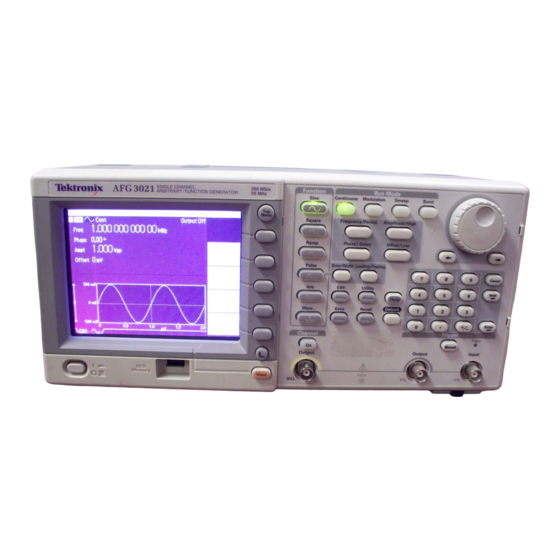
AFG3000 Series
Arbitrary/Function Generators
071-1640-04
Warning
The servicing instructions are for use by qualified
personnel only. To avoid personal injury, do not
perform any servicing unless you are qualified to
do so. Refer to all safety summaries prior to
performing service.
www.tektronix.com
Advertisement
Table of Contents
Troubleshooting

Related Manuals for Tektronix AFG3000 Series


Summary of Contents for Tektronix AFG3000 Series
- Page 1 Service Manual AFG3000 Series Arbitrary/Function Generators 071-1640-04 Warning The servicing instructions are for use by qualified personnel only. To avoid personal injury, do not perform any servicing unless you are qualified to do so. Refer to all safety summaries prior to performing service.
- Page 2 Commercial Computer Software - Restricted Rights clause at FAR 52.227-19, as applicable. Tektronix products are covered by U.S. and foreign patents, issued and pending. Information in this publication supercedes that in all previously published material. Specifications and price change privileges reserved.
- Page 3 Tektronix, shipping charges prepaid, and with a copy of customer proof of purchase. Tektronix shall pay for the return of the product to Customer if the shipment is to a location within the country in which the Tektronix service center is located. Customer shall be responsible for paying all shipping charges, duties, taxes, and any other charges for products returned to any other locations.
-
Page 5: Table Of Contents
Tektronix Service Offerings........ - Page 6 Fan..............6-18 AFG3000 Series Arbitrary/Function Generators Service Manual...
- Page 7 Using the Replaceable Parts List ......... AFG3000 Series Arbitrary/Function Generators Service Manual...
- Page 8 Table 6-4: Error codes ..........6-30 AFG3000 Series Arbitrary/Function Generators Service Manual...
- Page 9 List of Figures Figure 1-1: AFG3000 Series dimensions ....... .
- Page 10 Figure 8-2: Rear modules ..........8-10 AFG3000 Series Arbitrary/Function Generators Service Manual...
-
Page 11: General Safety Summary
Do Not Operate in Wet/Damp Conditions. Do Not Operate in an Explosive Atmosphere. Keep Product Surfaces Clean and Dry. Provide Proper Ventilation. Refer to the manual’s installation instructions for details on installing the product so it has proper ventilation. AFG3000 Series Arbitrary/Function Generators Service Manual... - Page 12 CAUTION indicates a hazard to property including the product. Symbols on the Product. The following symbols may appear on the product: WARNING Protective Ground CAUTION Double High Voltage (Earth) Terminal Refer to Manual Insulated viii AFG3000 Series Arbitrary/Function Generators Service Manual...
-
Page 13: Service Safety Summary
Use Care When Servicing With Power On. Dangerous voltages or currents may exist in this product. Disconnect power, remove battery (if applicable), and disconnect test leads before removing protective panels, soldering, or replacing components. To avoid electric shock, do not touch exposed connections. AFG3000 Series Arbitrary/Function Generators Service Manual... - Page 14 Service Safety Summary AFG3000 Series Arbitrary/Function Generators Service Manual...
-
Page 15: Environmental Considerations
European Union's requirements according to Directive 2002/96/EC on waste electrical and electronic equipment (WEEE). For information about recycling options, check the Support/Service section of the Tektronix Web site (www.tektronix.com). Mercury Notification. This product uses an LCD backlight lamp that contains mercury. - Page 16 Environmental Considerations AFG3000 Series Arbitrary/Function Generators Service Manual...
-
Page 17: Preface
This manual provides instructions to verify the performance of, calibrate, troubleshoot, and repair the arbitrary/function generators to the module level. Unless noted otherwise, the term “AFG3000 Series” refers to the models in the AFG3011, AFG3021B, AFG3022B, AFG3101, AFG3102, AFG3251, and AFG3252 arbitrary/function generators. -
Page 18: Finding Other Information
This manual mainly focuses on the performance verification, troubleshooting and maintenance of the arbitrary/function generator. See the following list for other documents supporting the arbitrary/function generator. All documents except Built-in Help are on the AFG3000 Series Product Documents CD-ROM that shipped with instrument. Document name... -
Page 19: Introduction
12 months. In addition, a performance check is recommended after module replacement. If the AFG3000 Series does not meet performance criteria, repair is necessary. Strategy for Servicing Throughout this manual, the term, module, refers to any field-replaceable component, assembly, or part of the arbitrary/function generator. -
Page 20: Tektronix Service Offerings
Introduction Tektronix Service Offerings Tektronix provides service to cover repair under warranty as well as other services that may provide a cost-effective answer to your service needs. Tektronix service technicians are well trained to service the arbitrary/function generator. They have access to the latest information on improvements to the AFG3000 Series as well as new options. -
Page 21: Specifications
Specifications... -
Page 23: Performance Conditions
Specifications These specifications apply to all AFG3000 Series Arbitrary/Function Generators. All specifications are guaranteed unless labeled “typical”. Typical specifications are provided for your convenience but are not guaranteed. Specifications that are check marked with the ✔ symbol are checked directly (or indirectly) in the Performance Verification section. -
Page 24: Table 1-2: Waveforms
1 μHz to 120 MHz AFG3251, AFG3252 Pulse AFG3011 1 mHz to 5 MHz AFG3021B, AFG3022B 1 mHz to 12.5 MHz AFG3101, AFG3102 1 mHz to 50 MHz AFG3251, AFG3252 1 mHz to 120 MHz AFG3000 Series Arbitrary/Function Generators Service Manual... - Page 25 AFG3101/AFG3102, 1 μHz to 50 MHz AFG3251/AFG3252, 1 μHz to 120 MHz Triggered/Gated Burst mode: AFG3011, 1 mHz to 2.5 MHz AFG3021B/AFG3022B, 1 mHz to 6.25 MHz AFG3101/AFG3102, 1 mHz to 25 MHz AFG3251/AFG3252, 1 mHz to 60 MHz AFG3000 Series Arbitrary/Function Generators Service Manual...
-
Page 26: Table 1-4: Phase (Except Dc, Noise, And Pulse)
50 Ω, 100 mV AFG3251/AFG3252 (frequency range: >200 MHz to 240 MHz): 50 mV to 4 V to 8 V into open circuit load dBm is used only for sine waveform. AFG3000 Series Arbitrary/Function Generators Service Manual... -
Page 27: Table 1-7: Dc Offset
AFG3251/AFG3252: Add 2.0 mV per °C for operation outside the range of 20 °C to 30 °C. Table 1-8: Internal noise add Characteristics Description Range 0% to 50% of amplitude setting (V ) of signal waveform Resolution AFG3000 Series Arbitrary/Function Generators Service Manual... -
Page 28: Table 1-9: Output Characteristics
5 MHz ≤ frq < 25 MHz:< –37 dBc 25 MHz ≤ frq ≤ 240 MHz: < –30 dBc 10 Hz to 20 kHz: < 0.2% ✔Total harmonic distortion page 4-30 (at 1 V amplitude) AFG3000 Series Arbitrary/Function Generators Service Manual... - Page 29 ≤ 50 ns AFG3011 ≤ 18 ns AFG3021B, AFG3022B ≤ 5 ns AFG3101, AFG3102 ≤ 2.5 ns AFG3251, AFG3252 Jitter (rms), typical AFG3021B, AFG3022B, 500 ps AFG3011 AFG3101, AFG3102 200 ps AFG3251, AFG3252 100 ps AFG3000 Series Arbitrary/Function Generators Service Manual...
- Page 30 ≤ 0.15% of peak output at 10% to 90% of amplitude range AFG3101, AFG3102 Symmetry 0% to 100% Arbitrary Rise time/fall time, typical ≤ 80 ns AFG3011 ≤ 20 ns AFG3021B, AFG3022B ≤ 8 ns AFG3101, AFG3102 ≤ 3 ns AFG3251, AFG3252 AFG3000 Series Arbitrary/Function Generators Service Manual...
-
Page 31: Table 1-10: Modulation
Internal modulating 2 mHz to 50.00 kHz frequency Peak deviation AFG3011 DC to 5 MHz AFG3021B, AFG3022B DC to 12.5 MHz AFG3101, AFG3102 DC to 50 MHz AFG3251, AFG3252 DC to 120 MHz AFG3000 Series Arbitrary/Function Generators Service Manual... - Page 32 The maximum waveform length for Arb is 2,048. Waveform data points over 2,048 are ignored. Pulse, DC, and Noise waveforms are not available. Start and stop frequencies depend on the waveform shape. Total sweep time = Sweep time + Hold time + Return time ≤ 300 s 1-10 AFG3000 Series Arbitrary/Function Generators Service Manual...
-
Page 33: Inputs/Outputs
100 ns minimum Impedance 10 kΩ Slope Positive/negative, selectable Trigger delay 0.0 ns to 85.000 s Resolution: 100 ps or 5 digits Burst: < 500 ps (trigger input to signal output) Jitter (rms), typical AFG3000 Series Arbitrary/Function Generators Service Manual 1-11... -
Page 34: General
4000 points waveform data GPIB: 42 ms USB: 20 ms LAN: 84 ms < 50 dBA Acoustic noise, typical Weight (approximate) 4.5 kg Dimensions See Figure 1-1 and Figure 1-2 on page 1-17 1-12 AFG3000 Series Arbitrary/Function Generators Service Manual... -
Page 35: Table 1-14: Power
Operating –30 °C to +70 °C Non operating Humidity At or below +40 °C: ≤ 80% Operating > +40 °C to +50 °C: ≤ 60% Altitude Operating Up to 3,000 meters (10,000 feet) AFG3000 Series Arbitrary/Function Generators Service Manual 1-13... -
Page 36: Certifications And Compliances
To ensure compliance with the EMC standards listed here, high quality shielded interface cables should be used. High quality shielded cables typically are braid and foil types that have low impedance connections to shielded connectors at both ends. 1-14 AFG3000 Series Arbitrary/Function Generators Service Manual... - Page 37 Pollution Degree 2. Normally only dry, nonconductive pollution occurs. Occasionally a temporary conductivity that is caused by condensation must be expected. This location is a typical office/home environment. Temporary condensation occurs only when the product is out of service. AFG3000 Series Arbitrary/Function Generators Service Manual 1-15...
- Page 38 Measurement Category II. For measurements performed on circuits directly connected to the low-voltage installation. Measurement Category I. For measurements performed on circuits not directly connected to MAINS. Overvoltage Category Overvoltage Category II (as defined in IEC 61010-1) 1-16 AFG3000 Series Arbitrary/Function Generators Service Manual...
-
Page 39: Figure 1-1: Afg3000 Series Dimensions
Figure 1-1: AFG3000 Series dimensions 482.6 44.4 (19.00) (1.75) 154.3 465.5 (6.08) (18.32) 37.3 37.3 (1.47) (1.47) 25.4 (1.00) 101.6 (4.00) 101.6 176.2 (4.00) (6.94) Front 36.8 (1.45) Figure 1-2: RM3100 Rackmount dimensions AFG3000 Series Arbitrary/Function Generators Service Manual 1-17... - Page 40 Specifications 1-18 AFG3000 Series Arbitrary/Function Generators Service Manual...
-
Page 41: Operating Information
Operating Information... -
Page 43: Operating Basics
GPIB Three functions integrated into one generator 10 MHz to 240 MHz Function Generator 5 MHz to 120 MHz Pulse Generator 14 bits Arbitrary Waveform Generator Ground isolation Synchronous operation USB flash drive interface AFG3000 Series Arbitrary/Function Generators Service Manual... -
Page 44: Installation
To ensure proper cooling, keep both sides of the instrument clear of CAUTION. obstructions. Power Supply Requirements Source Voltage and Frequency 100 V to 240 V, 47 Hz to 63 Hz or 115 V, 360 Hz to 440 Hz Power Consumption Less than 120 W AFG3000 Series Arbitrary/Function Generators Service Manual... -
Page 45: Protect Your Instrument From Misuse
When the instrument is used by students or other inexperienced users, always attach the fuse adapter to the output connectors to avoid damage. Tektronix part numbers for the fuse adapter are as follows: Adapter (P/N: 013-0345-00) 0.125 A fuse (P/N: 159-0454-00 (3 each)) -
Page 46: Floating Ground
When a potential voltage exists between the chassis ground and common ground, a short circuit from output to ground causes the instrument internal fuse to open and the output is stopped. If the fuse opens, you need to contact your local Tektronix Service Support. -
Page 47: Protect Your Dut
You cannot enter any values greater than 50 mV for High level. NOTE. When you set limit values using Output Menu, a level indicator is displayed at left end of graph area. Refer to Screen Interface on page 2-10 for the level indicator. AFG3000 Series Arbitrary/Function Generators Service Manual... -
Page 48: Powering The Instrument On And Off
Phase Delay Offset/Low Pulse Duty/Width Leading/Trailing Edit Utility Help More... Save Recall Default Channel Trigger Trigger Output Output Output Input Memory Memory View 1. Use the front-panel power button to power off the instrument. AFG3000 Series Arbitrary/Function Generators Service Manual... -
Page 49: Self Test And Self Calibration
Before executing self calibration, ensure that the ambient temperature is NOTE. between +20 °C and +30 °C (+68 °F to +86 °F). Allow a 20 minute warm-up period prior to executing self calibration. AFG3000 Series Arbitrary/Function Generators Service Manual... -
Page 50: Getting Acquainted With Your Instrument
Channel Trigger Trigger Output Output Output Input Memory Memory View Trigger Input connector View button Trigger Output connector USB connector Menu buttons Power On/Off switch CH1 and CH2 Output connectors Figure 2-5: Front-panel controls AFG3000 Series Arbitrary/Function Generators Service Manual... -
Page 51: Figure 2-6: Rear Panel
EXT REF INPUT. This input is used when synchronizing multiple arbitrary/function generators or an arbitrary/function generator and another device. EXT REF OUTPUT. When you want to synchronize multiple AFG3000 series arbitrary/function generators, or synchronize your arbitrary/function generator and another instrument, use the external reference output connector. (Except AFG3021B and AFG3022B) ADD INPUT. -
Page 52: Screen Interface
2. Shows the range of high limit and low limit set by the user. 3. Shows the amplitude level that is currently selected. Use the front-panel power button to power off the instrument. 2-10 AFG3000 Series Arbitrary/Function Generators Service Manual... -
Page 53: Theory Of Operation
Theory of Operation... -
Page 55: Overview
Theory of Operation This section describes the electrical operation of the AFG3000 Series Arbitrary/Function Generators to the module level. It describes the basic operation of each functional circuit block shown in Figure 3-1. The descriptions for the one and two channel units, and the color and monochrome units are slightly different. -
Page 56: Figure 3-1: Afg3000 Series Block Diagram
Theory of Operation Figure 3-1: AFG3000 Series block diagram AFG3000 Series Arbitrary/Function Generators Service Manual... -
Page 57: Platform
CPU board. BNC Insulator Board These boards insulate the I/O signal from the chassis. The A81 board is used for (A81/ A82) the rear-panel connectors and the A82 board is used for the front-panel connectors. AFG3000 Series Arbitrary/Function Generators Service Manual... -
Page 58: Generator Section
Calibration Circuit: DC Calibration of the output signal is done by a 16 bit AD Converter. Generator with Amp Board The A31/A32/A41/A42 boards are the same as the A11/A12 boards except they (A31/A32/A41/A42) have a different Output Amplifier board. AFG3000 Series Arbitrary/Function Generators Service Manual... - Page 59 Theory of Operation Output Amp Board Output Amplifier: Amplifying the output of the pre-amplifier with the DC offset. (A51/A61) Output Filter: LPF is used when a sine wave is output. AFG3000 Series Arbitrary/Function Generators Service Manual...
- Page 60 Theory of Operation AFG3000 Series Arbitrary/Function Generators Service Manual...
-
Page 61: Performance Verification
Performance Verification... -
Page 63: Self Tests
Self Tests and Performance Tests. You may not need to perform all of these procedures, depending on what you want to accomplish. To quickly confirm that the AFG3000 Series Arbitrary/Function Generators are operating properly, complete the Self Tests which begin on page 4-1. - Page 64 When an error is detected during calibration execution, the instrument displays an error code. Error codes are described in Error Codes on page 6-30. 4. Press any front-panel button to exit the diagnostics. AFG3000 Series Arbitrary/Function Generators Service Manual...
-
Page 65: Performance Tests
The Performance Tests include functional tests, such as the interface functional test, in this manual. The Functional Tests verify the functions; they verify that the AFG3000 Series Arbitrary/Function Generators features operate. They do not verify that they operate within limits. -
Page 66: Table 4-2: Test Equipment
10. Adapter Dual-Banana BNC (female) to dual banana Tektronix part number Signal interconnection to a Plug 103-0090-00 11. Adapter BNC(fe)-N(ma) BNC (female) to N (male) Tektronix part number Signal interconnection to a 103-0045-00 Spectrum Analyzer AFG3000 Series Arbitrary/Function Generators Service Manual... -
Page 67: Test Record
Performance Verification Test Record Photocopy this test record and use to record the performance test results for your AFG3000 Series Arbitrary/Function Generators. Excel spreadsheet Test record with embedded calculation formulas is also available in standard accessory document CD P/N 063-3828-xx. - Page 68 (800.0 × CF – 8.35) mVrms (800.0 × CF + 8.35) mVrms 800.0 mVrms at 1.00 kHz (1.500 × CF – 0.0154) Vrms (1.500 × CF + 0.0154) Vrms 1.500 Vrms at 1.00 kHz AFG3000 Series Arbitrary/Function Generators Service Manual...
- Page 69 (+2.500 × CF – 0.030) Vdc (+2.500 × CF + 0.030) Vdc +2.500 Vdc 0.000 Vdc –0.005 Vdc +0.005 Vdc (–2.500 × CF – 0.030) Vdc (–2.500 × CF + 0.030) Vdc –2.500 Vdc AFG3000 Series Arbitrary/Function Generators Service Manual...
- Page 70 Frequency 5.00 MHz Reference – 0.30 dB dB Reference + 0.30 dB Frequency 15.00 MHz Reference – 0.30 dB dB Reference + 0.30 dB Frequency 25.00 MHz Reference – 0.50 dB dB Reference + 0.50 dB AFG3000 Series Arbitrary/Function Generators Service Manual...
- Page 71 Frequency 100.0 MHz Reference – 1.00 dB dB Reference + 1.00 dB Frequency 150.00 MHz Reference – 1.00 dB dB Reference + 1.00 dB Frequency 240.0 MHz Reference – 2.00 dB dB Reference + 2.00 dB AFG3000 Series Arbitrary/Function Generators Service Manual...
- Page 72 Reference – 1.00 dB dB Reference + 1.00 dB Frequency 150.00 MHz Reference – 1.00 dB dB Reference + 1.00 dB Frequency 250.0 MHz Reference – 2.00 dB dB Reference + 2.00 dB 4-10 AFG3000 Series Arbitrary/Function Generators Service Manual...
- Page 73 4 MHz 5 MHz CH1 Harmonic Distortion reading – reference 0 dBc dBc Nth – reference < –50 dBc CH2 Harmonic Distortion reading – reference 0 dBc dBc Nth – reference < –50 dBc AFG3000 Series Arbitrary/Function Generators Service Manual 4-11...
- Page 74 200 MHz 300 MHz 400 MHz 500 MHz CH1 Harmonic Distortion reading – reference 0 dBc dBc Nth – reference < –37 dBc CH2 Harmonic Distortion reading – reference 0 dBc dBc Nth – reference < –37 dBc 4-12 AFG3000 Series Arbitrary/Function Generators Service Manual...
- Page 75 480 MHz 720 MHz 960 MHz 1.20 GHz CH1 Harmonic Distortion reading – reference 0 dBc dBc Nth – reference < –30 dBc CH2 Harmonic Distortion reading – reference 0 dBc dBc Nth – reference < –30 dBc AFG3000 Series Arbitrary/Function Generators Service Manual 4-13...
- Page 76 - reference (A – A ) (dBc) Bn/20 = 10 Limit < 0.2% ∑ ---------------------- - reading (dBm) reading - reference (An – A1) (dBc) Bn/20 = 10 Limit < 0.2% ∑ ---------------------- - 4-14 AFG3000 Series Arbitrary/Function Generators Service Manual...
- Page 77 20 kHz / < –50 dBc 300 MHz 600 MHz 20 kHz Sine 25.00 MHz 10 MHz / 20 MHz / 20 kHz / < –50 dBc 300 MHz 600 MHz 20 kHz AFG3000 Series Arbitrary/Function Generators Service Manual 4-15...
- Page 78 10 MHz 20 MHz 20 kHz < –44 dBc 300 MHz 600 MHz 20 kHz Sine 100.00 MHz 10 MHz 20 MHz 20 kHz < –38 dBc 300 MHz 600 MHz 20 kHz 4-16 AFG3000 Series Arbitrary/Function Generators Service Manual...
- Page 79 10 MHz 20 MHz 20 kHz < –29 dBc 300 MHz 600 MHz 20 kHz Sine 240.00 MHz 10 MHz 20 MHz 20 kHz < –28 dBc 300 MHz 600 MHz 20 kHz AFG3000 Series Arbitrary/Function Generators Service Manual 4-17...
- Page 80 Fall Time Amplitude: 1.0 V - - - - - 5 ns Rise Time Amplitude: 10.0 V - - - - - 5 ns Fall Time Amplitude: 10.0 V - - - - - 5 ns 4-18 AFG3000 Series Arbitrary/Function Generators Service Manual...
- Page 81 Fall Time Amplitude: 1.0 V - - - - - 2.5 ns Rise Time Amplitude: 5.0 V - - - - - 2.5 ns Fall Time Amplitude: 5.0 V - - - - - 2.5 ns AFG3000 Series Arbitrary/Function Generators Service Manual 4-19...
-
Page 82: Frequency/Period Test
5. Set up the arbitrary/function generator using the following steps: Select menu Setting Operation Function Pulse Pulse (front) 6. Check that reading of the frequency counter is between 0.999999 MHz and 1.000001 MHz. 4-20 AFG3000 Series Arbitrary/Function Generators Service Manual... -
Page 83: Amplitude Test
Be sure to connect the 50 Ω terminator to the arbitrary/function generator Output connector side. AFG3000 series BNC-Dual banana adapter CH1 Output 50 Ω BNC coaxial cable + 50 Ω terminator Figure 4-3: Amplitude tests AFG3000 Series Arbitrary/Function Generators Service Manual 4-21... - Page 84 (2.000 × CF ± 0.0204) Vrms Sine 1.000 kHz 2.000 Vrms Vrms (2.500 × CF ± 0.0254) Vrms Sine 1.000 kHz 2.500 Vrms Vrms (3.500 × CF ± 0.0354) Vrms Sine 1.000 kHz 3.500 Vrms Vrms 4-22 AFG3000 Series Arbitrary/Function Generators Service Manual...
-
Page 85: Dc Offset Test
CF (Calibration Factor) = 2 / (1 + 50 Ω / Measurement Ω) Measurement (reading of the DMM) Ω Examples 50.50 Ω 1.0050 (= 2 / (1 + 50 / 50.50)) 49.62 Ω 0.9962 (= 2 / (1 + 50 / 49.62)) AFG3000 Series Arbitrary/Function Generators Service Manual 4-23... -
Page 86: Figure 4-5: Dc Offset Tests
5. Verify that each offset measurement is within the range specified in the following tables. AFG3011 Measurement Range Function Offset (5.000 × CF ± 0.110) Vdc + 5.000 Vdc 0.000 Vdc ± 0.010 Vdc (– 5.000 × CF ± 0.110) Vdc – 5.000 Vdc 4-24 AFG3000 Series Arbitrary/Function Generators Service Manual... - Page 87 (2.500 × CF ± 0.030) Vdc + 2.500 Vdc 0.000 Vdc ± 0.005 Vdc (– 2.500 × CF ± 0.030) Vdc – 2.500 Vdc 6. (AFG3xx2 only) Repeat steps 3 through 5 for the channel 2 output. AFG3000 Series Arbitrary/Function Generators Service Manual 4-25...
-
Page 88: Ac Flatness Test
+ 4.0 dBm 500.00 kHz Reference ± 0.15 Sine + 4.0 dBm 1.00 MHz Reference ± 0.15 Sine + 4.0 dBm 5.00 MHz Reference ± 0.30 Sine + 4.0 dBm 10.00 MHz Reference ± 0.30 4-26 AFG3000 Series Arbitrary/Function Generators Service Manual... - Page 89 Reference ± 1.00 Sine + 4.0 dBm 150.00 MHz Reference ± 1.00 Sine + 4.0 dBm 240.00 MHz Reference ± 2.00 6. (AFG3xx2 only) Repeat steps 3 through 5 for the channel 2 output. AFG3000 Series Arbitrary/Function Generators Service Manual 4-27...
-
Page 90: Harmonics Distortion Test
Reference value in step 4. 7. Verify that the differences between the reference level and the signal level in the frequency of higher-order at each frequency are below the limit specified in the following tables. 4-28 AFG3000 Series Arbitrary/Function Generators Service Manual... - Page 91 100 MHz 200 MHz 300 MHz 400 MHz 500 MHz < –30 dBc 240 MHz 625 MHz 1.25 GHz 100 kHz 240 MHz 480 MHz 720 MHz 960 MHz 1.20 GHz < –30 dBc AFG3000 Series Arbitrary/Function Generators Service Manual 4-29...
-
Page 92: Total Harmonic Distortion Test
500 Hz 4. Set the Ref Level of the spectrum analyzer to 8 dBm. 5. When the THD cannot be measured directly, it is obtained by using the following calculation: ∑ ---------------------- - 4-30 AFG3000 Series Arbitrary/Function Generators Service Manual... - Page 93 62dBm or less, the calculation of NOTE. – THD can be skipped because it is THD<0.2%. 8. Verify that the THD is less than 0.2%. 9. (AFG3xx2 only) Repeat steps 2 through 8 for the channel 2 output. AFG3000 Series Arbitrary/Function Generators Service Manual 4-31...
-
Page 94: Spurious Test
7. Measure the maximum spurious level other than harmonic distortion of 1 V sine wave in each frequency. 8. Verify that the spurious signal at each frequency is equal to or less than the limit specified in the following tables. 4-32 AFG3000 Series Arbitrary/Function Generators Service Manual... - Page 95 50.00 MHz 10 MHz 20 MHz 20 kHz < –44 dBc 300 MHz 600 MHz 20 kHz 100.00 MHz 10 MHz 20 MHz 20 kHz < –38 dBc 300 MHz 600 MHz 20 kHz AFG3000 Series Arbitrary/Function Generators Service Manual 4-33...
- Page 96 200.00 MHz 10 MHz 20 MHz 20 kHz < –29 dBc 300 MHz 600 MHz 20 kHz 240.00 MHz 10 MHz 20 MHz 20 kHz < –28 dBc 300 MHz 600 MHz 20 kHz 4-34 AFG3000 Series Arbitrary/Function Generators Service Manual...
-
Page 97: Rise-Fall Time Test
Amplitude 1.0 Vpp Amplitude/High (front) Offset 0.0 V TopMenu > Offset/Low (front) Channel 1 Output On On (front) 3. Set up the Oscilloscope so the square waveform of 5 division amplitude is displayed. AFG3000 Series Arbitrary/Function Generators Service Manual 4-35... - Page 98 1.0 V 200 mV/div 1 ns/div ≤ 2.5 ns Square 10.00 MHz 0.0 V 5.0 V 1.0 V/div 1 ns/div 5. (AFG3xx2 only) Repeat steps 2 through 4 for the channel 2 output. 4-36 AFG3000 Series Arbitrary/Function Generators Service Manual...
-
Page 99: Adjustment Procedures
Adjustment Procedures... -
Page 101: Purpose
Table 5-1: Adjustments performed after repair Adjustment AFG3011 AFG3021B, AFG3022B AFG3101, AFG3102, AFG3251, AFG3252 A72 CPU A72 CPU A11, A12 A72 CPU A31, A32, A41, A51, A61 Output Generator Generator A42 Generator Reference Clock Flatness Spurious Trigger Delay AFG3000 Series Arbitrary/Function Generators Service Manual... -
Page 102: Equipment Required
Adapter Dual-Banana BNC (female) to dual banana Tektronix part number Signal interconnection to a 103-0090-00 Plug 10. Adapter BNC(fe)-N(ma) BNC (female) to N (male) Tektronix part number Signal interconnection to a 103-0045-00 Spectrum Analyzer AFG3000 Series Arbitrary/Function Generators Service Manual... -
Page 103: Performance Conditions
The adjustments in this section are an extensive, valid confirmation of performance and functionality when the following requirements are met: The cabinet covers must be on the AFG3000 Series. The instrument must have been calibrated/adjusted at an ambient temperature °... -
Page 104: Reference Clock
5. Adjust the Ref Clock value with the rotary knob so that the frequency counter reading is between 0.999999 MHz and 1.000001 MHz. 6. Push the Save menu button to save the adjusted value. AFG3000 Series Arbitrary/Function Generators Service Manual... -
Page 105: Lf Adjustment
Sine 100.00000 kHz CH1: (CH2: 5. Set the AFG3000 Series frequency to 100.000 Hz. 6. Push the Utility > -more- > -more- > Service Menu > Manual Calibration > LF Adjustment > (CH1) buttons. LF Adj value is selected. AFG3000 Series Arbitrary/Function Generators Service Manual... -
Page 106: Flatness Adjustment
7. Adjust the LF Adj value with the rotary knob so that the DMM voltage reading is the same as shown in the Table at step 4. 8. (AFG3102, AFG3252 only) Connect the AFG3000 Series CH2 Output to the DMM. Repeat steps 2 through 7 for the channel 2 output. - Page 107 9. Push the CH1-Flatness Apply Parameters button to enable the input data for flatness correction. 10. (AFG3xx2 only) Repeat steps 2 through 9 for the channel 2 output. 11. Push the button and Save menu button to save the adjusted value. AFG3000 Series Arbitrary/Function Generators Service Manual...
-
Page 108: Spurious Adjustment
Push the Utility > -more- > -more- > Service Menu > Manual Calibration > Spurious Adjustment > CH1 Sine 0.1 MHz buttons. 4. Set up the spectrum analyzer according to the Spurious adjust setup of the AFG3000 Series. AFG3000 Series Arbitrary/Function Generators Service Manual... - Page 109 Sine (Pulse) x.x MHz. 10. (AFG3xx2 only) Repeat steps 2 through 9 for the channel 2 output. 11. Push the button and the Save menu button to save the adjusted value. AFG3000 Series Arbitrary/Function Generators Service Manual...
-
Page 110: Trigger Delay Adjustment
Delay (front) Run Mode (CH2) Burst Burst (front) Trigger Delay 0.0 ns more (menu) > Delay Run Mode (CH2) Continuous Continuous (front) Channel 1 Output On On (front) Channel 2 Output On On (front) 5-10 AFG3000 Series Arbitrary/Function Generators Service Manual... - Page 111 19. Push the Continuous button to change the CH1 Run mode to Continuous mode. 20. Push the Phase | Delay >Recover Lead Delay buttons. 21. Check that the skew time of the two signals on the oscilloscope screen is less than 1 ns. AFG3000 Series Arbitrary/Function Generators Service Manual 5-11...
-
Page 112: Setting The Serial Number
4. Enter the MAC address with numeric keys and Function buttons. NOTE. Use the Function buttons to enter alphabetical characters. The Sine to More... button corresponds to A through F. Use the +/– key to enter the hyphen. 5. Push the OK button. 5-12 AFG3000 Series Arbitrary/Function Generators Service Manual... -
Page 113: Maintenance
Maintenance... -
Page 115: Preparation
6-2. These precautions will help you avoid damaging internal modules and their components due to electrostatic discharge (ESD). Static discharge can damage any semiconductor component in this CAUTION. arbitrary/function generator. AFG3000 Series Arbitrary/Function Generators Service Manual... -
Page 116: Inspection And Cleaning
The front and rear cases help keep dust out of the arbitrary/function generator and must be in place during normal operation. To avoid damage to the arbitrary/function generator, do not expose them to any sprays, liquids, or solvents. AFG3000 Series Arbitrary/Function Generators Service Manual... -
Page 117: Table 6-1: External Inspection Check List
Avoid the use of chemical cleaning agents which might damage the CAUTION. plastics used in this AFG3000 Series arbitrary/function generator. Use only deionized water when cleaning the front-panel buttons. Use an ethyl alcohol solution as a cleaner and rinse with deionized water. -
Page 118: Table 6-2: Internal Inspection Check List
To access the inside of the arbitrary/function generator for inspection and cleaning, refer to the Removal and Installation Procedures in this section. Inspect the internal portions of the AFG3000 Series arbitrary/function generator for damage and wear, using Table 6-2 as a guide. Defects should be repaired immediately. - Page 119 (75% solution) and rinse with warm deionized water. (A cotton-tipped applicator is useful for cleaning in narrow spaces and on circuit boards.) If steps 1 and 2 do not remove all the dust or dirt, please contact Tektronix. NOTE.
- Page 120 Maintenance AFG3000 Series Arbitrary/Function Generators Service Manual...
-
Page 121: Removal And Installation Procedures
List of Modules The Replaceable Parts List section provides a list of all replaceable modules. Any electrical or mechanical module, assembly, or part listed in the parts list is referred to as a module. AFG3000 Series Arbitrary/Function Generators Service Manual... -
Page 122: Summary Of Procedures
BNC bracket A72 CPU board Figure 6-1: Disassembly order Tools Required Use the following tools to remove and replace all modules: Torque-limiting screwdriver, long shank, 8 lb-in (0.85 N m) range with Torx T-15 tip AFG3000 Series Arbitrary/Function Generators Service Manual... -
Page 123: Flip Feet
2. Hold the flip foot with the smooth side facing down. 3. Gently squeeze the foot so that the hinge on one side fits into the slot, and twist slightly to snap into the slot on the other side. AFG3000 Series Arbitrary/Function Generators Service Manual... -
Page 124: Front-Panel Knob
Before you reinstall the rear case, reattach the front feet to the front case. Confirm that they are in place before reassembling the case. Remember to attach the chassis ground screw. 6-10 AFG3000 Series Arbitrary/Function Generators Service Manual... -
Page 125: Figure 6-4: Pasting The Urethane Foam Gaskets
2.0 mm to 2.5 mm from the edge of the case to ensure good contact with chassis ground. 348-1849-00 348-1849-00 1 mm 348-1848-00 348-1850-00 1 mm 2.0 to 2.5 mm Gasket Rear case Figure 6-4: Pasting the urethane foam gaskets AFG3000 Series Arbitrary/Function Generators Service Manual 6-11... -
Page 126: Top Cover
1. Remove the front-panel knob by firmly grasping the knob and pulling it away from the front panel. 2. Remove the four tapping screws attaching the front case to the main chassis. 3. The front case and the rubber switch can be removed together. 6-12 AFG3000 Series Arbitrary/Function Generators Service Manual... -
Page 127: A75 Front-Panel Board
2. Remove the seven screws attaching the A75 front-panel board to the main chassis. 3. Disconnect the front-panel board cable. Front panel board cable Figure 6-7: A75 front-panel board removal Installation. To install, reverse this procedure. AFG3000 Series Arbitrary/Function Generators Service Manual 6-13... -
Page 128: Display Module
J170 (CH1; from J390, CH2; from J790) on the output board. 2. Remove the two screws attaching the output module to the rear sub-panel. 3. Gently pull out the output board toward the rear according to the guide. 6-14 AFG3000 Series Arbitrary/Function Generators Service Manual... -
Page 129: Separation Of Rear Module And Main Chassis
The add-in cable at J370 from the ADD Input connector 2. Remove the three screws attaching the CPU board to the main chassis. 3. Remove the two screws near the air outlet attaching the rear module and main chassis. AFG3000 Series Arbitrary/Function Generators Service Manual 6-15... -
Page 130: Figure 6-10: Separation Of The Rear Module And Main Chassis
4. Use the flat-blade screwdriver to loosen the rear module and main chassis. 5. Pull out the rear module toward the rear. Figure 6-11: Pull out the rear module Installation. To install, reverse this procedure. 6-16 AFG3000 Series Arbitrary/Function Generators Service Manual... -
Page 131: Inverter
Inverter-bracket align with the two holes on the Inverter board. 3. Use the pliers to bend the two Inverter-bracket tabs into place and secure the Inverter board. hole hook Inverter bracket tabs hole Figure 6-13: Inverter installation AFG3000 Series Arbitrary/Function Generators Service Manual 6-17... -
Page 132: Fan
2. Align the fan with the fan-bracket. Align the fan so that air blows out the side of the chassis, not into the chassis. 3. Use the pliers to bend the two fan-bracket tabs into place and secure the fan. 6-18 AFG3000 Series Arbitrary/Function Generators Service Manual... -
Page 133: Power Supply
2. Disconnect the three cable connectors at J866, J862, and J900. 3. Remove the four screws attaching the power supply module and the insulator to the rear sub-panel. Figure 6-15: Power supply removal installation. To install, reverse this procedure. AFG3000 Series Arbitrary/Function Generators Service Manual 6-19... -
Page 134: A72 Cpu Board
Nut and spring washer Figure 6-16: Remove the BNC connectors 5. Disconnect the AC input cable at J860 on the CPU board. 6. Disconnect the A75 Key Board cable at J300 on the CPU board. 6-20 AFG3000 Series Arbitrary/Function Generators Service Manual... -
Page 135: A82 Bnc Insulator Board
3. Remove the three screws that attach the A82 BNC Insulator board to the rear sub-panel. 4. Remove the A82 BNC Insulator board from the rear sub-panel. Installation. To install, reverse this procedure. AFG3000 Series Arbitrary/Function Generators Service Manual 6-21... -
Page 136: Generator Board
2. Remove the two screws attaching the Generator board to main chassis from the bottom side. 3. Remove the Generator board from the main chassis. Figure 6-18: Generator board removal Installation. To install, reverse this procedure. 6-22 AFG3000 Series Arbitrary/Function Generators Service Manual... -
Page 137: A81 Bnc Insulator Board, Bnc Bracket
3. Remove the three screws that attach the A81 BNC Insulator board to the Generator board. 4. Remove the A81 BNC Insulator board and BNC bracket. Figure 6-19: A81 BNC Insulator board and BNC bracket removal Installation. To install, reverse this procedure. AFG3000 Series Arbitrary/Function Generators Service Manual 6-23... - Page 138 Removal and Installation Procedures 6-24 AFG3000 Series Arbitrary/Function Generators Service Manual...
-
Page 139: Troubleshooting
To prevent electrical shock, do not touch the heat sink of the power WARNING. supply assembly. There are potentially dangerous voltages present on the heat sink of the power supply assembly. AFG3000 Series Arbitrary/Function Generators Service Manual 6-25... -
Page 140: Figure 6-20: Platform Troubleshooting Procedure
Inverter. Replace the LCD module. Do USB, GPIB, and Replace the CPU board. LAN function normally? Completed a platform check Figure 6-20: Platform troubleshooting procedure 6-26 AFG3000 Series Arbitrary/Function Generators Service Manual... -
Page 141: Figure 6-21: Generator Troubleshooting Procedure
Ext Modulation Input, Replace the Generator board. Ext Ref Input, and Ext Ref Output function? Does Replace the Amplifier board. the Add Input function? Completed a Generator check Figure 6-21: Generator troubleshooting procedure AFG3000 Series Arbitrary/Function Generators Service Manual 6-27... -
Page 142: Diagnostics
If you see such a message, press the OK button to proceed with the next step. The AFG3000 Series software starts. When the AFG3000 Series contains an unresolved error, the test cannot be conducted normally. -
Page 143: Calibration
4. Press any front panel button to exit from the diagnostics. Do not turn off the power while executing calibration. If the power is turned NOTE. off while calibration, data stored in internal nonvolatile memory may be lost. AFG3000 Series Arbitrary/Function Generators Service Manual 6-29... -
Page 144: Error Codes
CH2 ASIC TINT calibration failure A12/A32/A42/A51/A61 1403 CH1 ASIC SGEN calibration failure A1x/A3x/A4x/A51/A61 1404 CH2 ASIC SGEN calibration failure A12/A32/A42/A51/A61 1405 CH1 ASIC clock duty calibration failure A1x/A3x/A4x/A51/A61 1406 CH2 ASIC clock duty calibration failure A12/A32/A42/A51/A61 6-30 AFG3000 Series Arbitrary/Function Generators Service Manual... - Page 145 CH2 x20dB 2 attenuator failure A12/A32/A42 2411 CH1 Filter failure A51/A61 2412 CH2 Filter failure A51/A61 2413 CH1 x20dB 3 attenuator failure 2501 CH1 Sine Flatness failure A1x/A3x/A4x/A51/A61 2502 CH2 Sine Flatness failure A12/A32/A42/A51/A61 AFG3000 Series Arbitrary/Function Generators Service Manual 6-31...
- Page 146 Troubleshooting 6-32 AFG3000 Series Arbitrary/Function Generators Service Manual...
-
Page 147: Diagrams
Diagrams... -
Page 149: Figure 7-1: Interconnection For Afg3011
Diagrams Figure 7-1, Figure 7-2, and Figure 7-3 show the AFG3000 Series module interconnections. These diagrams show how the modules in the arbitrary/function generator connect together. Figure 7-1: Interconnection for AFG3011 AFG3000 Series Arbitrary/Function Generators Service Manual... -
Page 150: Figure 7-2: Interconnection For Afg302Xb
Diagrams Figure 7-2: Interconnection for AFG302xB AFG3000 Series Arbitrary/Function Generators Service Manual... -
Page 151: Figure 7-3: Interconnection For Afg310X And Afg325X
Diagrams Figure 7-3: Interconnection for AFG310x and AFG325x AFG3000 Series Arbitrary/Function Generators Service Manual... - Page 152 Diagrams AFG3000 Series Arbitrary/Function Generators Service Manual...
-
Page 153: Replaceable Parts List
Replaceable Parts List... -
Page 155: Parts Ordering Information
Replaceable Parts List This section contains a list of the replaceable modules for the AFG3000 Series Arbitrary/Function Generators. Use this list to identify and order replacement parts. Parts Ordering Information Replacement parts are available through your local Tektronix field office or representative. -
Page 156: Using The Replaceable Parts List
Description Figure & index number Items in this section are referenced by component number. Tektronix part number Use this part number when ordering replacement parts from Tektronix. Model This indicates the model that uses this item. 4 and 5 Serial number Column three indicates the serial number at which the part was first effective. - Page 157 AFG3021B, AFG3022B, AFG3011 CASE, REAR; PC/ABS, PLASTIC BLEND, TEK BLUE, SAFETY CONTROLLED 202-0435-01 AFG3101, AFG3102, AFG3251, CASE, REAR; 202041100 W/METALIZED, SAFETY CONTROLLED AFG3252 367-0538-00 AFG3021B, AFG3022B, AFG3101, HANDLE, CARRYING; OVERMOLDED AFG3102, AFG3251, AFG3252, AFG3011 AFG3000 Series Arbitrary/Function Generators Service Manual...
- Page 158 AFG3252 211-1143-00 AFG3021B, AFG3022B, AFG3101, SCREW,PT; K35-1.57,PAN HEAD,T-15 AFG3102, AFG3251, AFG3252, AFG3011 260-2791-00 AFG3021B, AFG3022B, AFG3101, ENCODER, DIGITAL; 24 CPR, 24 DETENTS, INCREMENTAL, AFG3102, AFG3251, AFG3252, QUADRATURE OUTPUT AFG3011 346-0299-00 AFG3251, AFG3252 BAND; BAND,PA AFG3000 Series Arbitrary/Function Generators Service Manual...
- Page 159 MARKER,IDENT; LABEL,FRONT PANEL,6.100 X 3.800,0.015 POLYCARBONATE,JAPANESE 335-1292-01 MARKER,IDENT; LABEL,FRONT PANEL,6.100 X 3.800,0.015 POLYCARBONATE,SIMPLE CHINESE 335-1293-01 MARKER,IDENT; LABEL,FRONT PANEL,6.100 X 3.800,0.015 POLYCARBONATE,TRADITIONAL CHINESE 335-1294-01 MARKER,IDENT; LABEL,FRONT PANEL,6.100 X 3.800,0.015 POLYCARBONATE,KOREAN 335-1539-00 MARKER,IDENT; LABEL,FRONT PANEL,6.100 X 3.800,0.015 POLYCARBONATE,RUSSIAN AFG3000 Series Arbitrary/Function Generators Service Manual...
- Page 160 MARKER, IDENT; LABEL, MKD AFG3011, 0.010 PC FILM, LEXAN, W/ADHESIVE BACK, SAFETY CONTROLLED 174-5150-00 AFG3021B CA ASSY, SP; DATA, MONO, 7.0 L 174-4673-00 AFG3022B, AFG3101, AFG3102, CA ASSY, SP; DATA, COLOR, 7.0 L AFG3251, AFG3252, AFG3011 AFG3000 Series Arbitrary/Function Generators Service Manual...
-
Page 161: Figure 8-1: Exploded Diagram
Replaceable Parts List (includes 20, 21 and 22) See Figure 8-2 on page 8-10. Figure 8-1: Exploded diagram AFG3000 Series Arbitrary/Function Generators Service Manual... - Page 162 DEEP,ELECTROLESS NICKEL PLATE AFG3011 220-0265-00 AFG3021B, AFG3011 NUT,PLAIN,HEX; 0.5-28 X 0.625 HEX,BRS CD PL 220-0265-00 AFG3022B, AFG3101, AFG3251 NUT,PLAIN,HEX; 0.5-28 X 0.625 HEX,BRS CD PL 220-0265-00 AFG3102, AFG3252 NUT,PLAIN,HEX; 0.5-28 X 0.625 HEX,BRS CD PL AFG3000 Series Arbitrary/Function Generators Service Manual...
- Page 163 MOUNT,CLIP; WIRE ROUTING CLIP,NYLON 6/6,ADHESIVE BACKING, AFG3102, AFG3251, AFG3252, NATURAL COLOR AFG3011 119-5489-00 AFG3021B, AFG3022B, AFG3101, EMI SUPPRESSION; FERRITE,ROUND CABLE;50 OHM AT 10-100MHZ, AFG3102, AFG3251, AFG3252, 100 OHM AT 100-500MHZ;SNAP ON,0.39 ID X 1.3 LEN X 0.83 OD AFG3011 AFG3000 Series Arbitrary/Function Generators Service Manual...
-
Page 164: Figure 8-2: Rear Modules
Replaceable Parts List (includes 31) Figure 8-2: Rear modules 8-10 AFG3000 Series Arbitrary/Function Generators Service Manual...
Need help?
Do you have a question about the AFG3000 Series and is the answer not in the manual?
Questions and answers