
Related Manuals for Smartgen HGM8140D


Summary of Contents for Smartgen HGM8140D
- Page 1 HGM8140 GENSET CONTROLLER USER MANUAL HGM8140D DISPLAY MODULE HGM8140M HOST MODULE SMARTGEN (ZHENGZHOU) TECHNOLOGY CO., LTD.
- Page 2 SmartGen Technology at the address above. Any reference to trademarked product names used within this publication is owned by their respective companies. SmartGen Technology reserves the right to change the contents of this document without prior notice. Table 1 Software Version Date...
-
Page 3: Table Of Contents
5.4 SHUTDOWN ALARMS ........................16 6 WIRINGS CONNECTION ........................19 6.1 HGM8140M MILITARY GENSET CONTROLLER PANNEL ............19 6.2 HGM8140D MLITARY GENSET CONTROLLER BACK PANEL ........... 22 7 SCOPS AND DEFINITIONS OF PROGRAMMABLE PARAMETERS ..........23 7.1 CONTENTS AND SCOPES OF PARAMETERS ................23 7.2 USER-DEFINED PERIOD OUTPUT .................... - Page 4 HGM8140 MILITARY GENSET CONTROLLER USER MANUAL 13.14 PERKINS ............................ 51 13.15 SCANIA ............................52 13.16 VOLVO EDC3 ..........................52 13.17 VOLVO EDC4 ..........................53 13.18 VOLVO-EMS2 ..........................53 13.19 YUCHAI ............................54 13.20 WEICHAI ............................ 54 14 ETHERNETINTERFACE ........................55 14.1 NETWORK CLIENT MODE ......................
-
Page 5: Overview
HGM8140 MILITARY GENSET CONTROLLER USER MANUAL 1 OVERVIEW HGM8140 military genset controller, integrated digitization, intelligentization, and networking technology, adopts “Main Control and Display “separated type mode. It is suitable for single unit automation and monitoring system to achieve automatic start/stop, data measurement, alarm protection as well as remote control, remote measurement and remote communication functions. -
Page 6: Performance And Characteristics
HGM8140 D can be set as RS232 port display module or CAN port display module via front panel keys operation. HGM8140 D module also be set as enabled/disabled control, if it is able to control, HGM8140M can be controlled by HGM8140D, otherwise, HGM8140D without remote control function. - Page 7 HGM8140 MILITARY GENSET CONTROLLER USER MANUAL Accumulate total generator power kWh For generator, controller has over and under voltage, over and under frequency, over current and over power detection functions. Precision measure and display parameters about Engine. Temp. (WT) °...
-
Page 8: Specification Operation
Flexible Relay Output 3 5A DC28V power supply output Flexible Relay Output 4 5A AC 250V volt free output Flexible Relay Output 5 5A AC250V volt free output HGM8140D:136mm x110mmx41mm(panel-mount) Case Dimensions HGM8140M:150mmx104mmx41 mm(mounted in a cabinet) Panel Cutout HGM8140D:121mmx93mm CT Secondary Current... -
Page 9: Operation
HGM8140 MILITARY GENSET CONTROLLER USER MANUAL 4 OPERATION 4.1 KEY FUNCTION Table 3 Button Description Icons Keys Description Stop running generator in Auto/Manual mode; Reset alarms when genset in alarming status; Lamp test (press at least 3 seconds) in stop mode; During stopping process, press this button again to stop generator Stop/Reset immediately;... -
Page 10: Controller Panel
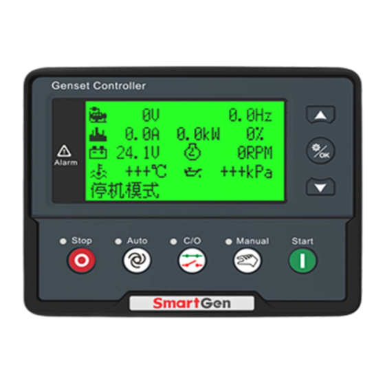
HGM8140 MILITARY GENSET CONTROLLER USER MANUAL 4.2 CONTROLLER PANEL Fig. 1 HGM8140D Front Panel NOTE: Part of indicator lights illustration: Alarm Indicators: slowly flash when warn alarms; fast flash when shutdown alarms; light is off when no alarms. 4.3 LCD DISPLAY There are three display interfaces: default interface;... -
Page 11: Auto Start/Stop Operation
HGM8140 MILITARY GENSET CONTROLLER USER MANUAL Fig. 2 Gen Page Example Fig. 3 Load Page Example 4.4 AUTO START/STOP OPERATION Press , its indicator lights, and controller enters Auto mode. Starting Sequence, HGM8140: Generator enters into “start delay” as soon as “Remote Start” input is active or DC input volt is below pre-set start volt. -
Page 12: Manual Start/Stop Operation
HGM8140 MILITARY GENSET CONTROLLER USER MANUAL Enter “generator at rest” as soon as “after stop time” is over. If genset fail to stop, controller will initiate alarms (fail to stop warning shown on LCD). 4.5 MANUAL START/STOP OPERATION HGM8140: Manual mode is selected by pressing the button;... -
Page 13: Protection
HGM8140 MILITARY GENSET CONTROLLER USER MANUAL 5 PROTECTION 5.1 WARNINGS When controllers detects the warning signals, alarm only and not stop the genset, besides, the LCD displays the warning information. Table 4 Controller Warning Alarms Type Description When the controller detects that the engine speed is 0 and the delay is Loss Of Speed 0, it will initiate a warning alarm and the corresponding alarm Signal... - Page 14 HGM8140 MILITARY GENSET CONTROLLER USER MANUAL Type Description When it is enabled and the controller detects that config. sensor temperature (sensor type: temperature sensor) has exceeded the High Temperature pre-set value, it will initiate a warning alarm and the corresponding alarm information will be displayed on LCD.
-
Page 15: Trip Alarm
HGM8140 MILITARY GENSET CONTROLLER USER MANUAL Type Description warning Input oil pressure of input port shutdown is prohibited, controller will initiate a warning alarm and the corresponding alarm information will be displayed on LCD. Gen Over Volt When controller detects genset voltage is higher than the pre-set Warning warning value, it will issue warning signal. -
Page 16: Trip And Stop Alarms
HGM8140 MILITARY GENSET CONTROLLER USER MANUAL 5.3 TRIP AND STOP ALARMS When controller detects shutdown alarm, it will send signal to open breaker and shuts down generator, and alarms type will be displayed on the LCD. Table 6 Controller Trip & Stop Alarms Type Description When the controller detects that the genset current has exceeded the... - Page 17 HGM8140 MILITARY GENSET CONTROLLER USER MANUAL Type Description When controller detects the voltage value is higher than the set value, it Gen Over Voltage will send stop signals and the corresponding alarm information will be displayed on LCD. When controller detects the frequency value is lower than the set value, Gen Under Voltage it will send stop signals and the corresponding alarm information will be displayed on LCD.
- Page 18 HGM8140 MILITARY GENSET CONTROLLER USER MANUAL Type Description When controller detects the power value (power is positive) is higher than the max. set value and the action select “shutdown”, it will send Over Power stop signals. When controller detects the reverse power value (power is negative) is higher than the max.
-
Page 19: Wirings Connection
HGM8140 MILITARY GENSET CONTROLLER USER MANUAL 6 WIRINGS CONNECTION 6.1 HGM8140M MILITARY GENSET CONTROLLER PANNEL Fig.4 HGM8140M Controller Rear Panel Table 8 Terminal Wiring Connection Description Function Cable Size Remarks 2.5mm Connected with negative of starter battery Connected with positive of starter battery. If wire 2.5mm length is over 30m, better to double wires in parallel. - Page 20 GND connected; Short connect Terminal 26 and 28 and connect to 120Ω terminal resistor. A(+) 0.5mm 0.5mm RS232 0.5mm Connect with HGM8140D host monitoring module 0.5mm Relay Output COM 2.5mm Relay normally open, volt Aux. Relay Output 4 2.5mm free, rated 16A, volt free output.
- Page 21 HGM8140 MILITARY GENSET CONTROLLER USER MANUAL Function Cable Size Remarks monitoring input of genset (2A fuse recommended). Connected to V-phase output Genset V-phase voltage 1.0mm of genset (2A fuse monitoring input recommended). Connected to W-phase output Genset W-phase voltage 1.0mm of genset (2A fuse monitoring input recommended).
-
Page 22: Hgm8140D Mlitary Genset Controller Back Panel
HGM8140 MILITARY GENSET CONTROLLER USER MANUAL 6.2 HGM8140D MLITARY GENSET CONTROLLER BACK PANEL Fig. 5 Terminal Wiring Connection Description Table 9 Terminal Wiring Description Function Cable Size Remarks 2.5mm Connected with negative of starter battery Connected with positive of starter battery. If wire 2.5mm... -
Page 23: Scops And Definitions Of Programmable Parameters
HGM8140 MILITARY GENSET CONTROLLER USER MANUAL 7 SCOPS AND DEFINITIONS OF PROGRAMMABLE PARAMETERS 7.1 CONTENTS AND SCOPES OF PARAMETERS Table 10 Parameters Settings and Scope Items Parameters Defaults Description Time from mains abnormal or remote start Start Delay (0~3600)s signal is active to start genset. Time from mains normal or remote start Stop Delay (0~3600)s... - Page 24 HGM8140 MILITARY GENSET CONTROLLER USER MANUAL Items Parameters Defaults Description set value and the “Gen abnormal delay” has Shutdown expired, Gen Over Voltage Shutdown alarm is active. When set the value as 620V, the controller does not detect over voltage signal.
- Page 25 HGM8140 MILITARY GENSET CONTROLLER USER MANUAL Items Parameters Defaults Description Signal shutdown the generator. During generator is normal running, when Charge Alternator alternator D+(WL) voltage has fallen below (0-30)V Failure the set value and remains for 5s, It will initiate a shutdown alarm signal. When battery voltage has exceeds the set Battery Over...
- Page 26 HGM8140 MILITARY GENSET CONTROLLER USER MANUAL Items Parameters Defaults Description Factory default: Low Oil Pressure Warning Digital Input 2 (0-26) Input, details to see Table 12. Digital Input (0-20.0)s Delay Factory default: Remote Start Input, details Digital Input 3 (0-26)s to see Table 12.
- Page 27 HGM8140 MILITARY GENSET CONTROLLER USER MANUAL Items Parameters Defaults Description Disconnect When generator frequency higher than the (10-30)Hz Frequency set value, starter will be disconnected. Disconnect Engine When generator oil pressure higher than the (0-400)kPa Oil Pressure set value, starter will be disconnected. High Temp.
- Page 28 HGM8140 MILITARY GENSET CONTROLLER USER MANUAL Items Parameters Defaults Description 0: Disenable 1:Enable Boot Screen (0-1) Boot Interface delay can be adjusted Maintenance Password to enter into the maintenance (0-9999) Password setting page. Controller‟s date setting Date Setting 0 Custom temperature sensor 1 Custom pressure sensor 2 Custom level sensor Custom...
- Page 29 HGM8140 MILITARY GENSET CONTROLLER USER MANUAL Items Parameters Defaults Description Warning lasts for 5s, under voltage is considered and under volt warning is initiated. When it is set to 30V, under voltage signal is not detected. When gen freq is higher than this and last Over Freq.
- Page 30 HGM8140 MILITARY GENSET CONTROLLER USER MANUAL Item Description Close when the generator enters into Stop Idle delay/ Energized to Speed Drop Relay Stop delay (close time: Stop Idle delay). Action when genset is normal running while deactivated when Run Output engine speed is lower than the “crank disconnect speed”.
- Page 31 HGM8140 MILITARY GENSET CONTROLLER USER MANUAL Item Description Custom Period 4 Custom Period 5 Custom Period 6 Custom Combined 1 Custom Combined 2 Custom Combined 3 Custom Combined 4 Custom Combined 5 Custom Combined 6 Reserved Reserved Reserved Reserved Reserved Reserved Reserved It is controlled by cooler of temperature sensor‟s limited threshold.
- Page 32 HGM8140 MILITARY GENSET CONTROLLER USER MANUAL Item Description Reserved Over Freq Warning Action when generator over frequency shutdown alarm. Shutdown Gen Over Volt Shutdown Action when generator over voltage shutdown. Under Freq Action when generator low frequency shutdown. Shutdown Under Volt. Shutdown Action when generator low voltage shutdown.
-
Page 33: User-Defined Period Output
HGM8140 MILITARY GENSET CONTROLLER USER MANUAL Item Description Reserved In Stop Mode Action when system is in stop mode. In Manual Mode Action when system is in Manual mode. Reserved Reserved Aux Input 1 Active Action when input port 1 is active Aux Input 2 Active Action when input port 2 is active Aux Input 3 Active... -
Page 34: User-Defined Combination Output
HGM8140 MILITARY GENSET CONTROLLER USER MANUAL 7.3 USER-DEFINED COMBINATION OUTPUT Defined combination output is composed by 3 parts, OR condition output SW1, OR condition output SW2, AND condition output SW3. SW1 or SW2 is TRUE, while SW3 is TRUE, Defined combination output is active; SW1 and SW2 are FALSE, or SW3 is FALSE, Defined combination output isdeactivated. - Page 35 HGM8140 MILITARY GENSET CONTROLLER USER MANUAL Table 12 Defined Contents of Digit Input Port 1~5 (All active for GND (B~) connected) Type Description Including following functions, Indication: indicate only, not warning or shutdown. Warning: warn only, not shutdown. Shutdown: alarm and shutdown immediately Trip and stop: alarm, generator unloads and shutdown after User Configured...
- Page 36 Instrument Mode RS232 Display Control When it is active, hose control function can be realized by the Enable displayed HGM8140D module on RS232 port. CAN-1 Display Control When it is active, hose control function can be realized by the Enable displayed HGM8140D module on CAN-1 port.
- Page 37 HGM8140 MILITARY GENSET CONTROLLER USER MANUAL Table 13 Sensors Selection Item Content Remark 0 Not used 1 Custom Resistor Curve 2 VDO 3 SGH 4 SGD 5 CURTIS Defined resistance‟s range is Temperature Sensor 6 DATCON 0Ω-6000Ω, default is SGX sensor. 7 VOLVO-EC 8 SGX 9 Reserved...
- Page 38 HGM8140 MILITARY GENSET CONTROLLER USER MANUAL Table 14 Crank Disconnect Conditions Setting description Speed Gen frequency Speed + Gen frequency Speed +Oil pressure Gen frequency + Oil pressure Speed + Gen frequency + Oil pressure Oil pressure NOTES: There are 3 conditions to make starter separate with engine; speed, generator frequency and oil pressure can be used separately while oil pressure suggest be used together with speed and generator frequency.
-
Page 39: Parameters Setting
HGM8140 MILITARY GENSET CONTROLLER USER MANUAL 8 PARAMETERS SETTING Start the controller, then press to enter into the parameters setting menu, menu items as follows: Set Parameters Information Language Eventlog Maintennance Parameters Setting When entered password interface, inputting “0318” can set all parameter items in Table 10. If the password is changed, only input the password same as controllers‟, can the parameter be set via PC software. -
Page 40: Sensor Setting
HGM8140 MILITARY GENSET CONTROLLER USER MANUAL 9 SENSOR SETTING 1) When sensors are reselected, the sensor curve will be transferred into the standard value. For example, if temperature sensor is SGH (120° C resistor type), its sensor curve is SGH (120° C resistor type);... -
Page 41: Commissioning
ATS transfers to genset on load. If not, please check ATS controlling wiring connection according to this user manual; If there is any other question, please contact SmartGen‟s service. HGM8140 Military Genset Controller Version 1.2... -
Page 42: Typical Application
HGM8140 MILITARY GENSET CONTROLLER USER MANUAL 11 TYPICAL APPLICATION Fig.7 HGM8140M Typical Application Fig.8 HGM8140 Connection Schematic diagram HGM8140 Military Genset Controller Version 1.2 2019-09-12 Page 42 of 56... - Page 43 HGM8140 MILITARY GENSET CONTROLLER USER MANUAL Fig.9 Single Phase 2-Wire Wiring Connection Fig.10 2-Phase 3-Wire Connection NOTE: Expand relay with high capacity in start and fuel output is recommended. HGM8140 Military Genset Controller Version 1.2 2019-09-12 Page 43 of 56...
-
Page 44: Installation
NOTE: Care should be taken not to over tighten the screws of fixing clips. 12.2 OVERALL DIMENSION Fig.11 HGM8140D Overall and Cutout Dimensions Fig.12 HGM8140M Overall and Installation Dimensions HGM8140 military genset controller can suit for widely range of battery voltage (8~35) VDC. - Page 45 HGM8140 MILITARY GENSET CONTROLLER USER MANUAL Speed Sensor Input Speed sensor is the magnetic equipment which be installed in starter and for detecting teeth of flywheel. Its connection wires to controller should apply for 2 cores shielding line. The shielding layer should connect to No.
-
Page 46: Connections Of Controller With J1939 Engine
HGM8140 MILITARY GENSET CONTROLLER USER MANUAL 13 CONNECTIONS OF CONTROLLER WITH J1939 ENGINE 13.1 CUMMINS ISB/ISBE Table 16 Connector B Terminals of controller Connector B Remark Programmable relay output1 set as “Fuel Output” Relay Output1 Start relay output Connect with starter coil directly. Expand 30A relay, battery ECU power Set programmable relay output 2 as “ECU... -
Page 47: Cummins Qsm11(Import)
HGM8140 MILITARY GENSET CONTROLLER USER MANUAL 13.3 CUMMINS QSM11(import) Suitable for CM570 engine control module, engine type: QSM11 G1, QSM11 G2. Table 20 C1 Connector Terminals of controller C1 connector Remark Programmable relay output 1 set as “Fuel Output” Relay Output 1 5&8 and outside expand relay, when fuel output, making port 5 and port 8 of C1 be connected. -
Page 48: Cummins Gcs-Modbus
HGM8140 MILITARY GENSET CONTROLLER USER MANUAL 13.5 CUMMINS GCS-MODBUS It is suitable for GCS engine control module. RS485-MODBUS used to read information of engine. Engine types are QSX15, QST30, QSK23 / 45/60/78 and so on. Table 24 D-SUB Connector 06 Terminals of controller D-SUB connector 06 Remark... -
Page 49: Cummins Qsz13
HGM8140 MILITARY GENSET CONTROLLER USER MANUAL 13.7 CUMMINS QSZ13 Table 27 Engine OEM Connector Terminals of controller OEM connector of engine Remark Relay Output 1 Start relay output Connect to starter coil directly Setting to idle speed control, normally open output. Relay Output 2 16&41 Making 16 connect to 41 during high-speed... -
Page 50: Deutz Emr2
HGM8140 MILITARY GENSET CONTROLLER USER MANUAL 13.9 DEUTZ EMR2 Table 29 F Connector F connector Remark F connector Expand 30A relay, battery Configure relay output 1 as “Fuel Output” Relay Output 1 voltage of 14 is supplied by relay. Fuse is 16A. Start relay output Connect to starter coil directly. -
Page 51: Mtu Adec(Smart Module)
HGM8140 MILITARY GENSET CONTROLLER USER MANUAL 13.12 MTU ADEC(SMART MODULE) It is suitable for MTU engine with ADEC (ECU8) and SMART module. Table 32 ADEC (X1 Connector) Terminals of controller ADEC (X1port) Remark Configure relay output 1 as “Fuel Output”. X1 Relay Output 1 X1 10 Terminal 9 connected to negative of battery... -
Page 52: Scania
HGM8140 MILITARY GENSET CONTROLLER USER MANUAL 13.15 SCANIA It is suitable for S6 engine control module. Engine type is DC9, DC12, and DC16. Table 37 B1 Connector Terminals of controller B1 connector Remark Configure relay output 1 as “Fuel Output”. Relay Output 1 Start relay output Connect to starter coil directly. -
Page 53: Volvo Edc4
HGM8140 MILITARY GENSET CONTROLLER USER MANUAL 13.17 VOLVO EDC4 Suitable engine types: TD520, TAD520 (optional), TD720, TAD720 (optional), TAD721, TAD722, and TAD732. Table 40 Connector Terminals of controller Connector Remark Expanded 30A relay, and relay offers battery Configure relay output 1 as “Fuel Output”. Relay Output 1 voltage for terminal14. -
Page 54: Yuchai
Using impedance 120Ω connecting line. CAN(L) 1.34 Engine type: GTSC1 NOTE: If there is any question of connection between controller and ECU communication, please feel free to contact SmartGen‟s service. HGM8140 Military Genset Controller Version 1.2 2019-09-12 Page 54 of 56... -
Page 55: Ethernetinterface
The communication between the controller and monitoring equipment is carried out using TCP ModBus protocol. NOTE: In this connection mode controller parameters can be set. SmartGen provides testing software for this connection mode. Communication protocol can be obtained from the SmartGen service. -
Page 56: Troubleshooting
HGM8140 MILITARY GENSET CONTROLLER USER MANUAL 15 TROUBLESHOOTING Table 46 Troubleshooting Symptoms Possible Solutions Check starting batteries; Controller no response with Check controller connection wirings; power. Check DC fuse. Check the water/cylinder temperature is too high or not; Genset shutdown Check the genset AC voltage;...
Need help?
Do you have a question about the HGM8140D and is the answer not in the manual?
Questions and answers