Sign In
Upload
Download
Table of Contents
Contents
Add to my manuals
Delete from my manuals
Share
URL of this page:
HTML Link:
Bookmark this page
Add
Manual will be automatically added to "My Manuals"
Print this page
×
Bookmark added
×
Added to my manuals
Manuals
Brands
Tadiran Telecom Manuals
Network Hardware
FlexSet 280
Manual
Tadiran Telecom FlexSet 280 Manual
Hide thumbs
Also See for FlexSet 280
:
User manual
(233 pages)
1
2
Table Of Contents
3
4
5
6
7
8
9
10
11
12
13
14
15
16
17
18
19
20
21
22
23
24
25
26
27
28
29
30
31
32
33
34
35
36
37
38
39
40
41
42
43
44
45
46
47
48
49
50
51
52
53
54
55
56
57
58
59
60
61
62
63
64
65
66
67
68
69
70
71
72
73
74
75
76
77
78
79
80
81
82
83
84
85
86
87
88
89
90
91
92
93
94
95
96
97
98
99
100
101
102
103
104
105
106
107
108
109
110
111
112
113
114
115
116
117
118
119
120
121
122
123
124
125
126
127
128
129
130
131
132
page
of
132
Go
/
132
Contents
Table of Contents
Troubleshooting
Bookmarks
Table of Contents
Table of Contents
Related Documentation
Related Documentation for DKT/DST/DPEM Terminals
Related Documentation for Flexair/Coralair Wireless Terminals
Flexset Installation
Preparing for Installation
Inspect for Damage
Unpacking the Shipping Container
Peripheral Card Connections
Line Distances
Maximum Line Lengths with Internal or External Power Supply
Maximum Line Lengths
Space Requirements
Installing the Flexset
To Connect the Flexset to a Standard Wall Socket
Flexset 280/281 Bottom View
Handset and Twisted Cord
External Power Supply
Wall Mount or Desk Elevation Position
Database Programming
General System Parameters Applied to All Keysets in the System
Possible Group Assignments
Parameters Applied to each Keyset
Personalizing the Flexset
Placing the Telephone Number
Programming the Buttons
Handset Hook
Preparing the Blank Button Labels
Label Sheet Catalog
Printing the Multi-Designation Label
Flexset 280S and 281S Top Plate Removal
Flexset 280D and 280D-Z Top Plate Removal
Flexset 120S and 121S Top Plate Removal
Flexset 120D Top Plate Removal
Flexset Troubleshooting
Distinguishing the Various Keyset Versions
Keysets and Card Compatibility
Keysets & Card Compatibility
Flexset 121S and 281S Versus Coral Versions
Coral Version 15.5 or Higher
Coral Version 15 or Lower
Keyset Operation States
Initialization
Stand-Alone
On-Line Operation
Manual Test
Flexset Software Version
Key Test
Volume Button
Speaker Test
On-Line
Power Failure Mode
Early Versions of DKT/DST Phones with SFT Peripheral Cards
Flexset with SDT/SKD/SVD Peripheral Cards
Displays
10 Flexset Turn off after Initialization
Wall Mount/Desk Elevation
Wall Mount
Wall Mounting Bracket
Side View, Completed Wall Mounting Bracket
Side View, Completed Wall Mount
Handset Hook
Wall Mounting (Using Wall Socket)
Side View, Completed Wall Mounting Bracket (Using Wall Socket)
Desk Elevation Bracket (28 Degree)
Desktop Elevation Rubber Bumpers
Fitting the Desktop Elevation Bracket - Flexset 280X
Fitting the Desktop Elevation Bracket - Flexset 120X
Desk Elevation Stand (60 Degree)
Side View, Completed Elevating the Flexset (60O)
Flexset PEX-F, PEX-FS Installation
Overview
Preparing for Installation
Inspect for Damage
Unpacking the Shipping Container
Rear View of Flexset PEX (Installed)
Flexset PEX Module
Installing
To Install a PEX Module in an Existing Flexset 280/281 Unit
Flexset 280/281 Base with Plastic Cover
Flexset 280/281 Base with PEX/APA Connector Exposed
Flexset 280/281 Base with PEX Installation
Removing the PEX Module
External Power Supply
Handset and Additional (Listen Only) Handset
Flexset APA-F, APDL-FS Installation
Overview
Preparing for Installation
Inspect for Damage
Rear View of Flexset APA (Installed)
Unpacking the Shipping Container
Flexset APA Module
Installing
To Install an APA Module in an Existing Flexset 280S Unit
Flexset 280S Base with Plastic Cover
Flexset 280S Base with PEX/APA Connector Exposed
Flexset 280S/Flexapdl Base with APA Connected
Removing the APA Module
External Power Supply
Flexset APA External Connectors
Data Communication Connections
Program API Device Connection
RS-232E Programming Port
Connecting the APA to a PC
Database Programming
Parameters Applied to each Flexapdl and Flexset 280S with APA
General System Parameters Applied Equally to All Apas in the System
Flexset PEX/APA-F, PEX/APA-FS Installation
Overview
Preparing for Installation
Inspect for Damage
Unpacking the Shipping Container
Rear View of Flexset PEX/APA (Installed)
Flexset PEX/APA Module
Installing
To Install a PEX/APA Module in an Existing Flexset 280/281 Unit
Flexset 280/281 Base with Plastic Cover
Flexset 280/281 Base with PEX/APA Connector Exposed
Flexset 280/281 Base with PEX/APA Connected
Removing the PEX/APA Module
External Power Supply
Handset and Additional (Listen Only) Handset
Data Communication Connections
Database Programming
Flexset 40B Installation
Overview
Flexset 40B
Flexset 280S/281S with One Flexset 40Bs Attached
Flexset 280S/281S with Three Flexset 40Bs Attached
Turret Console (Coral Version 14.5 )
Pre-Installation Requirements
Preparing for Installation
Inspect for Damage
Unpacking the Shipping Container
Connections
Installation
Connecting a Flexset 40B to a Flexset 280/281
Connecting a Second Flexset 40B
Connecting a Third Flexset 40B
Connecting Fourth, Fifth and Sixth Flexset 40Bs
Coral Flexset 280 with Six Flexset 40Bs Attached, Bottom View
Disconnecting the Flexset 40B from the Flexset Telephone
External Power Supply (Mandatory)
Wall Mounting/Desk Elevation
System and Cards Resources
Peripheral Card Resources
Coral System Resources
Database Programming
General Parameters
Parameters Applied to each Flexset 280/281 with Flexset 40Bs
Parameters Relevant for Turret Console Applications
Programming Buttons
External Power Supply Installation
External Power Requirements
When to Use an External Power Supply
Single Unit Power Supply
Powering Multiple Units over the LAN
Flexapdl Installation
Overview
Preparing for Installation
Inspect for Damage
Unpacking the Shipping Container
Flexapdl Terminal
Peripheral Card Connections
Line Distances
Installing
To Connect the Flexapdl to a Standard Wall Socket
Wall Mount or Desk Elevation Position
Data Communication Connections
Program API Device Connection
RS-232E Programming Port
Connecting the Flexapdl to a PC
Database Programming
General System Parameters Applied to All Keysets in the System
Parameters Applied to each Flexapdl
General System Parameters Applied Equally to All Apas in the System
CPA Installation
Overview
Preparing for Installation
Inspect for Damage
Unpacking the Shipping Container
CPA Terminal
Peripheral Card Connections
Line Distances
Circuit Description
External Voice Paging (Public Address)
CPA Relay Special Considerations
Installing
To Connect the CPA to the Coral Via a Standard Wall Socket
To Connect the CPA to the External Speaker
To Connect the Relay Contacts
External Power Supply
Wall Mount Position
Volume Setup
Ring Setup
Database Setup
Database Programming
General System Parameters Applied to All Keysets in the System
Possible Group Assignments
Parameters Applied to each CPA
Specifications
Voip Terminals
Related Documentation for Voip Terminals
Advertisement
Quick Links
1
Table of Contents
2
Flexset Installation
3
Database Programming
4
Programming the Buttons
Download this manual
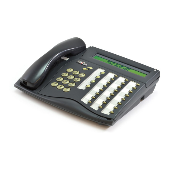
FlexSet
120,120D,120L,120S,121S
280,280D,280D-Z,280S,281S
FlexAPDL, PEX, APA and CPA
Digital Station
Terminal Equipment
Installation Manual
.
(Edition 4.1)
Creating a new world of IPportunities
Table of
Contents
Previous
Page
Next
Page
1
2
3
4
5
Advertisement
Table of Contents
Need help?
Do you have a question about the FlexSet 280 and is the answer not in the manual?
Ask a question
Questions and answers
Related Manuals for Tadiran Telecom FlexSet 280
IP Phone Tadiran Telecom FlexSet 280 User Manual
Tadiran telecom flexset digital voip terminal (233 pages)
IP Phone Tadiran Telecom FlexSet 280S User Manual
For coral ipx (253 pages)
Network Hardware Tadiran Telecom FlexSet 281S Manual
(132 pages)
Network Hardware Tadiran Telecom Coral FlexiCom 6000 Installation Procedure And Hardware Reference Manual
(340 pages)
This manual is also suitable for:
Flexset 280d
Flexset 280d-z
Flexset 280s
Flexset 281s
Flexset flexapdl
Flexset pex
...
Show all
Flexset apa
Flexset cpa
Table of Contents
Save PDF
Print
Rename the bookmark
Delete bookmark?
Delete from my manuals?
Login
Sign In
OR
Sign in with Facebook
Sign in with Google
Upload manual
Upload from disk
Upload from URL


Need help?
Do you have a question about the FlexSet 280 and is the answer not in the manual?
Questions and answers