Table of Contents
Advertisement
Quick Links
Advertisement
Table of Contents

Related Manuals for Kontron COMe-bID7


Summary of Contents for Kontron COMe-bID7
- Page 1 USER GUIDE COMe-bID7 User Guide Rev. 1.2 Doc. ID: 1069-1349...
- Page 2 COMe-bID7 User Guide Rev. 1.2 This page has been intentionally left blank...
-
Page 3: Disclaimer
In cases of doubt, please contact Kontron. This user guide is protected by copyright. All rights are reserved by Kontron. No part of this document may be reproduced, transmitted, transcribed, stored in a retrieval system, or translated into any language or computer language, in any form or by any means (electronic, mechanical, photocopying, recording, or otherwise), without the express written permission of Kontron. -
Page 4: Intended Use
SEVERE PHYSICAL OR ENVIRONMENTAL DAMAGE (COLLECTIVELY, "HIGH RISK APPLICATIONS"). You understand and agree that your use of Kontron devices as a component in High Risk Applications is entirely at your risk. To minimize the risks associated with your products and applications, you should provide adequate design and operating safeguards. -
Page 5: Revision History
If you have any difficulties using this user guide, discover an error, or just want to provide some feedback, contact Kontron support. Detail any errors you find. We will correct the errors or problems as soon as possible and post the revised user guide on our website. -
Page 6: Symbols
COMe-bID7 User Guide Rev. 1.2 Symbols The following symbols may be used in this manual DANGER indicates a hazardous situation which, if not avoided, will result in death or serious injury. WARNING indicates a hazardous situation which, if not avoided, could result in death or serious injury. -
Page 7: For Your Safety
Therefore, in the interest of your own safety and of the correct operation of your new Kontron product, you are requested to conform with the following guidelines. -
Page 8: Lithium Battery Precautions
General Instructions on Usage In order to maintain Kontron’s product warranty, this product must not be altered or modified in any way. Changes or modifications to the product, that are not explicitly approved by Kontron and described in this user guide or received from Kontron Support as a special handling instruction, will void your warranty. -
Page 9: Weee Compliance
Encourage separate collection and subsequent treatment, reuse, recovery, recycling and sound environmental disposal of EEE Improve the environmental performance of all those involved during the lifecycle of EEE Environmental protection is a high priority with Kontron. Kontron follows the WEEE directive You are encouraged to return our products for proper disposal. -
Page 10: Table Of Contents
3.8. SATA ..........................................26 3.9. Ethernet – 1G / 2.5GBASE-T LAN ................................ 26 3.10. Ethernet – 4x 10GBASE-KR ................................. 26 3.10.1. Overview of currently supported LAN Interfaces on COMe-bID7 ..................27 3.11. UART ........................................... 29 3.12. Additional Features ....................................29 3.13. - Page 11 COMe-bID7 User Guide Rev. 1.2 4.1. ACPI Suspend Modes and Resume Events ............................31 4.2. Real Time Clock (RTC) ..................................... 31 4.3. NVMe Storage (Option) ..................................31 4.4. Hardware Monitor (HWM) ..................................31 4.5. Trusted Platform Module (TPM) ................................. 31 4.6.
-
Page 12: List Of Tables
About Kontron ........................................95 List of Tables Table 1: Pin Assignment of Type 7 and COMe-bID7 ..........................15 Table 2: Commercial Grade Modules (0°C to 60°C operating)......................16 Table 3: Industrial Grade Modules by Design (E2, -40°C up to 85°C Operating) ................. 17 Table 4: Intel®... -
Page 13: List Of Figures
Figure 2: Bottom View of COMe-bID7 ................................ 18 Figure 3: Block Diagram COMe-bID7 ................................19 Figure 4: MTBF De-rating Values (Reliability report: COMe-bID7 E2 D-1747NTE EV) .............. 42 Figure 5: Module Dimensions ..................................43 Figure 6: Module Height ....................................44 Figure 7: Module Top and Bottom SODIMM Assembly (Option) ...................... -
Page 14: 1/ Introduction
1/ Introduction 1.1. Product Description Kontron's Computer-on-Module COMe-bID7 is a COM Express® BASIC TYPE 7 form-factor with Intel®’s Xeon® D- 1700 processor family. The Intel® Xeon ® D-1700 Generation increases efficiency and performance per watt ratio, which is a result of the innovative 10nm technology and has up to 10 cores for control, micro server, storage and communication applications in Internet of Things (IoT) and embedded environment. -
Page 15: Understanding Com Express® Functionality
1.3. Understanding COM Express® Functionality All Kontron COM Express® basic and compact modules contain two 220pin connectors; each of it has two rows called Row A & B on primary connector and Row C & D on secondary connector. The COM Express® Computer-On-Module (COM) features the following maximum amount of interfaces according to the PCI Industrial Computer Manufacturers Group (PICMG) module Pin-out type. -
Page 16: 2/ Product Specification
PICMG specification COM.0 Rev 3.1. The COMe-bID7 can also be offered compliant to COM-Express Spec Rev 3.0 on request. The COMe-bID7 is available in different variants to cover the individual demands in performance, price and power. 2.2. Commercial Grade Modules The following is a list of modules for commercial temperature range. -
Page 17: Industrial Grade Modules
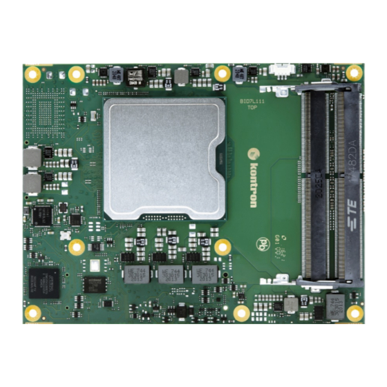
COM Express® basic pin-out type 7 COM.0 R3.1 with Intel® D-1715TER, 50 W, 4 core, 2.4 GHz, 4x 10GBASE-KR, 16x PCIe Gen4, 16x PCIe Gen3, 2x DDR4 SO-DIMM socket, industrial temperature 2.4. Product Views Figure 1: Top View of COMe-bID7 Fan Connector Processor 2x DDR4 SODIMM sockets Optional NVMe www.kontron.com... -
Page 18: Figure 2: Bottom View Of Come-Bid7
COMe-bID7 User Guide Rev. 1.2 Figure 2: Bottom View of COMe-bID7 XDP debug port (not populated on production units) Optional 2x DDR4 SODIMM sockets 2x COMe connectors www.kontron.com // 18... -
Page 19: 3/ Functional Specification
COMe-bID7 User Guide Rev. 1.2 3/ Functional Specification 3.1. Block Diagram COMe-bID7 Figure 3: Block Diagram COMe-bID7 www.kontron.com // 19... -
Page 20: Processors
COMe-bID7 User Guide Rev. 1.2 3.2. Processors The Intel® Xeon® processor D-1700 processor family with 45 mm x 45 mm package size (FCBGA) is the next generation System-on-Chip (SoC) with processor cores built using Intel 10-nanometer process technology. The three major complexes in this highly-integrated SoC are the CPU, PCH and NAC. -
Page 21: Com Express Compliance
#595914 3.3. COM Express Compliance The COMe-bID7 can be offered in two different versions regarding the compliance to the COM Express COM.0 specification Rev 3.0 or Rev 3.1. The main different between both is the support of PCIe Gen 4.0 and the pin definition for the 10G LAN interfaces... -
Page 22: Com.0 Rev 3.0: Available On Request (Legacy Mode)
COM.0 Rev 3.0: available on request (legacy mode) 10G LAN - “legacy” mode For selected 10GbE modes the required additional components are directly populated on the COMe-bID7 module. The legacy mode enables those components on the module, which allow using the COMe-bID7 module on carriers/backplanes designed according to the COM Express specification COM.0 Rev 3.0. -
Page 23: Pci Express 4.0
COMe-bID7 User Guide Rev. 1.2 3.5. PCI Express 4.0 The SoC CPU supports 16x PCIe Gen 4.0 lanes used to support COMe PCIe #16-31 with one Root Complex (RPC) and four Root Ports (RP) max. Table 7: SoC – PCI Express Gen. 4.0... -
Page 24: Table 8: Soc - Hsio Usage: Pci Express Gen 3.0, Sata, Usb, Onboard I/O
COMe-bID7 User Guide Rev. 1.2 Table 8: SoC – HSIO Usage: PCI Express Gen 3.0, SATA, USB, onboard I/O Module Function BOM Option Comment SoC HSIO Lane Port Configuration COMe PCIE #0 HSIO #0 COMe PCIE #1 HSIO #1 HSIO #18... -
Page 25: Usb
Please contact Kontron Support for other BIOS configurations. 3.7. USB USB 3.x ports are backwards compatible with the USB 2.0 specification. The COMe-bID7 allows a maximum of four USB 3.1 Gen 1 ports including four USB 2.0 ports. Table 10: Supported USB Features USB 3.1 Gen 1 Ports... -
Page 26: Sata
See Table 8: SoC – HSIO Usage: PCI Express Gen 3.0, SATA, USB, onboard I/O. 3.9. Ethernet – 1G / 2.5GBASE-T LAN The COMe-bID7 supports one 1 GbE/2.5 GbE Base-T Ethernet interface using the Intel® i225-LM Ethernet controller for commercial temperature grades and the Intel®I225-IT for industrial temperature grades (E2). -
Page 27: Overview Of Currently Supported Lan Interfaces On Come-Bid7
Typical chip to chip connection e.g. via backplane or via short direct attach cable COMe-bID7: LAN config LEK 7.6 Evaluation Platform: COMe Evaluation Carrier T7 (68300-0000-00-0) – Note: COMe-bID7 must be factory-preconfigured for COM.0 R3.0 regarding PCI Express support COMe Evaluation Carrier T7 Gen2 A2T7 (68301-0001-00-8) and expansion card ADA-COMe-T7-G2 4X 10G DAC (68301-0000-04-4) 10G-SFI (on request) –... - Page 28 COMe-bID7 User Guide Rev. 1.2 Please contact Kontron Support for further assistance. Please refer to the Application Note at EMD Customer Section (Customer Section | Kontron Europe and Asia. www.kontron.com // 28...
-
Page 29: Uart
Two serial RX/TX ports from the SOC (PCIe based, non-legacy, no RTS/CTS) with an option for two UART serial RX/TX ports alternatively from the Embedded Controller (available on request as custom version). 3.12. Additional Features Table 11: General, Special Kontron and Optional Features General Features 10G Ethernet PICMG COM.0 R3.1 compliance PCI Express PICMG COM.0 R3.1 compliance... -
Page 30: Evaluation Platforms For Come-Bid7 - Compatibility Matrix
COMe-bID7 User Guide Rev. 1.2 3.13. Evaluation platforms for COMe-bID7 – Compatibility Matrix Please see below the possible combinations regarding the COMe-bID7 configuration and the matching evaluation platform COMe-bID7 Evaluation Platform PCIe LAN Config and related LEK Carrier - PCIe Gen3 only... -
Page 31: 4/ Features And Interfaces
The COMe-bID7 supports typical RTC values of 3 V and less than 10 μA. When powered by the mains power supply on- module regulators generate the RTC voltage, to reduce RTC current draw. The RTC’s battery voltage range is 2.8 V to 3.47 V. -
Page 32: Onboard Fan Connector
The COMe-bID7 supports an independently programmable watchdog that works with two stages that can be used stage by stage. -
Page 33: Fast I2C
LPC, a zero delay clock buffer is required. This leads to limitations for ISA bus and SIO (standard I/O(s) like floppy or LPT interfaces) implementation. The COMe-bID7 LPC clock buffer allows for the connection of three LPC devices 4.12. -
Page 34: Spi Flash Update
SPI Flash device. If disconnecting and reconnecting the same module again, this step is not necessary. Register for Kontron’s Customer Section to get access to BIOS downloads and PCN service. 4.13. System Management Bus (SMB) The System Management Bus (SMB) is a simple 2-wire bus for low-speed system management communication. -
Page 35: Gpio
(e.g. 10 K ohms), or pull-down resistors with a lower resistance pull-up (e.g. 10 K ohms). 4.15. NS-CI The COMe-bID7 supports the NC-SI (Network Controller Sideband Interface) physical interface. The NC-SI signals from the D-1700 SOC are routed to the COMe connector. www.kontron.com... -
Page 36: 5/ Accessories
HSP COMe-bID7 (E2) through Heatspreader for COMe-bID7 (E2), with Cu-core, holes through holes 38025-0000-99- HSK COMe-basic active (w/o Active Cooler for COMe-bID7 to be mounted on 0C05 HSP) 38025-0000-99- HSK COMe-basic passive (w/o Passive Cooler for COMe-bID7 to be mounted on... -
Page 37: General Accessories
COMe-bID7 User Guide Rev. 1.2 5.2. General Accessories Table 20: General Accessories List Product Number Mounting Description 38017-0000-00-5 COMe Mount KIT 5mm 1set Mounting Kit for 1 module including screws for 5mm connectors 38017-0000-00-0 COMe Mount KIT 8mm 1set Mounting Kit for 1 module including screws for 8mm... -
Page 38: 6/ Electrical Specification
Maximum 100 mV peak to peak 0 – 20 MHz. 6.4. Power Consumption The COMe-bID7 supports D-1700 processor SKUs up to 90 W TDP. For Information on Detailed Power Consumption measurements in all states and benchmarks for CPU, Graphics and Memory performance, refer to the Application Note at EMD Customer Section (Customer Section | Kontron Europe and Asia). -
Page 39: Atx Mode
COMe-bID7 User Guide Rev. 1.2 6.5. ATX Mode By connecting an ATX power supply with VCC and 5VSB, PWR_OK is set to low level and VCC is off. Press the Power Button to enable the ATX PSU setting PWR_OK to high level and powering on VCC. The ATX PSU is controlled by the PS_ON# signal which is generated by SUS_S3# through inversion. -
Page 40: 7/ Power Control
7.1. Power Supply The COMe-bID7 supports a power input from 8.5 V to 20 V in the commercial grade version, but 12 V in the industrial version. The supply voltage is applied through the VCC pins (VCC) of the module connector. -
Page 41: 8/ Standards And Certification
COMe-bID7 User Guide Rev. 1.2 8/ Standards and Certification The COMe-bID7 complies with the listed European Council directives or the latest status thereof: European Council directive relating to Electromagnetic Compatibility (2014/30/EU) General Product safety Directive (2001/95/EC) Low Voltage directive (2014/35/EU) The following table provides information regarding standards that are elements of the CE declaration and additional standard compliancy information. -
Page 42: Mtbf
When the module is connected to external power, the only battery drain is from leakage paths. Figure 4 shows the MTBF de-rating value for the module variant when used in an office or telecommunications environment. Figure 4: MTBF De-rating Values (Reliability report: COMe-bID7 E2 D-1747NTE EV) www.kontron.com // 42... -
Page 43: 9/ Mechanical Specification
COMe-bID7 User Guide Rev. 1.2 9/ Mechanical Specification 9.1. Dimensions The dimensions of the module are 95.0 mm x 125.0 mm. Figure 5: Module Dimensions CAD drawings are available at EMD Customer Section. www.kontron.com // 43... -
Page 44: Height
13 mm +/- 0.65 mm 9.1.2. Module Height with Four SODIMM Memory Sockets The overall height of the module and carrier board depends on whether the COMe-bID7 is implemented with: two SODIMMs both located on module’s top side (standard variant) ... -
Page 45: Figure 7: Module Top And Bottom Sodimm Assembly (Option)
COMe-bID7 User Guide Rev. 1.2 Figure 7: Module Top and Bottom SODIMM Assembly (Option) Top View SODIMM Top Assembly Side View Bottom View SODIMM Bottom Assembly COMe Connector www.kontron.com // 45... -
Page 46: Thermal Management, Heatspreader And Cooling Solutions
9.2. Thermal Management, Heatspreader and Cooling Solutions A heatspreader plate assembly is available from Kontron for the COMe-bID7. The heatspreader plate on top of this assembly is NOT a heat sink. It works as a COM Express®-standard thermal interface to use with a heat sink or external cooling devices. -
Page 47: Heatspreader Dimensions
9.2.1. Heatspreader Dimensions The COMe-bID7 heatspreaders are built from aluminum with a copper core. The heatspreaders have threads or through holes for mounting and are black anodized. The devices are delivered single packed. The heatspreaders 68009-0000-99-0 and 68009-0000-99-1 can be used with Kontron’s active and passive cooling solutions 38025-0000-99-0C05 and 38025-0000-99-0C06. -
Page 48: 10/ Come Connector Pin-Out List
COMe-bID7 User Guide Rev. 1.2 COMe Connector Pin-out List Figure 10: COMe Connector with 220 pins This table lists the pins and signals according to the PICMG specification COM.0 Rev 3.1 and Rev 3.0 Type 7 standard. Figure 11: COMe Connector Pinout... -
Page 49: Table 27: Pin-Out List A
COMe-bID7 User Guide Rev. 1.2 Table 27: Pin-out List A Grey background for pins different between COM.0 R.0 and R3.1 Signal Description Type Termination / Comment Power Ground PWR GND GBE0_MDI3- Ethernet Media Dependent DP-I/O Interface 3 - GBE0_MDI3+ Ethernet Media Dependent... - Page 50 COMe-bID7 User Guide Rev. 1.2 Signal Description Type Termination / Comment PCIE_TX15- PCI Express Lane 15 Transmit DP-O AC Coupled on Module SUS_S5# Soft Off Indicator O-3.3 PCIE_TX14+ PCI Express Lane 14 DP-O AC Coupled on Module Transmit + PCIE_TX14-...
- Page 51 COMe-bID7 User Guide Rev. 1.2 Signal Description Type Termination / Comment PCIE_TX5- PCI Express Lane 5 Transmit DP-O AC Coupled on Module GPI0 General Purpose Input 0 I-3.3 PU 100k 3.3V (S0) PCIE_TX4+ PCI Express Lane 4 Transmit DP-O AC Coupled on Module...
- Page 52 COMe-bID7 User Guide Rev. 1.2 Signal Description Type Termination / Comment Power Ground PWR GND Power Ground PWR GND PCIE_TX11+ PCI Express Lane 11 Transmit DP-O AC Coupled on Module PCIE_TX11- PCI Express Lane 11 Transmit DP-O AC Coupled on Module...
-
Page 53: Table 28: Pin-Out List B
COMe-bID7 User Guide Rev. 1.2 Signal Description Type Termination / Comment A106 VCC_12V Main Input Voltage A107 VCC_12V Main Input Voltage A108 VCC_12V Main Input Voltage A109 VCC_12V Main Input Voltage A110 Power Ground PWR GND Table 28: Pin-out List B... - Page 54 COMe-bID7 User Guide Rev. 1.2 Signal Description Type Termination / Comment PWR_OK Power OK I-3.3 PU 51K (S5) via diode PCIE_TX14+ PCI Express Lane 14 Receive DP-I PCIE_TX14- PCI Express Lane 14 Receive DP-I Watch Dog Time-Out event O-3.3 PD 10K R3.0: RSVD...
- Page 55 COMe-bID7 User Guide Rev. 1.2 Signal Description Type Termination / Comment Power Ground PWR GND PCIE_RX5+ PCI Express Lane 5 Receive + DP-I PCIE_RX5- PCI Express Lane 5 Receive - DP-I GPO1 General Purpose Output 1 O-3.3 PD 100k PCIE_RX4+...
- Page 56 COMe-bID7 User Guide Rev. 1.2 Signal Description Type Termination / Comment VCC_5V_SBY 5V Standby PWR 5V (S5) optional (not necessary in single supply mode) VCC_5V_SBY 5V Standby PWR 5V (S5) optional (not necessary in single supply mode) VCC_5V_SBY 5V Standby...
-
Page 57: Table 29: Pin-Out List C
COMe-bID7 User Guide Rev. 1.2 Table 29: Pin-out List C Signal Description Type Termination / Comment Power Ground PWR GND Power Ground PWR GND USB_SSRX0- USB Super Speed Receive – DP-I USB_SSRX0+ USB Super Speed Receive + DP-I Power Ground... - Page 58 COMe-bID7 User Guide Rev. 1.2 Signal Description Type Termination / Comment 10G_KR_RX3+ 10GBASE-KR receive DP-I AC Coupled on Module differential pair + 10G_KR_RX3- 10GBASE-KR receive DP-I AC Coupled on Module differential pair - Power Ground PWR GND 10G_KR_RX2+ 10GBASE-KR receive...
- Page 59 COMe-bID7 User Guide Rev. 1.2 Signal Description Type Termination / Comment R3.0: Management I2C Clock for O/OD-3.3 PU 2k2 3.3V (S5) 10G_PHY_MDC_SCL1 external PHY R3.1: RSVD10G Not used R3.0: PU 2k2 3.3V (S5) 10G_PHY_MDC_SCL0 MDIO clock - for PHY setup O/OD-3.3...
- Page 60 COMe-bID7 User Guide Rev. 1.2 Signal Description Type Termination / Comment PCIE_RX21+ PCI Express Lane 21 Receive DP-I PCIE_RX21- PCI Express Lane 21 Receive DP-I Power Ground PWR GND PCIE_RX22+ PCI Express Lane 22 Receive DP-I PCIE_RX22- PCI Express Lane 22 Receive...
-
Page 61: Table 30: Pin-Out List D
COMe-bID7 User Guide Rev. 1.2 Signal Description Type Termination / Comment PCIE_RX29+ PCI Express Lane 29 Receive DP-I PCIE_RX29- PCI Express Lane 29 Receive DP-I Power Ground PWR GND RSVD Reserved for future use PCIE_RX30+ PCI Express Lane 30 Receive... - Page 62 COMe-bID7 User Guide Rev. 1.2 Signal Description Type Termination / Comment USB_SSTX2+ USB Super Speed Transmit + DP-O Power Ground PWR GND USB_SSTX3- USB Super Speed Transmit – DP-O USB_SSTX3+ USB Super Speed Transmit + DP-O Power Ground PWR GND R3.0:...
- Page 63 COMe-bID7 User Guide Rev. 1.2 Signal Description Type Termination / Comment R3.0: 10G_PHY_CAP_23 PHY on ports 2 and 3 mode I-3.3 PU 10k 3.3V (S5) capability – I2C or MDIO R3.1: RSVD10G Not used R3.0: 10G_PHY_CAP_01 PHY on ports 0 and 1 mode capability –...
- Page 64 COMe-bID7 User Guide Rev. 1.2 Signal Description Type Termination / Comment PCIE_TX17- PCI Express Lane 17 Transmit DP-O AC Coupled on Module TYPE2# GND for type 7 module PCIE_TX18+ PCI Express Lane 18 DP-O AC Coupled on Module Transmit +...
- Page 65 COMe-bID7 User Guide Rev. 1.2 Signal Description Type Termination / Comment PCIE_TX25- PCI Express Lane 25 DP-O AC Coupled on Module Transmit - RSVD Reserved for future use Power Ground PWR GND PCIE_TX26+ PCI Express Lane 26 DP-O AC Coupled on Module...
-
Page 66: Table 31: Summary - Com.0 Rev3.0 Vs Rev3.1
COMe-bID7 User Guide Rev. 1.2 Table 31: Summary – COM.0 REV3.0 vs REV3.1 REV3.1 REV 3.1 Description REV3.0 PCIE1_CK_REF+ Second reference clock output for higher speed PCI Reserved pins PCIE1_CK_REF- Express implementation on Lanes 16 to 31 CEI_MDIO MDIO data – for PHY setup... -
Page 67: 11/ Uefi Bios
11/ UEFI BIOS 11.1. Starting the UEFI BIOS The COMe-bID7 uses a Kontron-customized, pre-installed and configured version AMI EFI BIOS Aptio ® V based on the Unified Extensible Firmware Interface (UEFI) specification and the Intel® Platform Innovation Framework for EFI. This UEFI BIOS provides a variety of new and enhanced functions specifically tailored to the hardware features of the COMe-bDV7. -
Page 68: Table 32: Navigation Hot Keys Available In The Legend Bar
A Setup menu appears. The COMe-bID7 UEFI BIOS Setup program uses a hot key navigation system. The hot key legend bar is located at the bottom of the Setup screens. The following table provides a list of navigation hot keys available in the legend bar. -
Page 69: Setup Menus
COMe-bID7 User Guide Rev. 1.2 11.2. Setup Menus The Setup utility features a selection bar at the top of the screen that lists the menus. Figure 12: Setup Menu Selection Bar The Setup menus available for the COMe-bID7 are: Main ... -
Page 70: Main Menu
Table 33: Main Setup Menu Sub-screens Sub-Screen Description BIOS Read only field Information BIOS Vendor, Core Version, Compliancy, Kontron BIOS Version, Access Level Platform Read only field Information Platform, Processor, PCH, RC revision, BIOS ACM, SINIT ACM Memory Read only field... -
Page 71: Advanced Setup Menu
COMe-bID7 User Guide Rev. 1.2 11.4. Advanced Setup Menu The Advanced Setup menu provides sub-screens and second level sub-screens with functions, for advanced configuration and Kontron specific configurations. Setting items on this screen to incorrect values may cause system malfunctions. -
Page 72: Table 34: Advanced Setup Menu Sub-Screens And Functions
COMe-bID7 User Guide Rev. 1.2 Table 34: Advanced Setup menu Sub-screens and Functions Sub-Screen Second Level Further Sub-Screens/Description Sub-screen Trusted Security device Enables or disables BIOS support for security device. Operating Computing Support System will not show security device. The TCG EFI protocol and INT1A interface are not available. - Page 73 COMe-bID7 User Guide Rev. 1.2 Sub-Screen Second Level Further Sub-Screens/Description Sub-screen Global Lock If set to Enabled, all Watchdog registers (except for WD_KICK) to read only until board is reset. [Enabled, Disabled] Stage 1 Mode Selects action for this Watchdog stage...
- Page 74 COMe-bID7 User Guide Rev. 1.2 Sub-Screen Second Level Further Sub-Screens/Description Sub-screen CPU Fan – Displays temperature at which the fan accelerates. (Range: Fan Trip Point 20°C – 80°) [50] CPU Fan – Displays Fan speed at trip point in %. Minimum value is 30 %.
- Page 75 COMe-bID7 User Guide Rev. 1.2 Sub-Screen Second Level Further Sub-Screens/Description Sub-screen Emulation: Terminal Type ANSI: Extended ASCII character set VT100: ASCII character set VT100+: Extend VT100 to support color, function keys etc. VT-UTF8: uses UTF8 encoding to map Unicode chars onto 1 or more bytes.
- Page 76 COMe-bID7 User Guide Rev. 1.2 Sub-Screen Second Level Further Sub-Screens/Description Sub-screen Putty Keypad Select function key and key pad on putty. [VT100, LINUX, XTERMR6, SCO, ESCN, VT400] COM2 Console Console redirection via COMe module’s COM2. Redirection If redirection is enabled then the port settings such as Terminal type, Bits per second, Data bits, Parity etc.
- Page 77 COMe-bID7 User Guide Rev. 1.2 Sub-Screen Second Level Further Sub-Screens/Description Sub-screen Flow Control Flow control can prevent data loss from buffer overflow. When sending data, if the receiving buffers are full, a 'stop' signal can be sent to stop the data flow.
- Page 78 COMe-bID7 User Guide Rev. 1.2 Sub-Screen Second Level Further Sub-Screens/Description Sub-screen [COM0, COM1] Terminal Type VT-UTF8 is the preferred terminal type for out-of-band management. The next best choice is VT100+ and then VT100. See above, in Console Redirection Settings page, for more Help with Terminal Type/Emulation.
- Page 79 COMe-bID7 User Guide Rev. 1.2 Sub-Screen Second Level Further Sub-Screens/Description Sub-screen [Use Automatic Settings] Read only field WARNING: Disabling SIO Logical Devices may have unwanted side effects. PROCEED WITH CAUTION. Option ROM Restore if [Enabled, Disabled] Dispatch Policy Failure Primary Video...
- Page 80 COMe-bID7 User Guide Rev. 1.2 Sub-Screen Second Level Further Sub-Screens/Description Sub-screen [Auto, 128 Bytes, 256 Bytes, 512 bytes, 1024 bytes, 2048 Bytes, 4096 Bytes] Maximum Read [Auto, 128 Bytes, 256 Bytes, 512 bytes, 1024 Request bytes, 2048 Bytes, 4096 Bytes]...
- Page 81 COMe-bID7 User Guide Rev. 1.2 Sub-Screen Second Level Further Sub-Screens/Description Sub-screen [Enabled, Disabled] IDO Completion If enabled and the function is supported by Enable the hardware, the number of ID-based ordering (IDO) bit (attribute [2]) requests to be initiation is allowed to be set.
- Page 82 COMe-bID7 User Guide Rev. 1.2 Sub-Screen Second Level Further Sub-Screens/Description Sub-screen [Enabled, Disabled, Auto] XHCI Hand-off XHCI ownership change should be claimed by XHCI driver. Note: this is a work around for OS(s) without XHCI hand-off support. [Enabled, Disabled] Enables or disables USB mass storage driver support...
-
Page 83: Platform Configuration
COMe-bID7 User Guide Rev. 1.2 11.5. Platform Configuration The Platform Configuration menu provides sub-screens and second level sub-screens for processor related functions. Figure 15: Platform ConfigurationMenu The following table provides an over view of the menu sub-screens and functions listed below and describes the content. -
Page 84: Socket Configuration
COMe-bID7 User Guide Rev. 1.2 11.6. Socket Configuration The Socket Configuration menu provides sub-screens and second level sub-screens for processor related functions. Figure 16: Socket ConfigurationMenu The following table provides an over view of the menu sub-screens and functions listed below and describes the content. -
Page 85: Security Setup Menu
COMe-bID7 User Guide Rev. 1.2 11.7. Security Setup Menu The Security Setup menu provides information about the passwords and functions for specifying the security settings. Figure 17: Security Setup Menu The following table shows Security sub-screens and functions. Default settings are in bold... -
Page 86: Remember The Password
It is highly recommended to keep a record of all passwords in a safe place. Forgotten passwords results in the user being locked out of the system. If the system cannot be booted because the User Password or the Supervisor Password are not known, clear the UEFI BIOS settings, or contact Kontron Support for further assistance. www.kontron.com // 86... -
Page 87: Boot Setup Menu
COMe-bID7 User Guide Rev. 1.2 11.8. Boot Setup Menu The Boot Setup menu lists the dynamically generated boot device priority order and the boot options. Figure 18: Boot Setup Menu The following table shows Boot sub-screens and functions, and describes the content. Default settings are in bold. -
Page 88: Save And Exit
COMe-bID7 User Guide Rev. 1.2 11.9. Save and Exit The Save and Exit Setup menu lists the save, default and override options. Figure 19: Save and Exit Setup Menu The following table shows Boot sub-screens and functions, and describes the content. Default settings are in bold. -
Page 89: Basic Operation Of The Uefi Shell
11.10. The UEFI Shell The Kontron UEFI BIOS features a built-in and enhanced version of the UEFI Shell. For a detailed description of the available standard shell scripting, refer to the EFI Shell User Guide. For a detailed description of the available standard shell commands, refer to the EFI Shell Command Manual. -
Page 90: Uefi Shell Scripting
Initially searches for Kontron flash-stored startup script. If there is no Kontron flash-stored startup script present, then the UEFI-specified startup.nsh script is used. This script must be located on the root of any of the attached FAT formatted disk drive. -
Page 91: 12/ Technical Support
COMe-bID7 User Guide Rev. 1.2 Technical Support For technical support contact our Support department: E-mail: support@kontron.com Phone: +49-821-4086-888 Make sure you have the following information available when you call: Product ID Number (PN), Serial Number (SN) Module’s revision Operating System and Kernel/Build version... -
Page 92: Returning Defective Merchandise
RMA number. The buyer accepts responsibility for all freight charges for the return of goods to Kontron's designated facility. Kontron will pay the return freight charges back to the buyer's location in the event that the equipment is repaired or replaced within the stipulated warranty period. Follow these steps before returning any product to Kontron. -
Page 93: Appendix: Terminology
COMe-bID7 User Guide Rev. 1.2 Appendix: Terminology Term Definition Advanced Configuration Power Interface – standard to implement power saving modes in PCAT ACPI systems Basic Module COM Express® 125mm x 95mm Module form factor. BIOS Basic Input Output System – firmware in PC-AT system that is used to initialize system components before handing control over to the operating system. - Page 94 COMe-bID7 User Guide Rev. 1.2 Term Definition Not Available No Connect Printed Circuit Board PCI Express Peripheral Component Interface Express – next-generation high speed Serialized I/O bus PCIE PCI Express Graphics Ethernet controller physical layer device Pin-out Type A reference to one of seven COM Express® definitions for the signals that appear on the COM Express®...
-
Page 95: About Kontron
COMe-bID7 User Guide Rev. 1.2 About Kontron Kontron is a global leader in IoT/Embedded Computing Technology (ECT). Kontron offers individual solutions in the areas of Internet of Things (IoT) and Industry 4.0 through a combined portfolio of hardware, software and services.
Need help?
Do you have a question about the COMe-bID7 and is the answer not in the manual?
Questions and answers