Table of Contents
Advertisement
Quick Links
Advertisement
Table of Contents

Related Manuals for Kontron COMe-cEL6


Summary of Contents for Kontron COMe-cEL6
- Page 1 USER GUIDE COMe-cEL6 User Guide, Rev.1.2 Doc. ID: 1068 2881 www.kontron.com...
- Page 2 COMe-cEL6 - User Guide, Rev.1.2 This page has been intentionally left blank www.kontron.com // 2...
- Page 3 Kontron with respect to technical processes described in the user guide or any product characteristics set out in the user guide. Kontron assumes no responsibility or liability for the use of the described product(s), conveys no license or title under any patent, copyright or mask work rights to these products and makes no representations or warranties that these products are free from patent, copyright or mask work right infringement unless otherwise specified.
- Page 4 ENVIRONMENTAL DAMAGE (COLLECTIVELY, "HIGH RISK APPLICATIONS"). You understand and agree that your use of Kontron devices as a component in High Risk Applications is entirely at your risk. To minimize the risks associated with your products and applications, you should provide adequate design and operating safeguards.
- Page 5 Kontron sells products worldwide and declares regional General Terms & Conditions of Sale, and Purchase Order Terms & Conditions. Visit http://www.kontron.com/terms-and-conditions. For contact information, refer to the corporate offices contact information on the last page of this user guide or visit our website CONTACT US.
-
Page 6: Symbols
COMe-cEL6 - User Guide, Rev.1.2 Symbols The following symbols may be used in this user guide. DANGER indicates a hazardous situation which, if not avoided, will result in death or serious injury. WARNING indicates a hazardous situation which, if not avoided, could result in death or serious injury. -
Page 7: For Your Safety
Therefore, in the interest of your own safety and of the correct operation of your new Kontron product, you are requested to conform with the following guidelines. -
Page 8: Lithium Battery Precautions
General Instructions on Usage In order to maintain Kontron’s product warranty, this product must not be altered or modified in any way. Changes or modifications to the product, that are not explicitly approved by Kontron and described in this user guide or received from Kontron Support as a special handling instruction, will void your warranty. -
Page 9: Table Of Contents
2.5. Thermal Management ................................... 30 2.5.1. Heatspreader Plate Assembly and Metal Heat Slug ......................... 30 2.5.2. Active/Passive Cooling Solutions ..............................30 2.5.3. Operating with Kontron Heatspreader Plate Assembly ......................30 2.5.4. Operating without Kontron Heatspreader Plate (HSP) Assembly ..................30 www.kontron.com // 9... - Page 10 COMe-cEL6 - User Guide, Rev.1.2 2.5.5. Temperature Sensors ..................................31 2.5.6. On-board Fan Connector ................................... 32 2.6. Environmental Specification................................32 2.7. Standards and Certifications ................................33 2.7.1. MTBF ......................................... 33 2.8. Mechanical Specification ..................................35 2.8.1. Module Dimensions ..................................... 35 2.8.2.
-
Page 11: List Of Tables
About Kontron ........................................99 List of Tables Table 1: Type 6 and COMe-cEL6 Functionality ............................15 Table 2: Product Number for Commercial Grade Modules (0°C to +60°C operating) ..............16 Table 3: Product Number for Industrial Grade Modules (-40°C to +85°C operating) ..............16 Table 4: Accessories ...................................... -
Page 12: List Of Figures
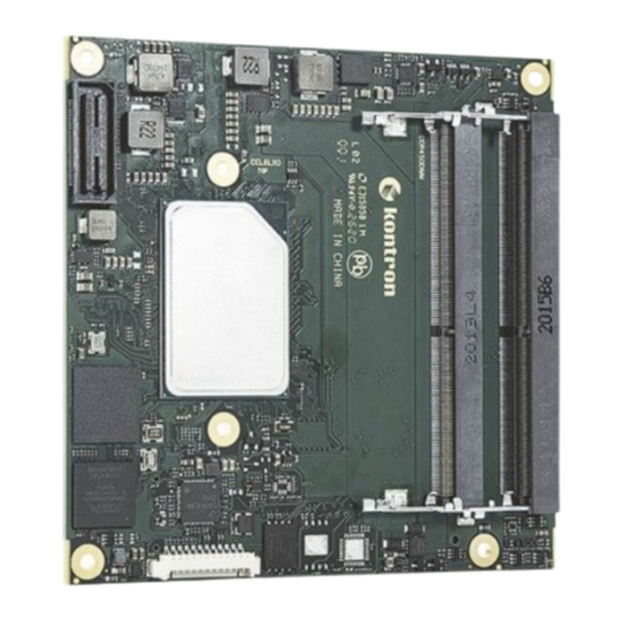
COMe-cEL6 - User Guide, Rev.1.2 List of Figures Figure 1: COMe-cEL6 Front Side ................................... 13 Figure 2: COMe-cEL6 Bottom Side ................................14 Figure 3: Block Diagram COMe-cEL6 ................................18 Figure 4: Module Temperature Sensors ..............................31 Figure 5: Fan Connector 3-Pin ..................................32 Figure 6: MTBF De-rating Values ................................ -
Page 13: 1/ Introduction
COMe-cEL6 - User Guide, Rev.1.2 1/ Introduction This user guide describes the COMe-cEL6 module made by Kontron and focuses on describing the modules special features. Kontron recommends users to study this user guide before powering on the module. 1.1. Product Description The COMe-cEL6 is small form factor COM Express®... -
Page 14: Product Naming Clarification
COMe Interface Connector X1B 1.2. Product Naming Clarification COM Express® defines a Computer-On-Module (COM), with all the components necessary for a bootable host computer, packaged as a super component. The product name for Kontron COM Express® Computer-On-Modules consists of: ... -
Page 15: Com Express® Documentation
COM Express® defines a Computer-On-Module (COM), with all the components necessary for a bootable host computer, packaged as a highly integrated computer. All Kontron COM Express® modules are very compact and feature a standardized form factor and a standardized connector layout that carry a specified set of signals. Each COM module is based on the COM Express®... -
Page 16: 2/ Product Specification
COMe-cEL6 - User Guide, Rev.1.2 2/ Product Specification 2.1. Module Variants The COMe-cEL6 is available in different processor, memory and temperature variants to cover demands in performance, price and power. The following tables list the module variants for the commercial and industrial temperature grades. - Page 17 COMe-cEL6 - User Guide, Rev.1.2 Part Number Cooling Description 36034-0000-99-0 HSP COMe-cEL6 (E2) THREAD Heatspreader for COMe-cEL6 commercial and E2, threaded mounting holes 36034-0000-99-1 HSP COMe-cEL6 (E2) THROUGH Heatspreader for COMe-cEL6 commercial and E2, through holes 36099-0000-99-0 COMe Active Uni Cooler COM Express®...
-
Page 18: Functional Specification
2.3.2. Processors The COMe-cEL6 is based on the Intel® series of Multi Chip Package (MCP) Atom™ X6000E series, Pentium® and Celeron® processors, with a Platform Controller Hub (PCH) on the same package (compact Type 3 BGA 35 mm x 24 mm package). -
Page 19: Table 5: Processor Specification
COMe-cEL6 - User Guide, Rev.1.2 The following table lists the specification of the COMe-cEL6 processor variants. Table 5: Processor Specification Intel® Celeron® Pentium® Celeron® Pentium® J6413 J6426 N6211 N6415 # of Cores # of Threads Cache 1.5 MByte 1.5 MByte 1.5 MByte... -
Page 20: Platform Controller Hub (Pch)
Kontron guarantees to maintain memory modules by replacing EOL memory modules with another qualified similar module. Kontron recommends using Kontron memory modules for prototype system(s) in order to prove the stability of the system and as a reference. -
Page 21: Graphics (Lvds Or Edp, Dp++)
Graphics (LVDS or eDP, DP++) The COMe-cEL6 supports up to three simultaneous displays on the Digital Display Interface (DDI), where DDIO (port A) is LVDS by default with the option to overlay to eDP requiring a hardware assembly, and DDI1 (port B) and DDI2 (Port c) support DP++. -
Page 22: Pci Express Lanes [0-5]
PCI Express Lanes [0-5] The COMe-cEL6 supports up to six high-speed PCI Express 3.0 lanes PCIe [0-5], allowing for the connection of up to six separate external PCIe devices. The default PCIe configuration is (6 x1) with options for (1 x2 + 4 x1), (2 x2 + 2x1) and (1 x4 + 2x1). -
Page 23: Sata
SATA Gen 3, 6 Gb/s to COMe 2.3.10. Ethernet LAN The COMe-cEL6 supports one Ethernet port with 1 Gb/s or on request up to 2.5 Gb/s. The main Ethernet PHY features are: Full and half duplex 10Base-T(e), 100Base-T, 1000Base-T and on request 2.5 GBase-T ... -
Page 24: Come High-Speed Serial Interfaces Overview
MDI differential line pairs If this type of integrated connector module (ICM) is chosen. 2.3.11. COMe High-speed Serial Interfaces Overview The COMe-cEL6 supports 12 HSIO lanes use for PCIe Gen 3.0, USB 3.1 Gen 2, SATA Gen 3 and GBE. The following table lists the high-speed lane combinations. HSIO... -
Page 25: Additional Features
Custom BIOS Settings/ Supported Flash Backup 2.3.14. Additional Features The following table lists General, Special and Optional COMe-cEL6 features. General Features On-module and external carrier boot from SPI LPC bus (default) pins shared with eSPI (eSPI overlay on request) LID Signal... -
Page 26: Electrical Specification
Power Supply Specification The COMe-cEL6 supports a supply voltage of 12 V (single power rail voltage) and a wide input voltage range of 8.5 V to 20 V. Other supported voltages are 5 V standby and 3.3 V RTC battery input. -
Page 27: Power Management
2.4.2. Power Management The COMe-cEL6 supports the Advanced Configuration and Power Interface (ACPI) version 6.0 to implement features such as power button, sleep button, and suspend and wake states. The Power management options are available within the BIOS set up menu: Advance>ACPI Settings>. -
Page 28: Power Supply Modes
2.4.3. Power Supply Modes The COMe-cEL6 supports single power supply mode and ATX power supply mode. To change the power supply mode set the ATX and single power supply controls as described in the following sections. 2.4.3.1. ATX Power Supply Mode To start the module in ATX mode, connect VCC and 5V Standby from a ATX PSU. -
Page 29: Table 9: Single Power Supply Mode Settings
COMe-cEL6 - User Guide, Rev.1.2 2.4.3.2. Single Power Supply Mode To start the module in single power supply mode, connect VCC power and open PWR_OK at the high level. VCC can be 8.5 V to 20 V. To power on the module from S5 state, press the power button or reconnect VCC. -
Page 30: Thermal Management
Both active and passive thermal management approaches can be used with the heatspreader plate. The optimum cooling solution depends on the COM Express® application and environmental conditions. Kontron’s active or passive cooling solutions are designed to cover the power and thermal dissipation for a commercial temperature range used in housing with a suitable airflow. -
Page 31: Temperature Sensors
COMe-cEL6 - User Guide, Rev.1.2 2.5.5. Temperature Sensors The thermal resistor (Figure 4, pos. 1) measures the Multi Chip Package (MCP) temperature. The thermal resistor is not capable of measuring very fast rises and falls in temperature and measurements may show a certain non- linearity. -
Page 32: On-Board Fan Connector
2.6. Environmental Specification The COMe-cEL6 supports two temperature grades commercial and Industrial (E2). The industrial temperature grade modules support an integrated heatspreader. For temperature grade information, see Chapter 2.1: Module Variants. Table 12: Temperature Grades and Humidity Specification... -
Page 33: Standards And Certifications
COMe-cEL6 - User Guide, Rev.1.2 2.7. Standards and Certifications The COMe-cEL6 complies with the following standards and certificates. If modified, the prerequisites for specific approvals may no longer apply. For more information, contact Kontron Support. Table 13: Standards and Certifications... -
Page 34: Figure 6: Mtbf De-Rating Values
Figure 6 shows MTBF de-rating values for commercial grade module variant when used in an office or telecommunications environment. Other environmental stresses (extreme altitude, vibration, salt-water exposure, etc.) lower MTBF values. Figure 6: MTBF De-rating Values COMe-cEL6 E2 x6425RE 16S 2.5G COMe-cEL6 J6426 & COMe- cEL6 E2 x6425RE www.kontron.com // 34... -
Page 35: Mechanical Specification
COMe-cEL6 - User Guide, Rev.1.2 2.8. Mechanical Specification The COMe-cEL6 is compliant with the COM Express® PICMG COM.0 Rev 3.0 mechanical specification. 2.8.1. Module Dimensions The compact module dimensions are: 95 mm x 95 mm (3.74” x 3.74“). Figure 7: Module Dimensions Top Side *All dimensions are in mm. -
Page 36: Module Height
COMe-cEL6 - User Guide, Rev.1.2 Figure 8: Module Dimensions Bottom Side *All dimensions are in mm. 2.8.2. Module Height The COM Express® specification defines a module height of approximately 13 mm, when measured from the bottom of the module’s PCB board, to the top of the heatspreader. -
Page 37: Metal Heat Slug Dimensions
COMe-cEL6 - User Guide, Rev.1.2 2.8.3. Metal Heat Slug Dimensions The metal heat slug (35 mm x 24 mm) is located on top of the multi-chip package. Figure 10: Metal Heat Slug Dimensions *All dimensions shown in mm. Metal heat slug www.kontron.com... -
Page 38: 3/ Features And Interfaces
WakeOnLAN (S3, S4) 3.2. eMMC Flash Memory (option) The on-module Embedded Multimedia Flash Card (eMMC) is eMMC 5.1 compatible. The standard COMe-cEL6 variants support MLC. On request eMMC pSLC can be offered. During the manufacturing process, Multi Level Cell (MLC) eMMC is reconfigured to act as pseudo Single Level Cell (pSLC) eMMC to provide improved reliability, endurance and performance. -
Page 39: Fast I2C
COMe-cEL6 - User Guide, Rev.1.2 3.4. Fast I2C The fast I2C bus transfers data between components data transfers at up to 400 kHz clock speed. The I2C controller supports: Multimaster transfers Clock stretching Collision detection Interruption on completion of an operation To change the I2C bus speed, in the BIOS setup menu select: Advanced>Miscellaneous>I2C Speed>... -
Page 40: Lpc
RTC voltage is generated by on-module regulators, to reduce RTC current draw. The COMe-cEL6 supports an internal RTC by default with the option for an external RTC on request. Using the COMe-cEL6 without RTC battery voltage supply may result in improper behavior. -
Page 41: Sdio (Option)
3.12.1. SPI Boot The SPI Flash chip stores the BIOS to be booted. The COMe-cEL6 supports SPI boot from the 32 MByte SPI Flash chip on the module and the external 32 MByte SPI Flash chip on the carrier board. The pins A34 (BIOS_DIS0#) and pin B88 (BIOS_DIS1#) select the SPI Flash boot source, see Table 16: SPI Boot Pin Configuration. -
Page 42: Booting The Spi Flash Chip
The COMe-cEL6 supports firmware TPM (fTPM) using the integrated TPM 2.0 capability of the Intel Platform Trusted Technology (Intel® PTT). Hardware TPM is an option. -
Page 43: Uart (Option)
With the aim to bring the system back from a non-responsive to normal state. The COMe-cEL6 supports a watchdog that works with two stages that can be programmed independently and used stage by stage. -
Page 44: 4/ System Resources
COMe-cEL6 - User Guide, Rev.1.2 4/ System Resources 4.1. I2C Bus The following table specifies the devices connected to the accessible I2C bus including the I2C address. The I2C bus is available at COMe pin A83, I2C_CK and pin A84, I2C_DAT. -
Page 45: 5/ Come Interface Connector
COMe-cEL6 - User Guide, Rev.1.2 5/ COMe Interface Connector The two 220-pin COMe interface connectors X1A and X1B, each with two rows called row A & B on primary connector X1A and row C & D on secondary connector X1B, are mounted on the bottom side of the module. -
Page 46: X1A And X1B Signals
PICMG specification COM.0 Rev 3.0 Type 10 standard. The information provided under type, module terminations and comments is complimentary to the COM.0 Rev 3.0 Type 6 standard. For more information, contact Kontron Support. Table 21: General Signal Description Type... -
Page 47: Come Interface Connectors (X1A, X1B) Pin Assignment
COMe-cEL6 - User Guide, Rev.1.2 5.3. COMe Interface Connectors (X1A, X1B) Pin Assignment The following tables list the pin assignment of the two 220-pin COMe interface connectors X1A (Row A1 to A110) and (Row B1 to B110) and X1B (Row C1 to C110) and (Row D1 to D110). - Page 48 COMe-cEL6 - User Guide, Rev.1.2 COMe Signal Description Type Termination Description USB_6_7_OC# USB overcurrent indicator port 6/7 I-3.3 PU 10 kΩ, 3.3 V (S5) USB4- USB 2.0 data differential pair port 4 DP-I/O Integrated PD 14.25 KΩ to USB4+ 24.8 kΩ in PCH...
- Page 49 COMe-cEL6 - User Guide, Rev.1.2 COMe Signal Description Type Termination Description LVDS_A3+ LVDS channel A DAT3 DP-O LVDS_A3- Power Ground PWR GND LVDS_A_CK+ LVDS channel A clock or EDP lane 3 transmit DP-O Clock 20 MHz to 80 MHz LVDS_A_CK-...
-
Page 50: Connector X1A Row B1 - B110
COMe-cEL6 - User Guide, Rev.1.2 5.3.2. Connector X1A Row B1 – B110 Table 23: Connector X1A Row B1 to B110 Pin Assignment COMe Signal Description Type Termination Description Power Ground PWR GND GBE0_ACT# Ethernet Controller activity LED indicator LPC_FRAME# / LPC Frame indicator / O-3.3 /... - Page 51 COMe-cEL6 - User Guide, Rev.1.2 COMe Signal Description Type Termination Description Power Ground PWR GND SPKR Speaker output provides the PC beep O-3.3 signal and is mainly intended for debugging purposes I2C_CK I2C port clock output O-3.3 PU 2.21 kΩ 3.3V...
- Page 52 COMe-cEL6 - User Guide, Rev.1.2 COMe Signal Description Type Termination Description LVDS_B2+ LVDS Channel B Dat2+/- DP-O LVDS_B2- LVDS_B3+ LVDS Channel B Dat3+/- DP-O LVDS_B3- LVDS/BKLT_EN LVDS /EDP panel backlight enable 0-3.3 PD 100 kΩ (ON) Power Ground PWR GND...
-
Page 53: Connector X1B Row C1 - C110
COMe-cEL6 - User Guide, Rev.1.2 5.3.3. Connector X1B Row C1 – C110 Table 24: Connectors X1B Row C1 to C110 COMe Signal Description Type Termination Comment Power ground PWR GND USB_SSRX0- USB SuperSpeed receive data pair 0 DP-I To USB hub... - Page 54 COMe-cEL6 - User Guide, Rev.1.2 COMe Signal Description Type Termination Comment DDI3_PAIR1+ Digital Display Interface pair 3 DDI3_PAIR1- DDI3_HPD RSVD Reserved for future use DDI3_PAIR2+ Digital Display Interface pair 2 DDI3_PAIR2- RSVD Reserved for future use DDI3_PAIR3+ Digital Display Interface pair 3...
- Page 55 COMe-cEL6 - User Guide, Rev.1.2 COMe Signal Description Type Termination Comment PEG_RX12+ PCI Express Graphics Receive Inputs differential Pair 12 PEG_RX12- Power ground PWR GND PEG_RX13+ PCI Express Graphics Receive Inputs differential Pair 13 PEG_RX13- Power ground PWR GND RSVD...
-
Page 56: Connector X1B Row D1 - D110
COMe-cEL6 - User Guide, Rev.1.2 5.3.4. Connector X1B Row D1 – D110 Table 25: Connector X1A Row D1 – D110 COMe Signal Description Type Termination Comment Power ground PWR GND USB_SSTX0- USB SuperSpeed transmit data path 0 DP-O USB_SSTX0+ Power ground... - Page 57 COMe-cEL6 - User Guide, Rev.1.2 COMe Signal Description Type Termination Comment DDI2_HPD DDI2 Hotplug Detect: Multiplexed with I-3.3 PD 100 KΩ DP2_HPD and HDMI2_HPD RSVD Reserved for future use DDI2_PAIR2+ Multiplexed with DP2_LANE2+/- and DP-O TMDS2_DATA0+/- DDI2_PAIR2- RSVD Reserved for future use...
- Page 58 COMe-cEL6 - User Guide, Rev.1.2 COMe Signal Description Type Termination Comment PEG_TX12+ PCI Express Graphics Transmit Output differential Pair 12 PEG_TX12- Power ground PWR GND PEG_TX13+ PCI Express Graphics Transmit Output differential Pair 13 PEG_TX13- Power ground PWR GND RSVD...
-
Page 59: 6/ Uefi Bios
6.2. Navigating the uEFI BIOS The COMe-cEL6 uEFI BIOS Setup program uses a hot key navigation system. The hot key legend bar is located at the bottom of the BIOS Setup screens. The following table provides a list of navigation hot keys available in the legend bar. -
Page 60: Getting Help
COMe-cEL6 - User Guide, Rev.1.2 The currently active menu and the currently active uEFI BIOS Setup item are highlighted in white. Use the left and right arrow keys to select the Setup menu. Each Setup menu provides two main frames. The left frame displays all available functions and configurable functions are displayed in blue. -
Page 61: Main Setup Menu
COMe-cEL6 - User Guide, Rev.1.2 6.4.1. Main Setup Menu The Main setup menu lists sub-screens and second level sub-screens of the functions supported within the Main setup menu. Figure 13: Main Setup Menu Screen The following table shows the Main Menu sub-screens and describes the function. Default settings are in bold. -
Page 62: Advanced Setup Menu
COMe-cEL6 - User Guide, Rev.1.2 6.4.2. Advanced Setup Menu The Advanced Setup menu lists sub-screens and second level sub-screens of the functions supported within the Advanced setup menu. Setting items, on this screen, to incorrect values may cause system malfunctions. - Page 63 COMe-cEL6 - User Guide, Rev.1.2 Sub-screen Next Level Sub-screens / Description RC ACPI Wake System System wake on alarm event. When enabled system will wake on the Settings> from S5 via RTC> hr:min::sec::specified (continued) [Enabled, Disabled] Low Power S0 Determines If ACPI Lower power S0 idle capability (mutually exclusive Idle Capability>...
- Page 64 COMe-cEL6 - User Guide, Rev.1.2 Sub-screen Next Level Sub-screens / Description Power and CPU Power Read only field Perfomance> Management> P1 to P3 Fused Max Core Ratio Boot Select the performance state that the BIOS will set Performance starting from rest vector.
- Page 65 COMe-cEL6 - User Guide, Rev.1.2 Sub-screen Next Level Sub-screens / Description CPU Power View/Configure Power and 2-Core Ratio Range 0 to 83. Minimum range Perfomance> Management> Turbo Options> Limit Override> varies between processors. This (continued) (continued) (continued) 2-Core ration limit must be less than or equal to 1-Core ratio limit.
- Page 66 COMe-cEL6 - User Guide, Rev.1.2 Sub-screen Next Level Sub-screens / Description CPU Power Power and IO MWait Enable: mapa IO read instructions sent to IO Perfomance> Management> Redirection> registers PMG_IO_BASE_ADDRBASE+off set to (continued) (continued) MWait (offset) [Enabled, Disabled] Package Maximum c-state limit setting.
- Page 67 COMe-cEL6 - User Guide, Rev.1.2 Sub-screen Next Level Sub-screens / Description Power and CPU Power Custom P- Sets the number of customer P-states. At least 2 Performance> Management> State Table> states must be present. [0] (continued) (continued) Power Limit 3 Read only field Settings>...
- Page 68 COMe-cEL6 - User Guide, Rev.1.2 Sub-screen Next Level Sub-screens / Description PCH-FW Firmware Update Anti-Rollback Set HW- Hardware enforced anti-rollback Configuration> Configuration> enforced for current ARB-SVN value. Configuration> (continued) (continued) Anti-Rollback Firmware with lower ARB-SVN is (continued) for Current blocked from execution. Value SVN>...
- Page 69 COMe-cEL6 - User Guide, Rev.1.2 Sub-screen Next Level Sub-screens / Description Thermal Platform Critical Trip Controls temperature of ACPI Critical Trip Point, at Consideration> Thermal Point> which OS shuts down the system. Note: 119 C is the (continued) Configuration> PLAN of Record (POR) for all Intel mobile processors.
- Page 70 COMe-cEL6 - User Guide, Rev.1.2 Sub-screen Next Level Sub-screens / Description ACPI D3Cold USB Port 2> USB RTD3 support for super speed USB 3.1 and high speed USB 2.0 Settings> devices [Enabled, Disabled] (continued) ZPODD> Zero power ODD (ZPODD) only for boar with SPODD support [Enabled, Disabled] WWAN>...
- Page 71 COMe-cEL6 - User Guide, Rev.1.2 Sub-screen Next Level Sub-screens / Description Trusted Pending Schedule an operating for security device. Note: computer reboots Computing> Operation> during restart to change the state of security device. (continued) [None, Clear] Platform [Enabled, Disabled] Hierarchy>...
- Page 72 COMe-cEL6 - User Guide, Rev.1.2 Sub-screen Next Level Sub-screens / Description Miscellaneous> Lid Switch Mode> Shows or hides LID switch in ACPI OS. (continued) [Enabled, Disabled] Sleep Button Shows or hides sleep button in ACPI OS Mode> [Enabled, Disabled] ACPI Temperature Sets mode for temperature polling through OSPM Polling>...
- Page 73 COMe-cEL6 - User Guide, Rev.1.2 Sub-screen Next Level Sub-screens / Description Hardware External Fan> Monitor> Fan Control> Sets fan control mode where disable totally stops the fan.[Disabled, (continued) Manual, Auto] Fan Pulse> No. Pulses the fan produces during one revolution (range 1 to 4)
- Page 74 COMe-cEL6 - User Guide, Rev.1.2 Sub-screen Next Level Sub-screens / Description Active Serial Logical Device Read only field Configuration> port> Settings IO=2F8h; IRQ=3; (continued) (continued) Current> Possible: Use Allows the user to change the device’s resource Automatic settings. New settings are reflected on the setup Settings>...
- Page 75 COMe-cEL6 - User Guide, Rev.1.2 Sub-screen Next Level Sub-screens / Description XHCI Hand-off> This is a work around for OSs without XHCI hand-off support. The Configuration> XHCI ownership change should be claimed by XHCI driver (continued) [Enabled, Disabled] USB Mass Storage [Enabled, Disabled] Driver Support>...
- Page 76 COMe-cEL6 - User Guide, Rev.1.2 Sub-screen Next Level Sub-screens / Description User Password Admin Password Read only field Management> Management> [Not Installed] Change Admin New password must be between 8 and 32 Characters include lower Password> and upper case, number and symbol.
-
Page 77: Chipset Setup Menu
COMe-cEL6 - User Guide, Rev.1.2 6.4.3. Chipset Setup Menu The Chipset Setup menu lists sub-screens and second level sub-screens of the functions supported within the Chipset setup menu. Figure 15: Chipset Setup Menu The following table shows sub-screens and describes the function. Default settings are in bold. - Page 78 COMe-cEL6 - User Guide, Rev.1.2 Sub-screen Next Level Sub-screens / Description System Agent Memory Memory Memory Power Refresh_ [Disables, 1- Enabled for Configuration> Thermal and Thermal (SA) Warm or Hot, 2- Configuration> Throttling> (continued) Mode> Configuration> Enabled Hot only] (continued)
- Page 79 COMe-cEL6 - User Guide, Rev.1.2 Sub-screen Next Level Sub-screens / Description System Agent Memory Train On Warm [Enabled, Disabled] Configuration> (SA) Boot> Configuration> (continued) BDAT Memory Read Only field (continued) Test Type> [Rank margin Tool Rank] Graphics Skip Scanning of Enabled- will not scan for external Gfx card on PEG and Configuration>...
- Page 80 COMe-cEL6 - User Guide, Rev.1.2 Sub-screen Next Level Sub-screens / Description System Agent CPU Crash Log [Enabled, Disabled] (SA) (Device 10)> Configuration> CRID Support> SA CRID and TCSS CRID control for Intel SIPP (continued) [Enabled, Disabled] Above 4 GB Enables automatically when aperture size is set to 2048 MB.
- Page 81 COMe-cEL6 - User Guide, Rev.1.2 Sub-screen Next Level Sub-screens / Description PCH-IO PCI Express PCIE Express PTM> Precision Time Measurement Configuration> Root Port Configuration> Enabled, Disabled] [1 to 4]> (continued) (continued) DPC> Downstream Port Containment (continued) [Enabled, Disabled] EDPC> Extensions for Downstream Port...
- Page 82 COMe-cEL6 - User Guide, Rev.1.2 Sub-screen Next Level Sub-screens / Description PCH-IO PCI Express PCIE Express PCH PCIe LTR Configuration Configuration> Root Port Configuration> LTR> PCIe latency reporting [1 to 4]> (continued) (continued) [Enabled, Disabled] (continued) Snoop Latency Disabled- disable override Override>...
- Page 83 COMe-cEL6 - User Guide, Rev.1.2 Sub-screen Next Level Sub-screens / Description SATA Controllers> PCH-IO SATA [Enabled, Disabled] Configuration> Configuration> SATA Port Multiplier> Determines how the SATA controllers(s) operate (continued) [AHCI] SATA Mode Selection> [Enabled, Disabled] SATA Test Mode> [Enabled, Disabled] Software Feature HDD Unlock>...
- Page 84 COMe-cEL6 - User Guide, Rev.1.2 Sub-screen Next Level Sub-screens / Description PCH-IO SATA SATA Port 0 Disable is default- check module design before Configuration> Configuration> RXPolarity> enabling. (continued) (continued) [Enabled, Disabled] DITO Configuration> [Enabled, Disabled] DITO Value> Read Only port [625] DM value>...
- Page 85 COMe-cEL6 - User Guide, Rev.1.2 Sub-screen Next Level Sub-screens / Description PCH-IO HD Audio HD Audio> Enabled: HDA unconditionally enabled Configuration> Configuration> (continued) [Enabled, Disabled] (continued) (continued) Audio DSP> Enables or disables the Audio DSP. [Enabled, Disabled] HD Audio Advanced...
- Page 86 COMe-cEL6 - User Guide, Rev.1.2 Sub-screen Next Level Sub-screens / Description PCH/IO Serial IO UART2 Controller Set UART2 mode Configuration> Configuration> (COMe UART1> -DBG used for BIOS log print and/or Kernel OS (continued) (continued) UART2 Controller debug (COMe UART1> -COM-16550 Compatibility serial power with power...
- Page 87 COMe-cEL6 - User Guide, Rev.1.2 Sub-screen Next Level Sub-screens / Description PCH/IO TSN GBE PSE TSN GBE 0 Link PSE TSN GBE 0 link speed configuration. Configuration> Configuration> Speed> [RefClk 38.4MHz 2.5Gbps, RefClk 38.4MHz 1Gbps] (continued) (continued) Flex IO Lane Read only field Assignment>...
- Page 88 COMe-cEL6 - User Guide, Rev.1.2 Sub-screen Next Level Sub-screens / Description PCH/IO Extended BIOS Enable: redirects memory cycles falling in a specific area to SPI flash Configuration> Range Decode> controller. (continued) [Enabled, Disabled] Sub-Screen Next level Sub-screens / Description Data Format>...
-
Page 89: Security Setup Menu
COMe-cEL6 - User Guide, Rev.1.2 6.4.4. Security Setup Menu The security Setup menu lists sub-screens and second level sub-screens of the functions supported within the Security setup menu. Figure 16: Security Setup Menu The following table shows the Security sub-screens and functions and describes the content. - Page 90 COMe-cEL6 - User Guide, Rev.1.2 Sub-screen Next Level Sub-screens / Description PO: CT120BX500SSD1> Set User Set HDD user password. (continued) Password> Advisable to power cycle system after setting Hard Disk Passwords. Discard or save changes option in setup does not have any impact on HDD when password is set or removed.
-
Page 91: Boot Setup Menu
COMe-cEL6 - User Guide, Rev.1.2 6.4.5. Boot Setup Menu The Boot Setup menu lists sub-screens of the functions supported within the Boot setup menu. Figure 17: Boot Setup Menu Screen The following table shows the Boot Setup sub-screens and functions and describes the content. Default settings are in bold. -
Page 92: Save And Exit Setup Menu
COMe-cEL6 - User Guide, Rev.1.2 6.4.6. Save and Exit Setup Menu The Save and Exit Setup menu lists sub-screens of the functions supported within the Save and Exit setup menu. Figure 18: Save and Exit Setup Menu Screen The following table shows the Save and Exit sub-screens and functions and describes the content. -
Page 93: The Uefi Shell
6.5. The uEFI Shell The Kontron uEFI BIOS features a built-in and enhanced version of the uEFI Shell. For a detailed description of the available standard shell scripting, refer to the EFI Shell User Guide. For a detailed description of the available standard shell commands, refer to the EFI Shell Command Manual. -
Page 94: Uefi Shell Scripting
Initially searches for Kontron flash-stored startup script. If there is no Kontron flash-stored startup script present, then the uEFI-specified startup.nsh script is used. This script must be located on the root of any of the attached FAT formatted disk drive. -
Page 95: Firmware Update
6.7. Firmware Update Firmware updates are typically delivered as a ZIP archive. Please find the latest available BIOS-ZIP archive on Kontron's Customer Section. Further information about the firmware update procedure can be found in the included "flash_instruction.txt"-file. Register for Kontron’s Customer Section to get access to BIOS downloads and PCN service. -
Page 96: 7/ Technical Support
The buyer accepts responsibility for all freight charges for the return of goods to Kontron's designated facility. Kontron will pay the return freight charges back to the buyer's location in the event that the equipment is repaired or replaced within the stipulated warranty period. Follow these steps before returning any product to Kontron. -
Page 97: 8/ Warranty
8.1. Limitation/Exemption from Warranty Obligation In general, Kontron shall not be required to honor the warranty, even during the warranty period, and shall be exempted from the statutory accident liability obligations in the event of damage caused to the product due to failure to observe the following: ... -
Page 98: List Of Acronyms
COMe-cEL6 - User Guide, Rev.1.2 List of Acronyms Table 33: List of Acronyms ACPI Advanced Configuration and Power Keyboard Video Mouse Interface Low Pin Count (Bus) Application Programming Interface LVDS Low Voltage Differential Signaling Base Management Controller Media Access Control (Ethernet layer) -
Page 99: About Kontron
COMe-cEL6 – User Guide, Rev.1.2 About Kontron Kontron is a global leader in IoT/Embedded Computing Technology (ECT). As a part of technology group S&T, Kontron, together with its sister company S&T Technologies, offers a combined portfolio of secure hardware, middleware and services for Internet of Things (IoT) and Industry 4.0 applications. With its standard products and tailor-made solutions based on highly reliable state-of-the-art embedded technologies, Kontron provides secure and innovative applications for a variety of industries.
Need help?
Do you have a question about the COMe-cEL6 and is the answer not in the manual?
Questions and answers