Table of Contents
Advertisement
Quick Links
Advertisement
Table of Contents

Related Manuals for Kontron COMh-sdID


Summary of Contents for Kontron COMh-sdID
- Page 1 User Guide Rev. 1.0...
-
Page 2: Table Of Contents
COMh-sdID User Guide Table of Contents 1. General Information ........................1.1 Disclaimer ..........................1.2 Intended Use ........................... 1.3 Terms and Conditions ......................1.4 Customer Support ........................1.5 Customer Service ........................1.6 Customer Comments ......................1.7 Symbols ............................ 1.8 For Your Safety ........................ - Page 3 3.7 Thermal Management ......................3.7.1 Heatspreader Plate Assembly .................... 3.7.2 Active/Passive Cooling Solutions ..................3.7.3 Operating with Kontron Heatspreader Plate (HSP) Assembly ..........3.7.4 Operating without Kontron Heatspreader Plate (HSP) Assembly ........3.7.5 Temperature Sensors ......................3.7.6 On-Module Fan Connector ....................
- Page 4 COMh-sdID User Guide 6. Technical Support ........................6.1 Warranty ..........................6.2 Returning Defective Material ..................... 7. Document Revision ........................www.kontron.com...
-
Page 5: General Information
1. General Information 1.1 Disclaimer Kontron would like to point out that the information contained in this user guide may be subject to alteration, particularly as a result of the constant upgrading of Kontron products. This document does not entail any guarantee on the part of Kontron with respect to technical processes described in the user guide or any product characteristics set out in the user guide. -
Page 6: Intended Use
PHYSICAL OR ENVIRONMENTAL DAMAGE (COLLECTIVELY, “HIGH RISK APPLICATIONS”). You understand and agree that your use of Kontron devices as a component in High Risk Applications is entirely at your risk. To minimize the risks associated with your products and applications, you should provide adequate design and operating safeguards. -
Page 7: Terms And Conditions
Kontron sells products worldwide and declares regional General Terms & Conditions of Sale, and Purchase Order Terms & Conditions. Visit https://www.kontron.com/terms-and-conditions. For contact information, refer to the corporate offices contact information on the last page of this user... -
Page 8: Symbols
COMh-sdID User Guide 1.7 Symbols The following symbols may be used in this user guide of COMh-sdID simple Box Info-Box Important-Box Alert-Box Tip-Box Help-Box Todo-Box Download-Box www.kontron.com 4/58... -
Page 9: For Your Safety
COMh-sdID User Guide 1.8 For Your Safety Your new Kontron product was developed and tested carefully to provide all features necessary to ensure its compliance with electrical safety requirements. It was also designed for a long fault-free life. However, the life expectancy of your product can be drastically reduced by improper treatment during unpacking and installation. -
Page 10: Lithium Battery Precautions
Dispose of used batteries according to the manufacturer’s instructions. 1.12 General Instructions on Usage In order to maintain Kontron’s product warranty, this product must not be altered or modified in any way. Changes or modifications to the product, that are not explicitly approved by Kontron and described in this user guide or received from Kontron Support as a special handling instruction, will void your warranty. -
Page 11: Quality And Environmental Management
COMh-sdID User Guide 1.13 Quality and Environmental Management Kontron aims to deliver reliable high-end products designed and built for quality, and aims to complying with environmental laws, regulations, and other environmentally oriented requirements. For more information regarding Kontron’s quality and environmental responsibilities, visit https://www.kontron.com/en/quality-management. -
Page 12: Introduction
Table 1: COM-HPC® Product Naming Clarification 2.2 Product description The COMh-sdID with scalability from 4 to 20 cores and SKUs for an extended temperature range and 24×7 / 10 years reliability allows very robust implementations for harsh environments and extreme conditions in a small mechanical footprint. -
Page 13: Com-Hpc® Documentation
2.4 COM-HPC® Server Functionality All Kontron COM-HPC® Server modules are popolated two 400-pin connectors, each has 4 rows called A to D on connector J1 and row E to H on connector J2. The COM-HPC® Server Computer-on-Module features the following maximum amount of interfaces according to the PICMG module pinout type. - Page 14 COMh-sdID User Guide has many advantages of a customized computer-board design and, additionally, delivers better obsolescence protection, heavily reduced engineering effort, and faster time to market. www.kontron.com 10/58...
-
Page 15: Product Specification
Kontron Sales Representative or Kontron Inside Sales. 3.2.1 Cooling Any LGA115x cooler can be used for the COMh-sdID. In this case please use our HSD01-0000-99-A COMh-sdID (E2) Adapter and HSD01-0000-99-B COMh-sdID (E2) Backplate for cooler mounting. -
Page 16: Dimm Memory
97101-1632-SDID DDR4-3200 RDIMM 16GB ECC E2_SDID 16GB ECC -40°C to +85°C 97101-3232-SDID DDR4-3200 RDIMM 32GB ECC E2_SDID 32GB ECC -40°C to +85°C 97101-6432-SDID DDR4-3200 RDIMM 64GB ECC E2_SDID 64GB ECC -40°C to +85°C Table 6: RDIMM memory modules for COMh-sdID available from Kontron 3.2.3 Evaluation Carrier Kontron PN... -
Page 17: Block Diagram
COMh-sdID User Guide 3.3.2 Block Diagram Figure 1: COMh-sdID Blockdiagram www.kontron.com 13/58... -
Page 18: Top Side
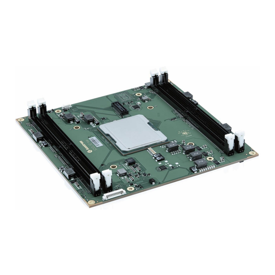
COMh-sdID User Guide 3.3.3 Top Side Figure 2: COMh-sdID Front Side Processor 4x DDR4 DIMM sockets Fan Connector Optional NVMe Programming connector for embedded controller XDP debug port (not populated on production units) www.kontron.com 14/58... -
Page 19: Bottom Side
4 mounting holes - for heatspreader to module, module to carrier mounting 3.3.5 Processor (CPU) The COMh-sdID is based on the Intel® Xeon® D-2700 processor family, the next generation System- on-Chip (SoC) with processor cores built using Intel 10-nanometer process technology. The three major complexes in this highly-integrated SoC are referred to as CPU, PCH and NAC. - Page 20 COMh-sdID User Guide industrial environments. Topline Specifications are: Up to 20 processor cores based on architecture code name Ice Lake server: Each core has L1 (first-level) data and instruction caches: 48 KB data, 64-byte cache line size parity protected 32 KB instruction, 64-byte cache line size parity protected Mid-Level Cache (MLC) unified instruction/data cache, ECC protected:...
-
Page 21: System Memory
For more details please see Intel document #631107 and/or contact Kontron Support 3.3.6 System Memory The COMh-sdID offers 4x DIMM sockets supporting up to 64 GByte of RDIMM ECC memory per socket. Socket 288-pin Memory Type Registered ECC DIMM 1.2V... - Page 22 COMh-sdID User Guide HSIO Lane# PCIe Gen 3.0 USB 3.0 SATA Description PCIe For onboard GbE controller routed to COM-HPC Connector - NBASE-T SATA 0 COM-HPC Connector - SATA #0 PCIe Option: For onboard NVMe SATA 1 COM-HPC Connector - SATA #1...
-
Page 23: Interfaces
COMh-sdID User Guide 3.4 Interfaces 3.4.1 PCIe COM-HPC allows for up to 49 PCIe lanes on the Client Module pin-out, and for up to 65 PCIe lanes on the Server Module. The PCIe lanes are divided into 5 Groups: Group 0 Low: PCIe lanes 0:7 and also an additional lane for BMC use... - Page 24 COMh-sdID User Guide COMh Group COMh Lane CPU PCIe Lane Lane Config PCIe Gen CPU PCIE 0 CPU PCIE 1 CPU PCIE 2 CPU PCIE 3 CPU PCIE 4 CPU PCIE 5 CPU PCIE 6 CPU PCIE 7 CPU PCIE 8...
-
Page 25: Usb
To realize a COM-HPC USB 3.2 Gen 1, Gen 2, Gen 2×2 or USB4 port, one of the four available USB 2.0 ports from the USB[0:3] pool must be used along with the SuperSpeed pins. The COMh-sdID supports 4x USB 3.0 ports. COM-HPC connector HSIO Lane# USB Speed Comment USB0 USB 3.0... - Page 26 COMh-sdID User Guide The COMh-sdID supports one 1/2.5GBASE-T port and and up to eight KR interfaces. HSIO lane #16 of the integrated SOC PCH is used as PCIe Gen 3.0 lane for the onboard 1/2.5 GbE Controller Intel i226 (see chapter 3.3.7 High-Speed Interface Overview).
- Page 27 Table 16: Mapping of COM-HPC Server specification to CEI interface In general the COMh-sdID can support the LAN configurations - enabled by different LEK (LAN Enabling Kit) files - which are aligned with the CEI interface. These are overall described in the following table.
-
Page 28: Graphics Interfaces
COMh-sdID User Guide Figure 6: Supported LAN configs The COMh-sdID is preconfigured with CFG 7.0 supporting 4 ports. For other configurations please contact Kontron Support Please get familiar with Intel documents #631178 and #645149 3.4.5 Graphics Interfaces A COM-HPC Server module doesn't support graphic interfaces. -
Page 29: Uart
Mini-PCIe or M.2 cards. Care has to be taken that the logic I/O levels match up. The UART interfaces on the COMh-sdID is supported by default via the EC (embedded controller). It can be reconnected to the SOC's PCH's UARTs on request. -
Page 30: Espi
Do not use Carrier Module Table 19: BIOS Boot options on the COMh-sdID 3.4.10 eSPI COM-HPC supports an eSPI port for general purpose I/O. The eSPI interface (like LPC before it) can be useful for general purpose devices such as Carrier Super I/O devices, Carrier CPLDs or FPGAs, hardware monitoring devices, and others. -
Page 31: I2C
Table 21: I2C interfaces on COMh-sdID 3.4.12 GPIO The COMh-sdID offers 12 GPIO pins on the dedicated pins of COM-HPC®. The type of termination resistor used sets the direction of the GPIO; where GPI terminations are pull-up resistors, and GPO terminations are pull-down resistors. -
Page 32: Features
- supporting watchdog functions The EC is accessible through the API in the Board Support Package. 3.5.3 Trusted Platform Module (TPM) The COMh-sdID supports a TPM chip which is directly connected to a dedicated SPI interface from the SOC-PCH. www.kontron.com... -
Page 33: Watchdog
The COMh-sdID supports typical RTC values of 3 V and less than 10 μA. When powered by the main power supply on-module regulators generate the RTC voltage, to reduce RTC current draw. The RTC’s battery voltage range is 2.8 V to 3.47 V. -
Page 34: Features On Request
The NVMe is based on TLC technology and can be configured as pSLC as well. Configuring the TLC- NVMe as pSLC results in dividing the capacity by three. 3.5.7 Features on Request On the COMh-sdID following optional features are available on request: Optional Features (on request) Up to 1 TByte NVMe PCIe SSD NAND Flash NVMe SSD - TLC technology - configuration as pSLC can be offered... -
Page 35: Electrical Specification
COMh-sdID User Guide 3.6 Electrical Specification The module powers on by connecting to a carrier board via the COM-HPC interface connectors. The COM-HPC interface connector pins on the module limit the amount of power received. Before connecting the module’s interface connector to the carrier board’s corresponding connector, ensure that the carrier board is switched off... -
Page 36: Power Management
COMh-sdID User Guide incorrectly or even suffer a reduction of MTBF. The minimum OFF time depends on the implemented PSU model and other electrical factors and must be measured individually for each case. Power Supply Voltage Rise Time The input voltage rise time is 0.1 ms to 20 ms from input voltage ≤10% to nominal input voltage. To comply with the ATX specification there must be a smooth and continuous ramp of each DC input... - Page 37 COMh-sdID User Guide Power Supply Control Signals Power supply control settings are set in the BIOS and enable the module to shut down, reset and wake from standby. COM-HPC Signal Pin Description A PWRBTN# falling edge signal creates power button event (50 ms ≤ t < 4 s, typical 400 ms) at low level).
-
Page 38: Thermal Management
3.7 Thermal Management 3.7.1 Heatspreader Plate Assembly A heatspreader plate assembly is available from Kontron for the COMh-sdID. The heatspreader plate assembly is NOT a heat sink. The heatspreader plate transfers heat as quickly as possible from the processor using a copper core positioned directly above the processor and a Thermal Interface Material (TIM). -
Page 39: Temperature Sensors
Figure 7: Module Temperature Sensor 3.7.6 On-Module Fan Connector The module's fan connector powers, controls and monitors an external fan. To connect a standard 3- pin connector fan to the module, use Kontron's fan cables: KAB-HSP 200 mm (96079-0000-00-0) KAB-HSP 400 mm (96079-0000-00-2) www.kontron.com... - Page 40 COMh-sdID User Guide Position of the fan connector see chapter 3.3.3 Pin Signal Description Type Fan_Tach_IN# Fan input voltage from COMe connector Input V_FAN 12 V ±10% (max.) across module input range PWR Power GND Table 27: Fan Connector (3-Pin) Pin Assignment Always check the fan specification according to the limitations of the supply current and...
-
Page 41: Mechanical Specification
COMh-sdID User Guide 3.8 Mechanical Specification The COMh-sdID is compatible with the COM-HPC® Server Size D mechanical specification. 3.8.1 Module Dimensions Figure 8: Module Dimensions 3.8.2 Module Height The COM-HPC/Server specification defines a module height of approximately 18mm, when measured from the bottom of the module's PCB board to the top of the heatspreader. -
Page 42: Heatspreader Plate Assembly Dimension
COMh-sdID User Guide Figure 9: Module and Carrier Height with 10mm and 5mm connector height 3.8.3 Heatspreader Plate Assembly Dimension Please check our Customer Section for Heatspreader 3D models and drawings. www.kontron.com 38/58... -
Page 43: Environmental Specification
COMh-sdID User Guide 3.9 Environmental Specification The COMh-sdID supports commercial and industrial temperature grades. Environmental Description Operating 0°C to +60°C (32°F to 140°F) Commercial Grade Non-operating -30°C to +85°C (-22°F to 185°F) Operating -40°C to +85°C (-40°F to 167°F) Industrial Grade (E2) Non-operating -30°C to +85°C (-22°F to 185°F) -
Page 44: Compliance
COMh-sdID User Guide 3.10 Compliance The COMh-sdID complies with the following or the latest status thereof. If modified, the prerequisites for specific approvals may no longer apply. For more information, contact Kontron Support. Europe - CE Mark 2014/30/EU: Electromagnetic Compatibility... -
Page 45: Mtbf
COMh-sdID User Guide 3.11 MTBF The MTBF (Mean Time Before Failure) values were calculated using a combination of the manufacturer’s test data (if available) and the Telcordia (Bellcore) issue 2 calculation for the remaining parts. The Telcordia calculation used is “Method 1 Case 3” in a ground benign, controlled environment. This particular method takes into account varying temperature and stress data and the system is assumed to have not been burned-in. -
Page 46: Com-Hpc Interface Connector
COMh-sdID User Guide 4. COM-HPC Interface Connector The COMh-sdID is a COM-HPC® Server module populated with two 400-pin connectors J1 and J2; each with 4 rows called rows and all rows are named A to D on the primary connector J1... -
Page 47: J1 And J2 Signals
COMh-sdID User Guide from the main power supply. Failure to disconnect the main power supply could result in personal injury and damage to the module and/or carrier board. Observe that only trained personnel aware of the associated dangers connect the module, within an access controlled ESD-safe workplace. -
Page 48: Connector J1
COMh-sdID User Guide 4.3 Connector J1 4.3.1 Pins A1 - A100 / B1 - B100 Row A Row B Pin # Name Type / Module Termination Name Type / Module Termination Main Supply Input Main Supply Input Main Supply Input PWRBTN# In - 10K PU (3.3V S5) -
Page 49: Pins C1 - C100 / D1 - D100
COMh-sdID User Guide Row A Row B Pin # Name Type / Module Termination Name Type / Module Termination eSPI_CLK Out – 20K PD eSPI_CS0# Out – 20K PU (1.8V S5) Ground eSPI_CS1# Out – 20K PU (1.8V S5) PCIe_CLKREQ0_LO# In - 10K PU (3.3V S0) - Page 50 COMh-sdID User Guide Row C Row D Pin # Name Type / Module Termination Name Type / Module Termination VIN_PWROK In - 22K PU (3.3V S0/S5) Main Supply Input Main Supply Input Main Supply Input SUS_S4_S5# Out - Push-pull Main Supply Input...
-
Page 51: Connector J2
COMh-sdID User Guide Row C Row D Pin # Name Type / Module Termination Name Type / Module Termination PCIe01_RX+ HSIO Receive Ground Ground PCIe02_TX- HSIO Transmit / 100nF series PCIe02_RX- HSIO Receive PCIe02_TX+ HSIO Transmit / 100nF series PCIe02_RX+... - Page 52 COMh-sdID User Guide Row E Row F Pin # Name Type / Module Termination Name Type / Module Termination RSVD Not connected ETH4-7_PHY_RST# Out – 10k PD Ground ETH4-7_PRSNT# In – 2K2 PU (3.3V S5) RSVD Not connected RSVD Not connected...
-
Page 53: Pins G1 - G100 / H1 - H100
COMh-sdID User Guide Row E Row F Pin # Name Type / Module Termination Name Type / Module Termination PCIe49_TX+ HSIO Transmit / 100nF series Ground Ground PCIe50_RX- HSIO Receive PCIe50_TX- HSIO Transmit / 100nF series PCIe50_RX+ HSIO Receive PCIe50_TX+... - Page 54 COMh-sdID User Guide Row G Row H Pin # Name Type / Module Termination Name Type / Module Termination PCIe41_RX+ HSIO Receive Ground Ground PCIe42_TX- HSIO Transmit / 100nF series PCIe42_RX- HSIO Receive PCIe42_TX+ HSIO Transmit / 100nF series PCIe42_RX+...
- Page 55 COMh-sdID User Guide Row G Row H Pin # Name Type / Module Termination Name Type / Module Termination PCIe61_RX+ HSIO Receive Ground Ground PCIe62_TX- HSIO Transmit / 100nF series PCIe62_RX- HSIO Receive PCIe62_TX+ HSIO Transmit / 100nF series PCIe62_RX+...
-
Page 56: Uefi Bios
COMh-sdID User Guide 5. UEFI BIOS 5.1 Starting the UEFI BIOS The COMh-sdID uses a Kontron-customized, pre-installed and configured version of AMI Aptio® V BIOS based on the Unified Extensible Firmware Interface (UEFI) specification and the Intel® Platform Innovation Framework for EFI. -
Page 57: Navigating The Uefi Bios
COMh-sdID User Guide 5.2 Navigating the UEFI BIOS The COMh-sdID UEFI BIOS Setup program uses a hot key navigation system with a corresponding legend bar displayed on the setup screens. The following table provides a list of navigation hot keys available in the legend bar. -
Page 58: Uefi Shell
COMh-sdID User Guide 5.5 UEFI Shell The Kontron UEFI BIOS features a built-in and enhanced version of the UEFI Shell. For a detailed description of the available standard shell scripting, refer to the EFI Shell User Guide. For a detailed description of the available standard shell commands, refer to the EFI Shell Command Manual. -
Page 59: Uefi Shell Scripting
Initially searches for Kontron flash-stored startup script If there is no Kontron flash-stored startup script present, then the UEFI-specified startup.nsh script is used. This script must be located on the root of any of the attached FAT-formatted disk... - Page 60 RMA number. The buyer accepts responsibility for all freight charges for the return of goods to Kontron’s designated facility. Kontron will pay the return freight charges back to the buyer’s location in the event that the equipment is repaired or replaced within the stipulated warranty period.
- Page 61 fill out the above information in the RMA Request form for each product. Send the completed RMA-Request form to the fax or email address given below at Kontron Europe GmbH. Kontron will provide an RMA-Number.
- Page 62 COMh-sdID User Guide 7. Document Revision The following table shows the revision of this document. Revision Author Date Comment 2023-02-15 initial preliminary release 2023-05-16 updated several pages 2023-07-03 released version Table 40: Document Revision Table www.kontron.com 58/58...
Need help?
Do you have a question about the COMh-sdID and is the answer not in the manual?
Questions and answers