Table of Contents
Advertisement
Quick Links
Advertisement
Table of Contents

Related Manuals for Kontron COMe-mTT10


Summary of Contents for Kontron COMe-mTT10
- Page 1 COMe-mTT10 Document Revision 120 www.kontron.com...
-
Page 3: Table Of Contents
MTBF............................22 Mechanical Specification......................23 3.9.1 Module Dimension........................23 3.9.2 Height on Top..........................23 3.9.3 Height on Bottom........................23 3.9.4 Mechanical Drawing........................23 3.10 Thermal Management........................24 3.11 Heatspreader..........................24 Features and Interfaces...............25 Onboard SSD..........................25 S5 Eco Mode..........................26 www.kontron.com... - Page 4 COMe-mTT10 / LPC............................27 Serial Peripheral Interface (SPI)....................28 boot............................ 28 M.A.R.S............................ 29 UART............................30 CAN............................31 Fast I2C............................ 32 4.10 KeAPI............................33 4.11 EAPI, JIDA & PLD Driver........................ 34 4.12 K-Station 2..........................35 4.13 GPIO - General Purpose Input and Output..................36...
-
Page 5: User Information
“as-is” and is subject to change without notice. For the circuits, descriptions and tables indicated, Kontron assumes no responsibility as far as patents or other rights of third parties are concerned. -
Page 6: Warranty
This Kontron Europe GmbH product is warranted against defects in material and workmanship for the warranty period from the date of shipment. During the warranty period, Kontron Europe GmbH will at its discretion decide to repair or replace defective products. -
Page 7: Introduction
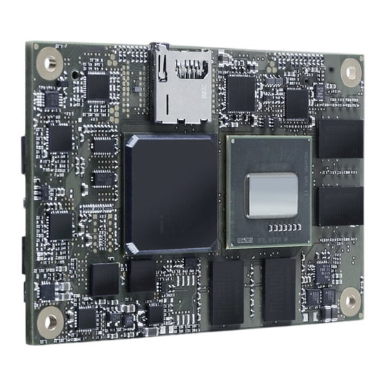
Product Description The credit card size (55mm x 84 mm) COM Express® mini SFF COM, COMe-mTT10, featuring an Intel® Atom™ processor E6xx and is designed according to the PICMG COM Express® R.2.0 pin-out Type 10 specification. The COMe-mTTi10 family is designed with industrial-grade components that are fully functional even at the extended temperature range (E2) from -40 to +85°C, special build versions for commercial temperature are available as well. -
Page 8: Com Express® Documentation
COM Express® Documentation This product manual serves as one of three principal references for a COM Express® design. It documents the specifications and features of COMe-mTT10. Additional references are are available from your Kontron Support or from PICMG®: » The COM Express® Specification defines the COM Express® module form factor, pin-out, and signals. This document is available from the PIGMG website by filling out the order form. -
Page 9: Product Specification
The COM Express® mini sized Computer-on-Module COMe-mTT10 (NTC1) follows pin-out Type 10 and is compatible to PICMG specification COM.0 Rev 2.0. The COMe-mTT10, based on Intel's Queens Bay platform, is available in different variants to cover the demand of different performance, price and power: Commercial grade modules (0°C to 60°C operating), COMe-mTTc10... - Page 10 Cooling & Mounting 34003-0000-99-0 HSP COMe-mTT10 thread (11mm) 34003-0000-99-1 HSP COMe-mTT10 through (11mm) 34003-0000-99-2 HSP COMe-mTT10 slim thread (6.5mm) 34003-0000-99-3 HSP COMe-mTT10 slim though (6.5mm) 34003-0000-99-0CO1 HSK COMe-mTT10 slim passive thread 34099-0000-99-0 COMe mini Active Uni Cooler (for CPUs up to 10W)
-
Page 11: Functional Specification
COMe-mTT10 / Product Specification Functional Specification Processor The Intel® ATOM™ (Tunnel Creek) CPU family supports: » Intel® Hyper-Threading Technology » Intel® Virtualization Technology (VT-x) » Idle States » Enhanced Intel SpeedStep® Technology » Thermal Monitoring Technologies » Execute Disable Bit... - Page 12 COMe-mTT10 / Product Specification Display Interfaces Discrete Graphics Digital Display Interface DDI1 SDVOB Digital Display Interface DDI2 Digital Display Interface DDI3 Maximum Resolution on DDI 1920x1080 Platform Controller Hub The 90nm Intel Platform Controller Hub EG20T (Topcliff) supports: » PCI Express Revision 1.0 »...
- Page 13 COMe-mTT10 / Product Specification Misc Interfaces and Features Audio HD Audio Onboard Hardware Monitor WINBOND W83L771W or optional LM87 Trusted Platform Module* Infineon TPM 1.2 SLB9635TT optional Miscellaneous 1x CAN optional / 2x UART *The TPM Option is only valid for commercial temperature grade modules...
- Page 14 COMe-mTT10 / Product Specification Supported Operating Systems The COMe-mTT10 currently supports: » Microsoft Windows 7 » Microsoft Windows Embedded Standard 7 (WES7) » Microsoft Windows Embedded Compact 7 (WEC7) » Microsoft Windows embedded CE 6.0 » Microsoft Windows XP » Microsoft Windows XPembedded »...
-
Page 15: Block Diagram
COMe-mTT10 / Product Specification Block Diagram... -
Page 16: Electrical Specification
» Maximum 100 mV peak to peak 0 – 20 MHz 3.4.4 Power Consumption The maximum Power Consumption of the different COMe-mTT10 variants is 5.2 - 7.5W (100% CPU load on all cores; 90°C CPU temperature). Further information with detailed measurements are available in Application Note KEMAP054 available EMD Customer... -
Page 17: Atx Mode
COMe-mTT10 / Product Specification 3.4.5 ATX Mode By connecting an ATX power supply with VCC and 5VSB, PWR_OK is set to low level and VCC is off. Press the Power Button to enable the ATX PSU setting PWR_OK to high level and powering on VCC. The ATX PSU is controlled by the PS_ON# signal which is generated by SUS_S3# via inversion. -
Page 18: Power Control
COMe-mTT10 / Product Specification Power Control Power Supply The COMe-mTT10 supports a power input from 4.75 - 14V. The supply voltage is applied through the VCC pins (VCC) of the module connector. Power Button (PWRBTN#) The power button (Pin B12) is available through the module connector described in the pinout list. To start the module via Power Button the PWRBTN# signal must be at least 50ms (50ms ≤... -
Page 19: Environmental Specification
COMe-mTT10 / Product Specification Environmental Specification 3.6.1 Temperature Specification General Specification Operating Non-operating Commercial grade 0°C to +60°C -30°C to +85°C Extended (E1) -25°C to +75°C -30°C to +85°C Industrial grade (E2) -40°C to +85°C -40°C to +85°C Standard modules are available for commercial grade temperature range. Please see... -
Page 20: Standards And Certifications
COMe-mTT10 / Product Specification Standards and Certifications RoHS The COMe-mTT10 is compliant to the directive 2002/95/EC on the restriction of the use of certain hazardous substances (RoHS) in electrical and electronic equipment. CE marking The COMe-mTT10 is CE marked according to Low Voltage Directive 2006/95/EC – Test standard EN60950 Component Recognition UL 60950-1 The COM Express®... - Page 21 The COM Express® mini form factor Computer-on-Modules successfully passed shock and vibration tests according to » IEC/EN 60068-2-6 (Non operating Vibration, sinusoidal, 10Hz-4000Hz, +/-0.15mm, 2g) » IEC/EN 60068-2-27 (Non operating Shock Test, half-sinusoidal, 11ms, 15g) Validated in Kontron reference housing for EMC the COMe-mTT10 follows the requirements for electromagnetic compatibility standards » EN55022...
-
Page 22: Mtbf
Estimated RTC battery life (as opposed to battery failures) is not accounted for in the above figures and need to be considered for separately. Battery life depends on both temperature and operating conditions. When the Kontron unit has external power; the only battery drain is from leakage paths. -
Page 23: Mechanical Specification
COMe-mTT10 / Product Specification Mechanical Specification 3.9.1 Module Dimension » 55mm x 84mm (±0.2mm) 3.9.2 Height on Top » Maximum approx. 3.5mm (withouth printed circuit board) » Height is depending on (optional) CPU cooler / heat spreader 3.9.3 Height on Bottom »... -
Page 24: Thermal Management
Thermal Management A heatspreader plate assembly is available from Kontron Europe GmbH for the COMe-mTT10. The heatspreader plate on top of this assembly is NOT a heat sink. It works as a COM Express®-standard thermal interface to use with a heat sink or other cooling device. -
Page 25: Features And Interfaces
Onboard SSD The COMe-mTT10 features an onboard Greenliant SATA NAND flash drive with capacities of 2 to 8GB SLC, 2 to 32GB MLC (SATA). Due to performance and longevity reasons standard variants with onboard flash use SLC type only. The following... -
Page 26: S5 Eco Mode
COMe-mTT10 / Features and Interfaces S5 Eco Mode Kontron’s new high-efficient power-off state S5 Eco enables lowest power-consumption in soft-off state – less than 1 mA compared to the regular S5 state this means a reduction by at least factor 200! In the “normal”... -
Page 27: Lpc
LPC. This leads to limitations for ISA bus and SIO (standard I/O´s like Floppy or LPT interfaces) implementations. All Kontron COM Express® Computer-on-Modules imply BIOS support for following external baseboard LPC Super I/O controller features for the Winbond/Nuvoton 5V 83627HF/G and 3.3V 83627DHG-P:... -
Page 28: Serial Peripheral Interface (Spi)
The SPI interface can only be used with a SPI flash device to boot from external BIOS on the baseboard. SPI boot The COMe-mTT10 supports boot from an external SPI Flash. It can be configured by pin A34 (BIOS_DIS#0) and pin B88 (BIOS_DIS1#) in following configuration: BIOS_DIS0#... -
Page 29: M.a.r.s
COMe-mTT10 / Features and Interfaces M.A.R.S. The Smart Battery implementation for Kontron Computer-on-Modules called Mobile Application for Rechargeable Systems is a BIOS extension for external Smart Battery Manager or Charger. It includes support for SMBus charger/selector (e.g. Linear Technology LTC1760 Dual Smart Battery System Manager) and provides ACPI compatibility to report battery information to the Operating System. -
Page 30: Uart
COMe-mTT10 / Features and Interfaces UART The COMe-mTT10 supports two Serial RX/TX only UART Ports defined in COM Express® specification on Pins A98/A99 for UART0 and Pins A101/A102 for UART1. The 16550 compatible UARTs are provided from the - and resources are subordinated to other UARTS e.g. -
Page 31: Can
COMe-mTT10 / Features and Interfaces The COMe-mTT10 optionally supports the EG20T implemented CAN interface as defined in COM Express® specification on Pins Pins A101/A102 instead of UART1. To connect the CAN interface from the module to the CAN bus, it is necessary to add transceiver hardware on the Carrier Board. -
Page 32: Fast I2C
COMe-mTT10 / Features and Interfaces Fast I2C The COMe-mTT10 supports a CPLD implemented LPC to I2C bridge using the WISHBONE I2C Master Core provided from opencores.org. The I2C Interface supports transfer rates up to 40kB/s and can be configured in Setup Specification for external I2C: »... -
Page 33: Keapi
4.10 KeAPI The Kontron embedded API (KeAPI) is an extension of the PICMG EAPI mainly with additional remote functionality. It consists of hardware drivers providing access to features like Watchdog, I2C Bus or GPIO and a QT based user interface KEAPI GUI. -
Page 34: Eapi, Jida & Pld Driver
4.11 EAPI, JIDA & PLD Driver K-Station 2 including the Kontron PLD / Board Driver for new generation modules is a replacement for former JIDA16/JIDA32 BIOS implementations. It consists of hardware drivers providing access to features like Watchdog, I2C Bus or GPIO implemented in the onboard Programmable Logic Device (CPLD). -
Page 35: K-Station 2
Based on the JIDA32 interface users can implement advanced board functionality in their application. As an example utility Kontron provides K-Station 2 for 32 and 64bit Windows XP, Vista or 7. K-Station 2 is a summary of command line utilities (Shell Tools) for easy access to JIDA32 interface provide by the PLD Board Driver. Second part of K-Station is a JAVA based example GUI which gives a view an all available features using the Shell Tools. -
Page 36: Gpio - General Purpose Input And Output
COMe-mTT10 / Features and Interfaces 4.13 GPIO - General Purpose Input and Output The COMe-mTT10 offers 4 General Purpose Input (GPI) pins and 4 General Purpose Output (GPO) pins. On a 3.3V level digital in- and outputs are available. Signal... -
Page 37: Dual Staged Watchdog Timer
“feeding the watchdog” or “triggering the watchdog”). The intention is to bring the system back from the nonresponsive state into normal operation. The COMe-mTT10 offers a watchdog which works with two stages that can be programmed independently and used one by one. -
Page 38: Speedstep Technology
COMe-mTT10 / Features and Interfaces 4.15 Speedstep Technology The Intel® processors offers the Intel® Enhanced SpeedStep™ technology that automatically switches between maximum performance mode and battery-optimized mode, depending on the needs of the application being run. It let you customize high performance computing on your applications. When powered by a battery or running in idle mode, the processor drops to lower frequencies (by changing the CPU ratios) and voltage, conserving battery life while maintaining a high level of performance. -
Page 39: C-States
COMe-mTT10 / Features and Interfaces 4.16 C-States New generation platforms include power saving features like SuperLFM, EIST (P-States) or C-States in O/S idle mode. Activated C-States are able to dramatically decrease power consumption in idle mode by reducing the Core Voltage or switching of parts of the CPU Core, the Core Clocks or the CPU Cache. -
Page 40: Hyper Threading
COMe-mTT10 / Features and Interfaces 4.17 Hyper Threading Hyper Threading (officially termed Hyper Threading Technology or HTT) is an Intel®-proprietary technology used to improve parallelization of computations performed on PC´s. Hyper-Threading works by duplicating certain sections of the processor—those that store the architectural state but not duplicating the main execution resources. This allows a Hyper- Threading equipped processor to pretend to be two “logical”... -
Page 41: Acpi Suspend Modes And Resume Events
COMe-mTT10 / Features and Interfaces 4.18 ACPI Suspend Modes and Resume Events The COMe-mTT10 supports the S3 state (=Save to Ram). S4 (=Save to Disk) is not supported by the BIOS (S4_BIOS) but S4_OS is supported by the following operating systems: » Windows XP »... -
Page 42: Usb
COMe-mTT10 / Features and Interfaces 4.19 The available USB configuration of the COMe-mTT10 module is described in the following table: COM Express Port EG20 Port Comment USB0 USB0 USB1 USB1 USB2 USB2 USB3 USB3 USB4 USB4 USB5 USB5 USB6 USB5... -
Page 43: Sdio
COMe-mTT10 / Features and Interfaces 4.20 SDIO The SD card standard is a standard for removable memory storages designed and licensed by the SD Card Association (http://sdcard.org). The card form factor, electrical interface, and protocol are all part of the SD Card specification. The Intel®... - Page 44 COMe-mTT10 / Features and Interfaces onboard microSD connector J3 Pin name Signal DAT2 SDIO1_DAT0 CD/DAT3 SDIO1_DAT3 SDIO1_CMD 3.3V S0 SDIO1_CLK VSS2 DAT0 SDIO1_DAT1 DAT1 SDIO1_DAT2 SWITCH1 SDIO1_CD# SWITCH2 SHIELD1 SHIELD2 SHIELD3 SHIELD4 SHIELD5 - The SD_CMD line needs a pull-up resistor that can vary depending on the length of the electrical paths (typical from 10kOhm to 100kOhm) - The maximum length for SDIO signals on the baseboard should be 80mm.
-
Page 45: System Resources
COMe-mTT10 / System Resources 5 System Resources Interrupt Request (IRQ) Lines 5.1.1 In 8259 PIC mode IRQ # Used For Available Comment Timer0 Keyboard Cascade External SIO - COM2 Yes (No) Note (1) External SIO - COM1 Yes (No) Note (1) -
Page 46: In Apic Mode
COMe-mTT10 / System Resources 5.1.2 In APIC mode IRQ # Used For Available Comment Timer0 Keyboard Cascade External SIO - COM2 Yes (No) Note (1) External SIO - COM1 Yes (No) Note (1) for PCI Dynamic (BIOS default) for PCI... -
Page 47: Memory Area
COMe-mTT10 / System Resources Memory Area The first 640 kB of DRAM are used as main memory. Using DOS, you can address 1 MB of memory directly. Memory area above 1 MB (high memory, extended memory) is accessed under DOS via special drivers such as HIMEM.SYS and EMM386.EXE, which are part of the operating system. -
Page 48: Peripheral Component Interconnect (Pci) Devices
COMe-mTT10 / System Resources Peripheral Component Interconnect (PCI) Devices All devices follow the Peripheral Component Interconnect 2.3 (PCI 2.3) respectivily the PCI Express Base 1.0a specification. The BIOS and OS control memory and I/O resources. Please see the PCI 2.3 specification for details. -
Page 49: Jili I2C Bus
COMe-mTT10 / System Resources JILI I2C Bus I2C Address Used For Available Comment JILI-EEPROM EEPROM for JILI Data SDVO I2C Bus I2C Address Used For Available Comment System Management (SM) Bus Address Device Comment SMART_CHARGER Not to be used with any SM bus deivce except a charger... -
Page 50: Pinout List
COMe-mTT10 / System Resources Pinout List 5.9.1 General Signal Description Type Description Bi-directional 3,3 V IO-Signal I/O-3,3 I/O-5T Bi-dir. 3,3V I/O (5V Tolerance) I/O-5 Bi-directional 5V I/O-Signal I-3,3 3,3V Input I/OD Bi-directional Input/Output Open Drain 3,3V Input (5V Tolerance) I-5T... -
Page 51: Connector X1A Row A
COMe-mTT10 / System Resources 5.9.2 Connector X1A Row A Signal Description Type Termination Comment GND_1 Power Ground GBE0_MDI3- Ethernet Receive Data- DP-I GBE0_MDI3+ Ethernet Receive Data+ DP-I GBE0_LINK100# Ethernet Speed LED 100Mbps GBE0_LINK1000# Ethernet Speed LED 1000Mbps GBE0_MDI2- Ethernet Receive Data-... - Page 52 COMe-mTT10 / System Resources PCIE_TX2+ PCIe lane #2 Transmit+ DP-O PD ~50R(PU @ reset) in PCIE_TX2- PCIe lane #2 Transmit- DP-O PD ~50R in TNC SDIO_D1 / GPI1 SDIO#0 Data1 / General Purpose Input 1 I/O-3.3 PU 10k/100k to V3.3_S0...
-
Page 53: Connector X1A Row B
COMe-mTT10 / System Resources 5.9.3 Connector X1A Row B Signal Description Type Termination Comment GND_16 Power Ground GBE0_ACT# Ethernet Activity LED LPC_FRAME# LPC Frame Indicator O-3.3 LPC_AD0 LPC Address / Data Bus IO-3.3 PU 100k LPC_AD1 LPC Address / Data Bus IO-3.3... - Page 54 COMe-mTT10 / System Resources PCIE_RX2+ PCIe lane #2 Receive+ DP-I PD ~50R(PU @ reset) in PCIE_RX2- PCIe lane #2 Receive- DP-I PD ~50R(PU @ reset) in SDIO_CD# / GPO3 SDIO#0 CardDetect / General Purpose Output 3 I-3.3 PU 10k V3.3V_S0 / PD 100k -...
-
Page 55: Bios Operation
» BIOS Date: mm/dd/yyyy hh:mm:ss » BIOS Version: NTC1RXXX BIOS Update Kontron provides continous BIOS updates for Computer-on-Modules. The updates are provided for download on http://emdcustomersection.kontron.com with a detailed change description within the according Product Change Notification (PCN). Please register for EMD Customer Section to get access to BIOS downloads and PCN service. - Page 56 COMe-mTT10 / BIOS Operation Backup the BIOS / Create a BIOS with custom defaults: » Change your BIOS settings according your needs » Save and Exit Setup with option “Save as User Defaults”. Your customized settings are now stored inside the flash in a second area additional to the manufacturer defaults »...
-
Page 57: Setup Guide
COMe-mTT10 / BIOS Operation Setup Guide The Aptio Setup Utility changes system behavior by modifying the Firmware configuration. The setup program uses a number of menus to make changes and turn features on or off. Functional keystrokes in POST: Function... - Page 58 COMe-mTT10 / BIOS Operation Menu Bar The menu bar at the top of the window lists different menus. Use the left/right arrow keys to make a selection. Legend Bar Use the keys listed in the legend bar on the bottom to make your selections or exit the current menu. The table below describes the legend keys and their alternates.
-
Page 59: Bios Setup
COMe-mTT10 / BIOS Operation BIOS Setup 6.4.1 Main Feature Options Description System Language English Choose the system default language System Date [mm/dd/yyyy] Set the Date. Use 'Tab' to switch between Date elements System Time [hh:mm:ss] Set the Time. Use 'Tab' to switch between Time... - Page 60 COMe-mTT10 / BIOS Operation Platform Information...
-
Page 61: Advanced
COMe-mTT10 / BIOS Operation 6.4.2 Advanced... - Page 62 COMe-mTT10 / BIOS Operation PCI Subsystem Settings Feature Options Description PCI ROM Priority Legacy ROM In case of multiple Option ROMs (Legacy and EFI EFI Compatible ROM Compatible), specifies what PCI Option ROM to launch PCI Latency Timer 32 … 248 PCI Bus Clocks...
- Page 63 COMe-mTT10 / BIOS Operation PCI Express Settings Feature Options Description Relaxed Ordering Disabled Enables or Disables PCI Express Device Relaxed Ordering Enabled Extended Tag Disabled If Enabled allows device to use 8-bit Tag field as a requester Enabled No Snoop...
- Page 64 COMe-mTT10 / BIOS Operation ACPI Settings Feature Options Description Enable ACPI Auto Congiguration Disabled Enables or Disables BIOS ACPI Auto Configuration Enabled Enable Hibernation Disabled Enables or Disables System ability to Hibernate (OS/S4 Sleep State). This option may be not effective with Enabled some OS.
- Page 65 COMe-mTT10 / BIOS Operation Thermal Configuration Feature Options Description Critical Trip Point This value controls the temperature of the ACPI Critical Trip Point - the point in which the OS will shut the 30°C system off. Note: 100°C is the Plan Of Record (POR) for …...
- Page 66 COMe-mTT10 / BIOS Operation Passive Cooling The ACPI OS assesses the optimum CPU performance change necessary to lower the temperature using the following equation ΔP[%] = TC1(Tn-Tn-1) + TC2(Tn-Tt) ΔP is the performance delta, Tt is the target temperature = passive cooling trip point. The two coefficients TC1 and TC2 and the sampling period TSP are hardware dependent constants the end user must supply.
- Page 67 COMe-mTT10 / BIOS Operation ACPI Wake Event Configuration Feature Options Description Wake On Lan Disable Enable / Disable WOL Enable Wake On USB Disable Enable / Disable Wake On USB. This works only on ports Enable powered with standby voltage...
- Page 68 COMe-mTT10 / BIOS Operation CPU Configuration Feature Options Description Intel SpeedStep Disabled Enables/Disables the Intel Speedstep Technology (E)IST Enabled Hyper-Threading Disabled Enables/Disables the Intel® Hyper Threading Enabled Technology HTT Execute Disable Bit Disabled XD can prevent certain classes of malicious buffer...
- Page 69 COMe-mTT10 / BIOS Operation Miscellaneous Feature Options Description S5 Eco Disabled Reduce supply current in Soft Off State S5 to less than 1mA. If enabled, power button is the only wakeup Enabled source in S5. See chapter S5 Eco for more details...
- Page 70 COMe-mTT10 / BIOS Operation Trusted Computing Feature Options Description TPM Support Disabled Enables or Disables TPM support. O.S. will not show Enabled TPM. Reset of platform is required TPM State Disabled Turn TPM On/Off. NOTE: Your Computer will reboot to...
- Page 71 COMe-mTT10 / BIOS Operation Clock Control Feature Options Description Spread Spectrum Disabled Enable/Disable Spread Spectrum Enabled...
- Page 72 COMe-mTT10 / BIOS Operation Watchdog Feature Options Description Auto-reload Disabled Enable automatic reload of watchdog timers on timeout Enabled Global Lock Disabled If set to enabled, all Watchdog registers (except WD_KICK) become read only until the board is reset Enabled...
- Page 73 COMe-mTT10 / BIOS Operation Smart Battery Configuration Feature Options Description M.A.R.S. Disabled Preset M.A.R.S. Smart Battery System mode. System AUTO must be restarted to reflect mode changes Charger Manager SMBAlert Disabled Enable/Disable SMBAlert# handling in chipset Enabled...
- Page 74 COMe-mTT10 / BIOS Operation Battery Information...
- Page 75 COMe-mTT10 / BIOS Operation SMBus Speed Feature Options Description SMBus Speed 10kHz Select SMBus Speed 50kHz 100kHz...
- Page 76 COMe-mTT10 / BIOS Operation Onboard I2C Speed Feature Options Description Onboard I2C Speed 1kHz Select Onboard I2C Bus Speed in kHz, min. 1kHz, max. 10kHz 400kHz 50kHz 100kHz 200kHz 400kHz...
- Page 77 COMe-mTT10 / BIOS Operation USB Configuration Feature Options Description Legacy USB Support Enabled Enables Legacy USB support. AUTO option disables legacy support if no USB devices are connected. Disabled AUTO DISABLE option will keep USB devices available only for EFI applications.
- Page 78 COMe-mTT10 / BIOS Operation SDIO Configuration Feature Options Description SDIO Access Mode Auto Auto Option: Access SD device in DMA mode if controller supports it, otherwise in PIO mode. DMA Option: Access SD device in DMA mode, PIO Option: Access SD device in...
- Page 79 COMe-mTT10 / BIOS Operation Module H/W Monitor Hardware Monitor measurements and configuration for the onboard WINBOND W83L771W or optional LM87. Feature Value/Options Description Local Temperature xx°C Shows the internal temperature of onboard HWM CPU Temperature xx°C Shows the measured temperature of the CPU Diode with...
- Page 80 Super IO Configuration This setup option is available if a LPC SuperI/O Nuvoton 83627 is present on the baseboard. By default the COMe-mTT10 supports the legacy interfaces of a 5V 83627HF(J) or 3.3V 83627DHG-P on external LPC. The hardware monitor is not...
- Page 81 COMe-mTT10 / BIOS Operation Serial Port 0 Configuration Feature Options Description Serial Port Disabled Enable or Disable Serial Port (COM) 0 Enabled Change Settings AUTO Select an optimal setting for SuperIO device. IO=3F8h; IRQ=4; IO=3F8h, IRQ=3,4,5,6,7,10,11,12; IO=2F8h, IRQ=3,4,5,6,7,10,11,12; IO=3E8h, IRQ=3,4,5,6,7,10,11,12;...
- Page 82 COMe-mTT10 / BIOS Operation Parallel Port Configuration Feature Options Description Parallel Port Disabled Enable or Disable the Parallel Port (LPT/LPTE) Enabled Change Settings AUTO Select an optimal setting for SuperIO device. IO=378h; IRQ=5; IO=378h, IRQ=5,6,7,10,11,12; IO=278h, IRQ=5,6,7,10,11,12; IO=3BCh, IRQ=5,6,7,10,11,12; IO=378h;...
- Page 83 COMe-mTT10 / BIOS Operation Serial Port Console Redirection Feature Options Description Console Redirection Disabled Enable/Disable Serial Port COM0 Console Redirection Enabled Console Redirection Disabled Enable/Disable Serial Port COM1 Console Redirection Enabled Console Redirection Disabled Enable/Disable Serial Port COM2 Console Redirection...
- Page 84 COMe-mTT10 / BIOS Operation COM0-3 Console Redirection Settings Feature Options Description Terminal Type VT100 VT100: ASCII char set. VT100+ VT100+: Extends VT100 to support color, function keys, VT_UTF8 etc. ANSI VT-UTF8: Uses UTF8 encoding to map Unicode chars onto 1 or more bytes ANSI: Extended ASCII char set.
- Page 85 COMe-mTT10 / BIOS Operation Out-of-Band Management Port Console Redirection Settings Feature Options Description Out-of-Band Mgmt Port COM0 Microsoft Windows Emergency Management Services COM1 (EMS) allows for remote management of a Windows COM2 (PCI Bus10,Dev10,Func2) Server OS through a serial port...
- Page 86 COMe-mTT10 / BIOS Operation 6.4.3 Chipset...
- Page 87 COMe-mTT10 / BIOS Operation North Bridge Chipset Configuration Feature Options Description IGD Mode Select Disabled Select the amount of system memory used by the Enabled, 1MB Integrated Graphics Device Enabled, 4MB Enabled, 8MB Enabled, 16MB Enabled, 32MB Enabled, 48MB Enabled, 64MB...
- Page 88 COMe-mTT10 / BIOS Operation Due to space limitations due to simultaneous SDVO and LVDS support only one manual LVDS resolutions is supported in setup. With Intel® EMGD you can change this resolution and create a new VideoBIOS according your requirements. Please contact your local support to...
- Page 89 COMe-mTT10 / BIOS Operation South Bridge Chipset Configuration Feature Options Description Audio Controller Disabled Control Detection of the High definition audio (Azalia) Enabled device. Disabled = HDaudio will be unconditionally Auto disabled. Enabled = HDaudio will be unconditionally enabled. Auto = HDaudio will be enabled if present,...
-
Page 90: Chipset
COMe-mTT10 / BIOS Operation PCI Express Ports Configuration Feature Options Description BIOS Hot-Plug Support Disabled If ENABLED allows BIOS build in Hot-Plug Support. Use Enabled this feature if OS does not support PCI Express and SHPC hot-plug natively I/O Resources Padding... - Page 91 COMe-mTT10 / BIOS Operation PCI Express Root Port 0/1/2 Feature Options Description PCI Express Root Port Disabled Control the PCI Express Root Port Enabled...
- Page 92 COMe-mTT10 / BIOS Operation PPM Config Feature Options Description C-State POPUP Disabled Enable/Disable C-state POPUP Enabled...
-
Page 93: Boot
COMe-mTT10 / BIOS Operation 6.4.4 Boot Feature Options Description Setup Prompt Timeout Number of seconds to wait for setup activation key. 65535 (0xFFFF) means idefinite waiting. 0 means no wait (not recommended) Bootup NumLock State Select the keyboard NumLock state... - Page 94 COMe-mTT10 / BIOS Operation Boot Option Priority By default, AMI APTIO uses following boot priority if at least on device of a group is connected: » Boot Option #1: Prio 1 Hard Disk » Boot Option #2: Built-in EFI Shell »...
-
Page 95: Security
COMe-mTT10 / BIOS Operation 6.4.5 Security Feature Options Description Administrator Password Set the Administrator Password for Setup Access User Password Set User Password... -
Page 96: Save & Exit
COMe-mTT10 / BIOS Operation 6.4.6 Save & Exit Feature Options Description Save Changes and Exit Exit system setup after saving the changes Discard Changes and Exit Exit system setup without saving any changes Save Changes and Reset Reset system after saving the changes... - Page 97 COMe-mTT10 / BIOS Operation Corporate Offices Europe, Middle East & Africa North America Asia Pacific Oskar-von-Miller-Str. 1 14118 Stowe Drive 17 Building,Block #1,ABP. 85386 Eching/Munich Poway, CA 92064-7147 188 Southern West 4th Ring Germany Beijing 100070, P.R.China Tel.: +49 (0)8165/ 77 777 Tel.: +1 888 294 4558...
Need help?
Do you have a question about the COMe-mTT10 and is the answer not in the manual?
Questions and answers