
Subscribe to Our Youtube Channel
Related Manuals for YASKAWA SLIO IM 060


Summary of Contents for YASKAWA SLIO IM 060
- Page 1 System SLIO IM | 06x-1xA0x | Manual HB300 | IM | 06x-1xA0x | en | 24-02 Interface module Line extension - IM 06x...
- Page 2 YASKAWA Europe GmbH Philipp-Reis-Str. 6 65795 Hattersheim Germany Tel.: +49 6196 569-300 Fax: +49 6196 569-398 Email: info@yaskawa.eu Internet: www.yaskawa.eu.com 06x-1xA00_000_IM 06x,5,EN - © 2024...
-
Page 3: Table Of Contents
Copyright © YASKAWA Europe GmbH........ - Page 4 Table of contents System SLIO 3.6.3 061-1BA00 Line extension slave - version 1..........51 3.6.4 061-1BA00 Line extension slave - version 2.
-
Page 5: General
Copyright © YASKAWA Europe GmbH All Rights Reserved This document contains proprietary information of Yaskawa and is not to be disclosed or used except in accordance with applicable agreements. This material is protected by copyright laws. It may not be reproduced, distributed, or... -
Page 6: About This Manual
About this manual Technical support Contact your local representative of YASKAWA Europe GmbH if you encounter problems or have questions regarding the product. If such a location is not available, you can reach the Yaskawa customer service via the following contact: YASKAWA Europe GmbH, European Headquarters, Philipp-Reis-Str. -
Page 7: Safety Information
General System SLIO Safety information Safety information Applications conforming with The system is constructed and produced for: specifications ■ communication and process control ■ general control and automation tasks ■ industrial applications ■ operation within the environmental conditions specified in the technical data ■... -
Page 8: Basics And Mounting
Basics and mounting System SLIO Safety notes for the user Basics and mounting Safety notes for the user DANGER Protection against dangerous voltages − When using System SLIO modules, the user must be protected from touching hazardous voltage. − You must therefore create an insulation concept for your system that includes safe separation of the potential areas of ELV and hazardous voltage. -
Page 9: System Conception
Basics and mounting System SLIO System conception > Overview System conception 2.2.1 Overview The System SLIO is a modular automation system for assembly on a 35mm mounting rail. By means of the periphery modules with 2, 4, 8 and 16 channels this system may properly be adapted matching to your automation tasks. -
Page 10: Components
Power modules ■ Accessories CAUTION Only Yaskawa modules may be combined. A mixed operation with third-party modules is not allowed! CPU 01xC With the CPU 01xC electronic, input/output components and power supply are integrated to one casing. In addition, up to 64 periphery modules of the System SLIO can be con- nected to the backplane bus. - Page 11 Please note that some modules do not support line extensions due to the system. For more information, please refer to the compatibility list. This can be found in the ‘Download Center’ of www.yaskawa.eu.com under ‘System SLIO Compatibility list’. Periphery modules...
- Page 12 Basics and mounting System SLIO System conception > Components Terminal module The terminal module serves to carry the electronic module, contains the backplane bus with power supply for the electronic, the DC 24V power section supply and the staircase- shaped terminal for wiring. Additionally the terminal module has a locking system for fixing at a mounting rail.
-
Page 13: Accessories
Basics and mounting System SLIO System conception > Accessories Terminal block The terminal block provides the electrical interface for the signalling and supplies lines of the module. When mounting the terminal block, it is attached to the bottom of the elec- tronic unit and turned towards the electronic unit until it clicks into place. - Page 14 Basics and mounting System SLIO System conception > Accessories Bus cover With each head module, to protect the backplane bus connectors, there is a mounted bus cover in the scope of delivery. You have to remove the bus cover of the head module before mounting a System SLIO module.
-
Page 15: Hardware Revision
Basics and mounting System SLIO Dimensions 2.2.4 Hardware revision ■ Hardware revision on the The hardware revision is printed on every System SLIO module. front ■ Since a System SLIO 8x periphery module consists of a terminal and electronic module, you will find a hardware revision printed on each of them. ■... - Page 16 Basics and mounting System SLIO Dimensions Dimensions CPU 01x Dimensions bus coupler and line extension slave Dimensions line extension master HB300 | IM | 06x-1xA0x | en | 24-02...
-
Page 17: Mounting Line Extension
Basics and mounting System SLIO Mounting line extension Dimension periphery module Dimensions electronic module Dimensions in mm Mounting line extension − By means of the line extension 1 line of modules can be divided to maximum 5 lines. − For each line extension the maximum number of pluggable modules at the System SLIO bus is decreased: −... -
Page 18: Mounting Line Extension Master
Basics and mounting System SLIO Mounting line extension > Mounting line extension master 2.4.1 Mounting line extension master Proceeding There is a locking lever at the top side of the line extension master. For mounting and demounting this locking lever is to be turned upwards until this engages. Turn the locking lever upwards. -
Page 19: Mounting Line Extension Slave
Basics and mounting System SLIO Mounting line extension > Mounting line extension slave 2.4.2 Mounting line extension slave Proceeding Mount the mounting rail! Please consider that a clearance from the middle of the mounting rail of at least 80mm above and 60mm below, respectively 80mm by deployment of shield bus carriers, exist. - Page 20 Basics and mounting System SLIO Mounting line extension > Mounting line extension slave Mounting of the periphery Before mounting the periphery modules you have to remove the bus cover at the modules right side of the line extension slave by pulling it forward. Keep the cover for later mounting.
-
Page 21: Wiring Line Extension
Basics and mounting System SLIO Wiring line extension > Wiring line extension slave Wiring line extension 2.5.1 Wiring line extension master Since the line extension master is supplied via the power section supply of the backplane bus, an additional wiring is not required. 2.5.2 Wiring line extension slave Terminal module terminals... - Page 22 Basics and mounting System SLIO Wiring line extension > Wiring line extension slave Standard wiring (1) DC 24V for power section supply I/O area (max. 10A) (2) DC 24V for electronic section supply line extension slave and I/O area. PM - Power module For wires with a core cross-section of 0.08mm up to 1.5mm Pos.
- Page 23 Basics and mounting System SLIO Wiring line extension > Wiring line extension slave ■ Fusing The power section supply is to be externally protected with a fuse, which corresponds to the maximum current. This means max. 10A is to be protected with a 10A fuse (fast) respectively by a line circuit breaker 10A characteristics Z! ■...
- Page 24 Basics and mounting System SLIO Wiring line extension > Wiring line extension slave Shield attachment Each System SLIO 8x periphery module has a carrier hole for the shield bus carrier. Push the shield bus carrier, until they engage into the module. With a flat mounting rail for adaptation to a flat mounting rail you may remove the spacer of the shield bus carrier.
-
Page 25: Line Extension - Connection Cable
Line extension - connection cable Cabling CAUTION When 06x-1xA00 used - version 1: − Please use connection cables from Yaskawa for connection. The use of normal Ethernet cable can cause damage! − The connection cable must not exceed the maximum length of 2m. −... -
Page 26: Demounting Line Extension
Basics and mounting System SLIO Demounting line extension > Demounting line extension master Demounting line extension 2.6.1 Demounting line extension master Proceeding Power-off your system. Remove if exists the connection cable at line extension master. Turn the locking lever of the line extension master to be exchanged upwards. Pull the line extension master forward. -
Page 27: Demounting Line Extension Slave
Basics and mounting System SLIO Demounting line extension > Demounting line extension slave 2.6.2 Demounting line extension slave Proceeding CAUTION Line extension interface and power module of the line extension slave may not be separated! Here you may only exchange the electronic module! Power-off your system. - Page 28 Basics and mounting System SLIO Demounting line extension > Demounting line extension slave Turn all the locking lever downward, again. Plug again the electronic module, which you have removed before. Plug again the connection cable. �� Now you can bring your system back into operation. HB300 | IM | 06x-1xA0x | en | 24-02...
-
Page 29: Trouble Shooting - Leds
Basics and mounting System SLIO Trouble shooting - LEDs Trouble shooting - LEDs General Each module has the LEDs RUN and MF on its front side. Errors or incorrect modules may be located by means of these LEDs. In the following illustrations flashing LEDs are marked by ☼. Sum current of the electronic power supply exceeded... -
Page 30: Industrial Security And Installation Guidelines
Industrial security in information technology Latest version This chapter can also be found as a guide ‘Industrial IT Security’ in the ‘Download Center’ of www.yaskawa.eu.com Hazards The topic of data security and access protection has become increasingly important in the industrial environment. The increased networking of entire industrial systems to the network levels within the company together with the functions of remote maintenance have all served to increase vulnerability. - Page 31 Basics and mounting System SLIO Industrial security and installation guidelines > Industrial security in information technology 2.8.1.1 Protection of hardware and applications ■ Precautions Do not integrate any components or systems into public networks. – Use VPN "Virtual Private Networks" for use in public networks. This allows you to control and filter the data traffic accordingly.
-
Page 32: Installation Guidelines
Basics and mounting System SLIO Industrial security and installation guidelines > Installation guidelines 2.8.1.2 Protection of PC-based software Precautions Since PC-based software is used for programming, configuration and monitoring, it can also be used to manipulate entire systems or individual components. Particular caution is required here! ■... - Page 33 Basics and mounting System SLIO Industrial security and installation guidelines > Installation guidelines Possible interference Electromagnetic interferences may interfere your control via different ways: causes ■ Electromagnetic fields (RF coupling) ■ Magnetic fields with power frequency ■ Bus system ■ Power supply ■...
- Page 34 Basics and mounting System SLIO Industrial security and installation guidelines > Installation guidelines ■ Create a homogeneous reference potential and ground all electrical operating supplies when possible. – Please take care for the targeted employment of the grounding actions. The grounding of the PLC serves for protection and functionality activity.
-
Page 35: General Data For The System Slio
Basics and mounting System SLIO General data for the System SLIO General data for the System SLIO Conformity and approval Conformity 2014/35/EU Low Voltage Directive 2014/30/EU EMC Directive RoHS (EU) 2011/65/EU Restriction of the use of certain hazardous substances in electrical and electronic equipment UKCA 2016 No. -
Page 36: Use In Difficult Operating Conditions
Basics and mounting System SLIO General data for the System SLIO > Use in difficult operating conditions Mounting conditions Mounting place In the control cabinet Mounting position Horizontal and vertical Standard Comment Emitted interference EN 61000-6-4 Class A (Industrial area) Noise immunity EN 61000-6-2 Industrial area... -
Page 37: Deployment
Placement at the beginning of a line. ■ Connection to line extension master 060-1AA00 via connection cable from Yaskawa with a maximum length of 2m. ■ For each line extension the max. number of pluggable modules is decreased by 1. ■... -
Page 38: Structure
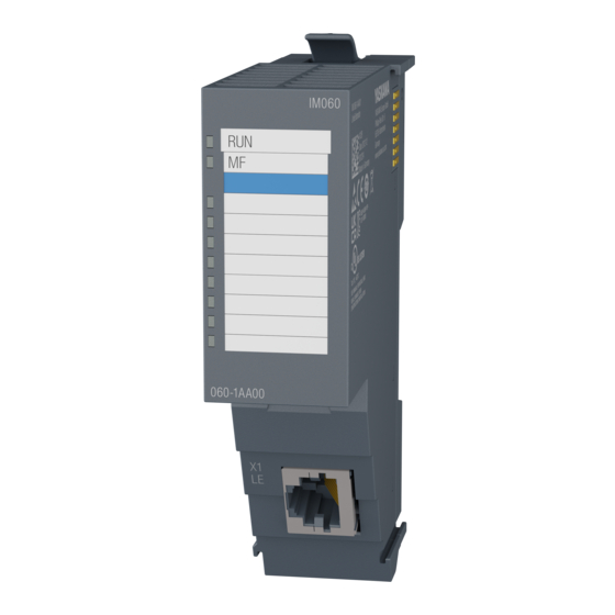
Deployment System SLIO Structure > Line extension master Structure 3.2.1 Line extension master 060-1AA0x Locking lever Labeling strip line extension LED status indication line extension Bus cover X1: Line extension 3.2.1.1 Interface X1: Line extension The connection of a line extension slave happens via this interface. 3.2.1.2 LEDs Line extension master... -
Page 39: Line Extension Slave
Deployment System SLIO Structure > Line extension slave 3.2.2 Line extension slave 061-1BA0x Locking lever terminal module Labeling strip line extension LED status indication line extension Labelling strip power module LED status indication power module Backplane bus DC 24V power section supply Power module X1: Line extension 10 Unlocking lever power module... - Page 40 The connection of a superordinate line extension master happens via this interface. CAUTION When 06x-1xA00 used - version 1: − Please use connection cables from Yaskawa for connection. The use of normal Ethernet cable can cause damage! − The connection cable must not exceed the maximum length of 2m.
- Page 41 Deployment System SLIO Structure > Line extension slave 3.2.2.2 LEDs Line extension slave PF M 061-1BA00 - version 1 Description green The line extension slave is power supplied. The power supply of the line extension slave is faulty. Line extension slave PF M Description 061-1BA01 - version 2...
-
Page 42: Mounting And Wiring
For the mounting of a line extension, there are certain rules that must be observed: CAUTION When 06x-1xA00 used - version 1: − Please use connection cables from Yaskawa for connection. The use of normal Ethernet cable can cause damage! − The connection cable must not exceed the maximum length of 2m. -
Page 43: Deployment 06X-1Xa00 - Version 1
■ Line extension slave : 061-1BA00 ■ Connection cable from Yaskawa: – 950-0KD30: RJ45, length 2m Please note that mixing master and slave between version 1 and version 2 is not permitted and will lead to malfunctions! The 06x-1xA00 is supported by the following System SLIO modules... - Page 44 Line extension master 060-1AA00 Line extension slave 061-1BA00 Connection cable from Yaskawa with a maximum length of 2m. For each line extension the max. number of pluggable modules is decreased by 1. HB300 | IM | 06x-1xA0x | en | 24-02...
-
Page 45: Deployment 06X-1Xa01 - Version 2
Line extension master : 060-1AA01 ■ Line extension slave : 061-1BA01 ■ Connection cable from Yaskawa: – 950-0KD30: RJ45, length 2m – 950-0KD40: RJ45, length 5m – 950-0KD50: RJ45, length 10m Please note that mixing master and slave between version 1 and... - Page 46 Line extension master 060-1AA01 Line extension slave 061-1BA01 Connection cable from Yaskawa with a maximum length of 10m. For each line extension the max. number of pluggable modules is decreased by 2. HB300 | IM | 06x-1xA0x | en | 24-02...
-
Page 47: Technical Data
Deployment System SLIO Technical data > 060-1AA00 Line extension master - version 1 Technical data 3.6.1 060-1AA00 Line extension master - version 1 Order no. 060-1AA00 Type IM 060 - Line extension master Module ID 8080 8080 Technical data power supply Power supply (rated value) DC 5 V Power supply (permitted range) - Page 48 Deployment System SLIO Technical data > 060-1AA00 Line extension master - version 1 Order no. 060-1AA00 Number of participants, max. Node addresses Transmission speed, min. Transmission speed, max. Address range inputs, max. Address range outputs, max. Number of TxPDOs, max. Number of RxPDOs, max.
-
Page 49: 060-1Aa01 Line Extension Master - Version 2
Deployment System SLIO Technical data > 060-1AA01 Line extension master - version 2 3.6.2 060-1AA01 Line extension master - version 2 Order no. 060-1AA01 Type IM 060 - Line extension master Module ID 8081 8080 Technical data power supply Power supply (rated value) DC 5 V Power supply (permitted range) Reverse polarity protection... - Page 50 Deployment System SLIO Technical data > 060-1AA01 Line extension master - version 2 Order no. 060-1AA01 Node addresses Transmission speed, min. Transmission speed, max. Address range inputs, max. Address range outputs, max. Number of TxPDOs, max. Number of RxPDOs, max. Housing Material PPE / PPE GF10...
- Page 51 Deployment System SLIO Technical data > 061-1BA00 Line extension slave - version 1 3.6.3 061-1BA00 Line extension slave - version 1 Order no. 061-1BA00 Type IM 061 - Line extension slave Module ID Technical data power supply Power supply (rated value) DC 24 V Power supply (permitted range) DC 20.4...28.8 V...
- Page 52 Deployment System SLIO Technical data > 061-1BA00 Line extension slave - version 1 Order no. 061-1BA00 Node addresses Transmission speed, min. Transmission speed, max. Address range inputs, max. Address range outputs, max. Number of TxPDOs, max. Number of RxPDOs, max. Housing Material PPE / PPE GF10...
- Page 53 Deployment System SLIO Technical data > 061-1BA00 Line extension slave - version 2 3.6.4 061-1BA00 Line extension slave - version 2 Order no. 061-1BA01 Type IM 061 - Line extension slave Module ID 8082 8080 Technical data power supply Power supply (rated value) DC 24 V Power supply (permitted range) DC 20.4...28.8 V...
- Page 54 Deployment System SLIO Technical data > 061-1BA00 Line extension slave - version 2 Order no. 061-1BA01 Node addresses Transmission speed, min. Transmission speed, max. Address range inputs, max. Address range outputs, max. Number of TxPDOs, max. Number of RxPDOs, max. Housing Material PPE / PPE GF10...
Need help?
Do you have a question about the SLIO IM 060 and is the answer not in the manual?
Questions and answers