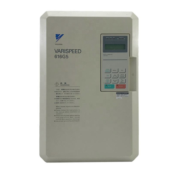
YASKAWA VARISPEED-616G5 Instructions Manual
Digital reference card
Hide thumbs
Also See for VARISPEED-616G5:
- Instructions manual (12 pages) ,
- Instruction manual (356 pages) ,
- Instructions manual (9 pages)
Subscribe to Our Youtube Channel
Summary of Contents for YASKAWA VARISPEED-616G5
- Page 1 YASKAWA VARISPEED-616G5 OPTION CARD DIGITAL REFERENCE CARD DI-16H2 INSTRUCTIONS Upon receipt of the product and prior to initial operation, read these instructions thoroughly, and retain for future reference. YASKAWA MANUAL NO. TOE-C736-40.7B...
-
Page 2: Notes For Safe Operation
NOTES FOR SAFE OPERATION Read this instruction manual thoroughly before installation, operation, maintenance or inspection. In this manual, the NOTES FOR SAFE OPERATION is classified as “CAUTION”. CAUTION Indicates a potentially hazardous situation which, if not avoided, may result in minor or moderate injury to personnel and damage to equipment. - Page 3 The digital reference card, DI−16H2 is mounted on the control board of the in- verter to set up digital speed references. To set up references using DI−16H2, set the b1−01 operation mode selection constant to 3 (option). For the values of oth- er constants, refer to ‘descriptive manual for constants’...
-
Page 4: Inspection After Delivery
S Check the name written on the product to verify that ordered products have been delivered. S Check for damage caused during transportation. If there is anything uncertain on the structure, contact your YASKAWA repre- sentative. -
Page 5: Installation Procedure
Installing to Inverter (See Fig. 2) Installation Procedure Turn OFF the main power and wait for the time specified on the cover of the inverter. Remove the cover and verify that the CHARGE indicator lamp is OFF. Plug the 2CN connector of the digital reference card DI-16H2 into the 2CN connector (60 pins) on the control board of the inverter. - Page 6 Interconnection Fig. 3 shows interconnection between the inverter, DI-16H2, and peripheral equipment. Inverter Transistor Motor L1(R) U(T1) (open collector) L2(S) V(T2) or switch L3(T) W(T3) Photocoupler Grounding lead wire Note: Connect the grounding lead wire with the control terminal on the control board of the inverter.
- Page 7 NOTE Notes on wiring S Separate the control signal wires ( from terminals TC1, TC2, and TC3 ) of the DI-16H2 from the main circuit wires and other power cables. S Use a shielded wire to connect to TC1 and TC2. Connect the wire as shown in Fig.
- Page 8 Wiring See Table 1 for the functions of the input terminals. The functions can be se- lected by combination of constant F3−01 setting (frequency reference setting selection) and switch S1 (reference input 12−bit/16−bit selection). Digital reference input terminal functions Table Input signal type * With SIGN Without SIGN...
- Page 9 Digital reference data [Terminal TC1-1 to -10, TC2-1 to -6 and SIGN signal (Terminal TC2-7)] SET (read) signal (Terminal TC-8) 5 ms or more 5 ms or more 10 ms or more Timing of digital reference read signal Fig. Make sure the followings when wiring. S To prevent noise, use shielded wire and separate from heavy current circuits (200VAC or greater) or relay drive circuits.
- Page 10 Notes on Use of Input Signals The input circuit of DI−16H2 receives outputs from relay contacts or (open col- lector) transistors. Note the points below: S When using relay contacts for digital instruction signals, select highly reliable relay contacts (for weak current) of a contact capacity of 30VDC or greater and 100mA or lower.
- Page 11 2 Digital reference selection Table Monitor (U1−01) Switch Constant setting Reference setting display unit Reference input mode Reference input mode range* range* selection o1−03 F3−01 o1−03=0 o1−03=1 12 bits With SIGN BCD 3 digits, 1% −110 to +110% −110 to +110% 16 bits With SIGN BCD 4 digits, 1% 12 bits...


Need help?
Do you have a question about the VARISPEED-616G5 and is the answer not in the manual?
Questions and answers