Table of Contents
Advertisement
Quick Links
Advertisement
Table of Contents
Troubleshooting

Related Manuals for Nortel Media Gateway 3200


Summary of Contents for Nortel Media Gateway 3200
- Page 1 Media Gateway 3200 H.248 User’s Manual Version SN09 Document # LTRT-72704 Rev 007...
-
Page 3: Table Of Contents
MG 3200 H.248 User's Manual Contents Contents Introductory Matter....................15 Overview of the MG 3200..................17 General Features ....................18 TP-1610 Software Overview .................. 19 1.2.1 Call Control Protocols ....................19 1.2.2 Management Protocols....................19 MG 3200 Applications ....................20 1.3.1 Available Configurations ..................20 Benefits ........................20 Functional Block Diagram ..................21 Typical Application Diagram...................22 Hardware Equipment ..................23... - Page 4 MG 3200 Restoring Networking Parameters to their Initial State .......... 49 MG 3200 Initialization & Configuration Files...........51 Boot Firmware & Operational Firmware..............51 MG 3200 Startup....................51 Using BootP/DHCP ....................53 6.3.1 BootP/DHCP Server Parameters ................53 6.3.2 Host Name Support ....................56 6.3.3 Selective BootP .......................56 6.3.4...
- Page 5 MG 3200 H.248 User's Manual Contents 8.3.5 Using Internet Explorer to Access the Embedded Web Server......145 Getting Acquainted with the Web Interface............146 8.4.1 About the Web Interface Screen ................146 8.4.2 Saving Changes ....................147 8.4.3 Protocol Management................... 149 8.4.4 Advanced Configuration Screen................
- Page 6 MG 3200 12.1.8 H.248-Specific Parameters................... 272 12.1.9 Web Interface Parameters..................276 12.1.10 SCTP Parameters....................278 13 Appendix - Table Parameters.................281 13.1 ini File Table-Parameters ..................281 14 Appendix - RTP/RTCP Payload Types............299 14.1 Payload Types Defined in RFC 3551..............299 14.2 Payload Types .....................
- Page 7 MG 3200 H.248 User's Manual Contents 17.2 SSL/TLS.......................322 17.2.1 Web Server Configuration ..................323 17.2.2 Using the Secure Web Server ................323 17.2.3 Secure Telnet ....................... 323 17.2.4 Server Certificate Replacement................324 17.2.5 Client Certificates....................325 17.3 RADIUS Support ....................326 17.3.1 Setting Up a RADIUS Server................
- Page 8 MG 3200 20.2 PSTN Trace Utilities.....................363 20.3 Enabling PSTN Trace via the Web ..............364 20.4 MEGACO Tester Utility ..................365 21 Appendix - H.248 Compliance................367 21.1 H.248 Compliance Matrix..................367 22 Appendix - SNMP Traps..................381 22.1 Alarm Traps......................381 22.1.1 Component: Board#<n> ..................381 22.1.2 Component: AlarmManager#0 ................
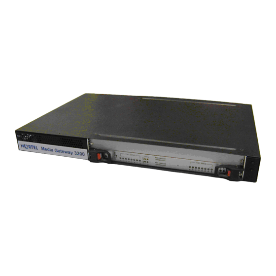
- Page 9 MG 3200 H.248 User's Manual Contents List of Figures Figure 1-1:1610 Functional Block Diagram ....................21 Figure 1-2: Typical MG 3200 Wireline Application .................22 Figure 2-1: MG 3200 Front View ......................23 Figure 2-2: 1610 Board...........................24 Figure 2-3: 1610 RTM - with Telco Connectors ..................25 Figure 2-4: 1610 Board, Panel View ......................26 Figure 2-5: 1610 RTM Panel with 2 Telco Connectors ................27 Figure 2-6: RTM Panel with 8 RJ-48c Trunk Connectors ..............28...
- Page 10 MG 3200 Figure 8-34: Change Password Screen - For Users with Administrator Privileges......181 Figure 8-35: Change Password Screen - For Users with Monitoring Privileges ......... 181 Figure 8-36: Status and Diagnostic Menu Screen ................182 Figure 8-37: Trunk and Channel Status Screen.................. 183 Figure 8-38: Channel Status Screen ....................
- Page 11 MG 3200 H.248 User's Manual Contents Figure 23-1: Customized Web Interface Title Bar ................397 Figure 23-2: Logo Image Download Screen..................398 Figure 23-3: Default Web Browser Title Bar..................402 Figure 23-4: ini Parameters Screen ....................403 Version SN09 October 2006...
- Page 12 MG 3200 List of Tables Table 2-1:Chassis Indicators ........................24 Table 2-2: Board Status LED Indicators....................29 Table 2-3: Trunk Status LED Indicators ....................29 Table 2-4: Ethernet LED Indicators ......................29 Table 2-5: Auxiliary LED Indicators ......................30 Table 3-1: MG 3200 Front View Component Descriptions..............33 Table 3-2: Connections on Each 50-Pin Telco Connector ..............38 Table 3-3: MG 3200 Rear Panel Cabling (16 Trunks, Dual AC Power) Component Descriptions ..40 Table 3-4: MG 3200 Rear Panel Cabling (8 Trunks, DC Power) Component Descriptions ....41...
- Page 13 MG 3200 H.248 User's Manual Contents Table 12-2: PSTN Parameters ......................238 Table 12-3: Infrastructure Parameters ....................246 Table 12-4: Media Processing Parameters ..................255 Table 12-5: SS7 Parameters....................... 265 Table 12-6: Common Control Parameters ..................266 Table 12-7: SNMP Parameters ......................271 Table 12-8: H.248 Specific Parameters ....................
- Page 14 MG 3200 Reader’s Notes User’s Manual Document # LTRT-72704...
-
Page 15: Introductory Matter
Information contained in this document is believed to be accurate and reliable at the time of printing. However, due to ongoing product improvements and revisions, Nortel cannot guarantee the accuracy of printed material after the Date Published nor can it accept responsibility for errors or omissions. - Page 16 All other products or trademarks are property of their respective owners. Customer Support Customer technical support and service are provided by Nortel’s Distributors, Partners, and Resellers from whom the product was purchased. For Customer support for products purchased directly from Nortel, contact mailto:support@nortel.com.
-
Page 17: Overview Of The Mg 3200
H.248 User’s Manual 1. Overview of the MG 3200 Overview of the MG 3200 The MG 3200 is the cost-effective, entry-level, market-ready, standards-compliant media server systems. Intelligently packaged in a 1U chassis, especially designed for small-scale deployments and smaller locations in the packet network, the MG 3200 is the correct solution size for small-scale needs. -
Page 18: General Features
G.729A and G.723 should not be used simultaneously on the same board. Note 2: G.728 coder can be supported. For additional information, contact your Nortel representative. Up to 16 E1/T1 digital spans Independent vocoder selection per channel Extensive media processing functions RTP stream multiple destination connection (i.e. -
Page 19: Tp-1610 Software Overview
H.248 User’s Manual 1. Overview of the MG 3200 DTMF Relay according RFC 2833 PSTN Signaling: CAS, ISDN PRI Transport of SS7 signaling, with the use of SigTran; MTP-3 and higher layer messages are relayed using M2UA via SCTP over IP MFC-R2 and Call Progress Tone detection and generation PICMG 2.1 for Hot-swap support cPSB (PICMG 2.16) support... -
Page 20: Mg 3200 Applications
Concurrent toll quality voice and fax support Wide range of PSTN signaling protocols Fast time-to-market Flexible and easy migration to VoIP networks Extensive VoIP experience accumulated by Nortel All-in-one integrated board - Reduced inventory Scalable distributed architectures Shorter development cycle User’s Manual... -
Page 21: Functional Block Diagram
H.248 User’s Manual 1. Overview of the MG 3200 Functional Block Diagram The figure below illustrates the functionality of the TP-1610 board. Figure 1-1:1610 Functional Block Diagram MPC8260 Highway AC486 Parallel SDRAM AC486 PSTN E1/T1 Trunk AC486 Interfaces AC486 AC486 AC486 Framers Flash... -
Page 22: Typical Application Diagram
MG 3200 Typical Application Diagram The diagram below illustrates a typical wireline application. Figure 1-2: Typical MG 3200 Wireline Application User’s Manual Document # LTRT-72704... -
Page 23: Hardware Equipment
H.248 User’s Manual 2. Hardware Equipment Hardware Equipment This section provides details about the hardware equipment for the MG 3200. This section also describes the MG 3200’s hardware features and details the various LED functions. The MG 3200 includes: 1U 19 inch chassis 1 TP-1610 board 1 TP-1610 Rear Transition Module (RTM) The MG 3200 Chassis... -
Page 24: Chassis Led Indicators
TP-1610 RTM panel options for up to eight RJ-48c connectors, shown in the section,' 'TP-1610 RTM Panel Diagrams'' on page 28. Consult an Nortel representative for more information on the available configurations. The figure below displays the TP-1610 board. Figure 2-2: 1610 Board User’s Manual... -
Page 25: Board Hot-Swap Support
H.248 User’s Manual 2. Hardware Equipment The figure below illustrates the TP-1610 board’s corresponding Rear Transition Module (RTM) with 50-Pin Telco Connectors. Figure 2-3: 1610 RTM - with Telco Connectors 2.2.1 Board Hot-Swap Support The TP-1610 board is hot swappable and can therefore be removed from a slot (and inserted into a slot) when the cPCI system is under power. -
Page 26: Figure 2-4: 1610 Board, Panel View
MG 3200 Figure 2-4: 1610 Board, Panel View User’s Manual Document # LTRT-72704... -
Page 27: Figure 2-5: 1610 Rtm Panel With 2 Telco Connectors
H.248 User’s Manual 2. Hardware Equipment Figure 2-5: 1610 RTM Panel with 2 Telco Connectors Version SN09 October 2006... -
Page 28: Figure 2-6: Rtm Panel With 8 Rj-48C Trunk Connectors
MG 3200 Figure 2-6: RTM Panel with 8 RJ-48c Trunk Connectors User’s Manual Document # LTRT-72704... -
Page 29: Tp-1610 Board Panel Led Indicators
H.248 User’s Manual 2. Hardware Equipment TP-1610 Board Panel LED Indicators The tables below provide the LED indicator definitions Table 2-2: Board Status LED Indicators Label Color Function FAIL Normally OFF; Red indicates board failure (fatal error) Green Board initialization sequence Bi-color terminated OK indicator... -
Page 30: Table 2-5: Auxiliary Led Indicators
MG 3200 Table 2-5: Auxiliary LED Indicators Label Color Function Green Power is supplied to the board SWAP READY The cPCI board can now be removed. Refer to Note 1. Blue The cPCI board was inserted successfully. Refer to Note 2. Note 1: Before removing the board, wait for the blue LED to flash ON and then stay OFF. -
Page 31: Hardware Installation
Open the carton and remove the packing materials. Remove the MG 3200 from the carton. Check that there is no equipment damage. Check, retain and process any documents. Notify Nortel of any damage or discrepancies. Retain any diskettes or CDs. Version SN09 October 2006... -
Page 32: Package Contents
MG 3200 3.1.1 Package Contents Ensure that the MG 3200 package includes the following items (in addition to the device): For the dual AC power supply version of the MG 3200, two AC power cables are supplied. For the DC power supply version, one connectorized DC power cable (crimp connection type) and one DC adaptor (screw connection type) connected to the rear panel of the MG 3200, - use only one type. -
Page 33: Mounting A Mg 3200 In A 19-Inch Rack
H.248 User’s Manual 3. Hardware Installation Figure 3-2: MG 3200 Front Panel Table 3-1: MG 3200 Front View Component Descriptions Item # Label Component Description FAULT Dual AC Power LED cPCI board locking screws cPCI latches TP-1610 cPCI board, 16-trunk configuration Status LED Indicators T1/E1 STATUS E1/T1 Trunk Status LED Indicators... - Page 34 MG 3200 Rack Mount Safety Instructions (UL) Note: When mounting the chassis on a rack, be sure to implement the following Safety instructions: Elevated Operating Ambient - If installed in a closed or multi-unit rack assembly, the operating ambient temperature of the rack environment may be greater than room ambient.
-
Page 35: Installing The Mg 3200 On A Desktop
H.248 User’s Manual 3. Hardware Installation Note 1: Users assembling the rear brackets by themselves should note the following: Note 2: The distance between the two rear screws is 26.5 mm. Note 3: To attach the rear brackets use 4-40 UMC screws. To place the device on a 19-inch rack's shelf take these 2 steps: Place the device on the shelf. -
Page 36: Figure 3-3: Dc Power Connector - Screw Type
MG 3200 3.2.3.3 Connecting the DC Power Supply To connect the MG 3200 to a DC power supply use one of these two options: DC Terminal block with a screw connection type. DC Terminal block with a crimp connection type. To cable the DC Power Supply with DC Terminal block with a screw connection type, take these 3 Steps: Create a DC cable by inserting two 14-16 AWG wires into the supplied adaptor (refer... -
Page 37: Connecting The E1/T1 Trunk Interfaces
H.248 User’s Manual 3. Hardware Installation Insert the terminal block to the DC inlet located on the rear of the device. Figure 3-4: DC Power Connector - Crimp Type 2 screws for connecting the crimp terminal block to the device’s rear panel 3.2.4 Connecting the E1/T1 Trunk Interfaces 3.2.4.1... -
Page 38: Figure 3-6: Rj-48C Trunk Connectors
MG 3200 Table 3-2: Connections on Each 50-Pin Telco Connector E1/T1 Number Tx Pins (Tip/Ring) Rx Pins (Tip/Ring) 1 to 8 9 to 16 27/2 26/1 29/4 28/3 31/6 30/5 33/8 32/7 35/10 34/9 37/12 36/11 39/14 38/13 41/16 40/15 If you are using RJ-48c connectors: •... -
Page 39: Figure 3-7: Rj-45 Lan Connectors And Pinout
H.248 User’s Manual 3. Hardware Installation The RJ-45 connectors labeled Ethernet 1 and Ethernet 2 are wired according to the figure below. Figure 3-7: RJ-45 LAN Connectors and Pinout 1 2 3 4 5 6 7 8 1 - Tx+ 4, 5, 7, 8 2 - Tx- 3 - Rx+... -
Page 40: Figure 3-8: Rear View With Connected Cables (16 Spans And Dual Ac)
MG 3200 3.2.4.2 MG 3200 Rear Views with Connected Cables The figures below display the MG 3200 rear view with connected cables. Figure 3-8: Rear View with Connected Cables (16 Spans and Dual AC) Table 3-3: MG 3200 Rear Panel Cabling (16 Trunks, Dual AC Power) Component Descriptions Item # Label Component Description... -
Page 41: Figure 3-9: Rear View With Connected Cables (8 Spans And Dc)
H.248 User’s Manual 3. Hardware Installation Figure 3-9: Rear View with Connected Cables (8 Spans and DC) Table 3-4: MG 3200 Rear Panel Cabling (8 Trunks, DC Power) Component Descriptions Item # Label Component Description RTM latches A Category 5 network cable, connected to the Ethernet 1 RJ-45 port PSTN 8 RJ-48c ports, each supporting a trunk... -
Page 42: Board Replacement
MG 3200 Board Replacement 3.3.1 Preliminaries Observe the general safety precautions against personal injury and equipment damage outlined in the regional Installation Safety Manual at all times. Note: Electronic components on printed circuit boards are extremely sensitive to static electricity. Normal amounts of static electricity generated by clothing can damage electronic equipment. - Page 43 H.248 User’s Manual 3. Hardware Installation 3.3.2.1 Inserting Boards Note: Make a note of the MAC address of the replacement board as it is needed for setting the correct parameter configuration for the replacement board in the element management system you are utilizing. To insert the TP-1610 board into the chassis, take these 6 steps: Hold the board horizontally.
- Page 44 MG 3200 Reader’s Notes User’s Manual Document # LTRT-72704...
-
Page 45: Software Package
H.248 User’s Manual 4. Software Package Software Package After installing the device and powering it up, you are ready to install the utilities that are included in the software package. This software package must be installed on the host PC/machine to be used to manage the device. The software package is supplied to customers on a CD accompanying the MG 3200. - Page 46 MG 3200 Reader’s Notes User’s Manual Document # LTRT-72704...
-
Page 47: Getting Started
H.248 User’s Manual 5. Getting Started Getting Started The MG 3200 is supplied with application software already resident in its flash memory (with factory default parameters). The MG 3200 is also supplied with an Embedded (integrally stored) Web Server. 'Assigning the MG 3200 IP Address' below describes how to assign an IP address to the MG 3200. -
Page 48: Assigning An Ip Address Using Bootp
MG 3200 Access the MG 3200 Embedded Web Server (refer to ''Embedded Web Server'' on page 141). In the ‘Quick Setup’ screen (shown in the ''Quick Setup Procedure'' on page 147, on page 147), set the MG 3200 ‘IP Address’, ‘Subnet Mask’ and ‘Default Gateway IP Address’... -
Page 49: Restoring Networking Parameters To Their Initial State
H.248 User’s Manual 5. Getting Started Restoring Networking Parameters to their Initial State You can use the Reset button to restore the TP-1610 networking parameters to their factory default values (described in the "Default Networking Parameters" above) and to reset the username and password. Note that this process also restores the TP-1610 parameters to their factory settings, therefore you must load your previously backed-up ini file, or the default ini file (received with the software kit) to set them to their correct values. - Page 50 MG 3200 Reader’s Notes User’s Manual Document # LTRT-72704...
-
Page 51: Mg 3200 Initialization & Configuration Files
H.248 User’s Manual 6. MG 3200 Initialization & Configuration Files MG 3200 Initialization & Configuration Files This section describes the configuration options and Initialization procedures for the MG 3200. It includes: Boot Firmware & Operational Firmware (refer to ''Boot Firmware & Operational Firmware'' on page 51) Startup Process (refer to ''MG 3200 Startup'' on page 51) BootP/DHCP (refer to ''Using BootP/DHCP' on page 53') -
Page 52: Figure 6-1: Startup Process Diagram
MG 3200 Figure 6-1: Startup Process Diagram Reset board via Power Reset Reset command from Web or board exception Interface or SNMP DHCP BootP x times x times Update network parameters from BootP/DHCP reply BootP/DHCP reply contains firmware file name? Download firmware via TFTP... -
Page 53: Using Bootp/Dhcp
H.248 User’s Manual 6. MG 3200 Initialization & Configuration Files Note 1: The BootP/DHCP server should be defined with an ini file name when you need to modify configuration parameters or when you're working with a large Voice Prompt file that is not stored in non-volatile memory and must be loaded after every reset. -
Page 54: Table 6-1: Command Line Switch Descriptions
MG 3200 TFTP server IP address - This optional parameter contains the address of the TFTP server from which the firmware file and ini file are loaded. DNS Server IP Address (Primary and Secondary) - These optional parameters contain the IP addresses of the DNS servers. These parameters are available only in DHCP and from Boot version 1.92. - Page 55 H.248 User’s Manual 6. MG 3200 Initialization & Configuration Files Table 6-1: Command Line Switch Descriptions Switch Description BootP retries: 1 = 1 BootP retry, 1 sec 2 = 2 BootP retries, 3 sec 3 = 3 BootP retries, 6 sec 4 = 10 BootP retries, 30 sec 5 = 20 BootP retries, 60 sec 6 = 40 BootP retries, 120 sec...
-
Page 56: Host Name Support
MG 3200 6.3.2 Host Name Support From Boot software version 1.92, the MG 3200 registers a device-specific Host Name on the DNS server by defining the Host Name field of the DHCP request. The host name is set to acl_nnnnnnn, where nnnnnnn is the serial number of the MG 3200 (the serial number is equal to the last 6 digits of the MAC address converted from Hex to decimal). -
Page 57: Microsoft™ Dhcp/Bootp Server
H.248 User’s Manual 6. MG 3200 Initialization & Configuration Files Table 6-2: Vendor Specific Information Field Tag # Description Value Length In door - Out door (In door is valid for FXS only. FXO is always Out door.) E&M Analog Channels The structure of the Vendor Specific Information field is demonstrated in the table below. -
Page 58: Configuration Parameters And Files
Call Progress Tones file. Up to 8 different CAS files containing specific CAS protocol definitions. These files are provided by Nortel to support various types of CAS signaling. These files are needed for CAS protocols only VXML VXML files are auxiliary files that define service logic. -
Page 59: Initialization (Ini) File
H.248 User’s Manual 6. MG 3200 Initialization & Configuration Files These files contain factory-pre-configured parameter defaults when supplied with the MG 3200 and are stored in the MG 3200's non-volatile memory. The MG 3200 is started up initially with this default configuration. Subsequently, these files can be modified and reloaded using any of the following methods: via BootP/TFTP during the startup process (refer to ''Using BootP/DHCP' on page 53'... - Page 60 MG 3200 6.4.1.1 Parameter Value Construct The following are the rules in the ini File Structure for individual ini file parameters (Parameter = Value): Lines beginning with a semi-colon ';' (as the first character) are ignored. An Enter must be the final character of each line. The number of spaces before and after "="...
-
Page 61: Table 6-5: Table Of Parameter Values Example - Remote Management Connections
H.248 User’s Manual 6. MG 3200 Initialization & Configuration Files Note: Before loading an ini file to the MG 3200, make sure that the extension of the ini file saved on your PC is correct: Verify that the checkbox Hide extension for known file types (My Computer>Tools>Folder Options>View) is unchecked. -
Page 62: Table 6-6: Table Of Parameter Values Example - Port-To-Port Connections
MG 3200 Table 6-6: Table of Parameter Values Example - Port-to-Port Connections Index Fields: 1. Source Ports 2. Destination IP 3. Destination Port Application Type Source Port Destination IP Destination Connection Name Port 2020 10.4.1.50 2020 ATM_TEST_EQ LAB_EQ 2314 212.199.201.20 4050 ATM_ITROP_LOOP LAB_EQ... - Page 63 H.248 User’s Manual 6. MG 3200 Initialization & Configuration Files 6.4.1.3 Rules in the ini File Structure for the Tables of Parameter Value Construct The ini file allows you to add/modify parameters in tables. When using tables, Read-Only parameters are not uploaded, since the Read-Only parameters cause an error when trying to download the uploaded file.
- Page 64 MG 3200 ; Table: Items Table. ; Fields: Item_Name, Item_Serial_Number, Item_Color, Item_weight. ; NOTE: Item_Color is not specified. It will be given default value. [Items_Table] ; Fields declaration Format Item_Index = Item_Name, Item_Serial_Number, Item_weight; Items_Table 0 = Computer, 678678, 6; Items_Table 6 = Computer-screen, 127979, 9;...
- Page 65 H.248 User’s Manual 6. MG 3200 Initialization & Configuration Files 6.4.1.3.2 Dynamic Tables versus Static Tables Static Table The Static table type does not support adding new lines or removing (deleting) an existing line. All lines in a Static table are pre-configured with default values. Users may modify values in existing lines.
- Page 66 MG 3200 6.4.1.3.5 Table of Parameter Value Constraints The ini file allows you to add/modify parameters in tables. When using tables, Read-Only parameters are not uploaded, since the Read-Only parameters cause an error when trying to download the uploaded file. Therefore read-only parameters should not be included in tables in the ini file.
-
Page 67: Auxiliary Files
Voice Prompt buffer size in the board is 10 Mbyte. The Voice Prompt buffer size is also controlled by the feature key. For more information contact an Nortel representative. “CallProgressTonesFilename” - The name (and path) of the file containing the Call Progress and User-Defined Tones definition. - Page 68 Call Progress Tones together is 64. The MG 3200 sample configuration file supplied by Nortel can be used to construct your own file. The Call Progress Tones and User-Defined Tones file used by the MG 3200 is a binary file with the extension tone.dat.
- Page 69 H.248 User’s Manual 6. MG 3200 Initialization & Configuration Files [CALL PROGRESS TONE #X] - containing the Xth tone definition (starting from 0 and not exceeding the number of Call Progress Tones -1 defined in the first section) using the following keys: Tone Type - Call Progress Tone type Basic Tone Type Indices...
- Page 70 MG 3200 Third Signal On Time [10 msec] - “Signal On” period (in 10 msec units) for the third cadence ON-OFF cycle. This may be omitted if there is no third cadence. Third Signal Off Time [10 msec] - “Signal Off” period (in 10 msec units) for the third cadence ON-OFF cycle.
-
Page 71: Table 6-7: Default Call Progress Tones
H.248 User’s Manual 6. MG 3200 Initialization & Configuration Files Dial Tone Ringback Tone Busy Tone Congestion Tone Warning Tone Reorder Tone Confirmation Tone Call Waiting Tone Low Freq [Hz] - Frequency in Hertz of the lower tone component for a dual frequency tone, or the frequency of the tone for a single tone. - Page 72 MG 3200 Table 6-7: Default Call Progress Tones [NUMBER OF CALL PROGRESS TONES] Number of Call Progress Tones=9 #Dial tone Tone Type=1 [CALL PROGRESS TONE #1] Tone Form = 1 (Continuous) Low Freq [Hz]=440 High Freq [Hz]=0 Low Freq Level [-dBm]=10 (-10dBm) High Freq Level [-dBm]=0 First Signal On Time [10msec]=300 #Ringback...
- Page 73 H.248 User’s Manual 6. MG 3200 Initialization & Configuration Files Table 6-7: Default Call Progress Tones [NUMBER OF CALL PROGRESS TONES] Number of Call Progress Tones=9 #Busy Tone Type=3 [CALL PROGRESS TONE #5] Tone Form = 2 (Cadence) Low Freq [Hz]=440 High Freq [Hz]=0 Low Freq Level [-dBm]=20 (-20dBm) High Freq Level [-dBm]=0...
- Page 74 MG 3200 6.4.2.2.4 Modifying the Call Progress Tones File Customers are supplied with modifiable Call Progress Tone auxiliary source files (with ini file extension) and non-modifiable Call Progress Tone dat binary files in the software package under Tones\. Only the binary dat file can be sent to the MG 3200. In the auxiliary source file, customers can modify Call Progress Tone levels, Call Progress Tone frequencies to be detected/generated by the MG 3200, to suit customer-specific requirements.
- Page 75 H.248 User’s Manual 6. MG 3200 Initialization & Configuration Files 6.4.2.2.5 Converting a Modified CPT ini File to a dat File with the Download Conversion Utility After modifying the original CPT ini file (supplied with the MG 3200's software package), you can use the Download Conversion Utility to convert the modified file into a dat binary file.
- Page 76 MG 3200 Note: The maximum number of prerecorded tones that can be stored in one dat file is 40. 6.4.2.3.2 Downloading the PRT dat File Downloading the PRT dat file into the MG 3200 can be done using one of the following: HTTP TFTP For HTTP and TFTP download, refer to ''Software Upgrade Wizard'' on page 190.
- Page 77 H.248 User’s Manual 6. MG 3200 Initialization & Configuration Files The first field is a text representation of the internal coder name. The second field is free text, and contains the name that is to be used in the SDP. The two payload fields define the default payload for this coder.
-
Page 78: Automatic Update Facility
MG 3200 6.4.2.4.4 Default Coder Table (Tbl) ini file The following is the default file for building the Coder Table (Tbl) dat file: [Internal name] [Coder name] [Txpayload] [RxPayload] [Ptime] PCMA PCMA PCMU PCMU G726-16 G726-16 G726-24 G726-24 G726-32 G726-32 G726-40 G726-40 X-G727-16... - Page 79 # DNS is required for specifying domain names in URLs DnsPriServerIP = 10.1.1.11 # Load extra configuration ini file using HTTP INIFILEURL = 'http://webserver.corp.com/Nortel/inifile.ini' # Load call progress tones using HTTPS # Note: HTTPS is not available on MP-104, MP-108, MP-124 platforms CPTFILEURL = 'https://10.31.2.17/usa_tones.dat'...
-
Page 80: Backup Copies Of Ini And Auxiliary Files
MG 3200 Create a file named master_configuration.ini, with the following text: # Common configuration for all devices # ------------------------------------ CptFileURL = 'http://www.corp.com/call_progress.dat' # Check for updates every 60 minutes AutoUpdateFrequency = 60 # Additional configuration per device # ----------------------------------- # Each device will load a file named after its MAC address, # e.g. -
Page 81: Software Upgrade Key
Note: The Software Upgrade Key is an encrypted key. Each TPM utilizes a unique key. The Software Upgrade Key is provided by Nortel only. 6.7.2 Backing up the Current Software Upgrade Key Back up your current Software Upgrade Key before loading a new key to the MG 3200. -
Page 82: Loading The Software Upgrade Key
MG 3200 6.7.3 Loading the Software Upgrade Key After receiving the Software Upgrade Key file (do not modify its contents in any way), ensure that its first line is [LicenseKeys] and that it contains one or more lines in the following format: S/N<Serial Number of TPM>... -
Page 83: Figure 6-2: Software Upgrade Key Screen
H.248 User’s Manual 6. MG 3200 Initialization & Configuration Files Figure 6-2: Software Upgrade Key Screen Figure 6-3: Example of a Software Upgrade Key File Containing Multiple S/N Lines 6.7.3.2 Loading the Software Upgrade Key Using BootP/TFTP To load the Software Upgrade Key file using BootP/TFTP, take these 5 steps: Place the file in the same location you’ve saved the MG 3200’s cmp file. -
Page 84: Verifying That The Key Was Successfully Loaded
Open the Software Upgrade Key file and check that the S/N line of the specific MG 3200 whose key you want to update is listed in it. If it isn’t, contact Nortel. Verify that you’ve loaded the correct file and that you haven’t loaded the MG 3200’s ini file or the CPT ini file by mistake. - Page 85 H.248 User’s Manual 6. MG 3200 Initialization & Configuration Files Reader’s Notes Version SN09 October 2006...
-
Page 87: Standard Control Protocols
H.248 User’s Manual 7. Standard Control Protocols Standard Control Protocols General MG 3200 can be controlled from a Media Gateway Controller (MGC) / Call Agent using standard H.238 (MEGACO Media Gateway Control). H.248 (Media Gateway Control) Protocol 7.2.1 H.238 Overview H.238 (MEGACO Media Gateway Control) Protocol is a standards-based network control protocol (based on IETF RFC 3015 and ITU-T H.248 V1). - Page 88 MG 3200 Notify command - The Notify command is used by the MG 3200 to inform the Call Agent of events occurring on one of the Terminations. Audit commands - The AuditCapabilities and AuditValue commands are used to query the MG 3200 about Termination configuration and state. This information helps in managing and controlling the MG 3200.
- Page 89 H.248 User’s Manual 7. Standard Control Protocols 7.2.2.4 Authorization Check of Call Manager IP Addresses While the H.248 specification specifies that only one Call Manager can send commands to the gateway at a time, MG 3200 gateways handle the Authorization Check in either of these modes: No authorization check is performed.
- Page 90 MG 3200 Interrupting the execution can be one of the following: Event - Only events required by the Call Agent stop the execution, and only if they do not have the KeepActive flag. New Signals Descriptor - Stops the execution, unless the same signal is received, and it has a KeepActive flag.
- Page 91 H.248 User’s Manual 7. Standard Control Protocols 7.2.2.8 Mediation Mediation in H.248 connects two ephemeral terminations. This operation can be used by a Call Agent to connect users with different coders or to connect two types of users, such as ATM and RTP.
- Page 92 MG 3200 Using these packages, the MG 3200 converts from the MFC-R2 protocol, which is a PSTN protocol, to the H.248 protocol, thereby bridging the PSTN world with the IP world. Note: Currently only E1-MFCR2 protocol is supported, there is no R1 support or T1 support.
-
Page 93: Figure 7-1: H.248-R2 Call Start Flow Diagram
H.248 User’s Manual 7. Standard Control Protocols Blocking the Bchannel is done by using the 'casblk' package. The 'blk' and 'ublk' events are reported only if the action was done by the remote side. The reason for this is that the local side already knows its status. -
Page 94: Figure 7-2: H.248-R2 Call Disconnect Flow Diagram
MG 3200 Figure 7-2: H.248-R2 Call Disconnect Flow Diagram Terminator Disconnects MFCR2 H.248 H.248 MFCR2 Outgoing MG Incoming MG Clear back NOTIFY(OE=77{icas/cb}) Wait for Disconnect timer MODIFY(SG{icas/cb}, E=88{icas/cf}) Clear back Clear forward NOTIFY(OE=88{icas/cf}) MODIFY(SG{ibcas/cf}, E=99{icas/rlg}) Clear forward Release guard NOTIFY(OE=99{icas/rlg}) MODIFY(SG{icas/rlg}, E=99{bcas/idle}) Release guard... - Page 95 H.248 User’s Manual 7. Standard Control Protocols Configuration is performed through the ini file (the DTMFTransportType=3 parameter), or through the Web. This value is used by H.248 as the default value, but commands can override it. To enable RFC 2833 via a command, add a payload type in the media line of the SDP and define this payload type to be RF 2833 according to the following example: c= IN IP4 $ m=audio $ RTP/AVP 0 97...
-
Page 96: Table 7-1: Silence Suppression Operation
MG 3200 Table 7-1: Silence Suppression Operation CONFIG G.711 G.723 G.729 Setting ON only if: ON only if: ON only if: - a=silencesupp:on - a=silencesupp:on a=silencesupp:on - payload 13 was - remote SDP does not contain - remote SDP does not contain offered on both sides the line the line... - Page 97 H.248 User’s Manual 7. Standard Control Protocols The first three lines describe the voice stream, and can differ according to the user's requirements. Attributes to the voice ('a' lines) should be added after the first 'm' line. The 'm=image' line, however, is mandatory, and should appear in the identical format to the above.
-
Page 98: Sdp Support In H.248
MG 3200 The number of Fax pages is reported in the statistics descriptor when this descriptor is requested. The number of Fax pages can also be audited during the Fax. 7.2.3 SDP Support in H.248 H.248 supports basic SDP, as defined in RFC 2327. It also supports SDP-ATM, as defined in RFC 3108. - Page 99 H.248 User’s Manual 7. Standard Control Protocols 7.2.3.1 Selecting a Coder or Ptime Using an Under-specified Local Descriptor Before the current version, the supported under-specified fields in the SDP had been: IP address Port Payload Added from the current version, the Profile and Ptime are also supported, as in the following example: c=IN IP4 $ m=audio $ $ $...
- Page 100 MG 3200 The reply to this is: MEGACO/1 [10.4.4.46]:2944 P=10264{ C=2{ A = gwRTP/1{ c=IN IP4 10.4.4.46 a=sqn: 0 a=cdsc: 1 image udptl t38 a=cpar: a=T38FaxMaxBuffer:1024 a=cpar: a=T38FaxMaxDatagram:238 m=audio 4010 RTP/AVP 0 a=ptime:20 a=silencesupp:off - - - - }}}}} In this case, the local was requested to use both audio and image, but the remote supports only the audio.
- Page 101 H.248 User’s Manual 7. Standard Control Protocols m=audio 4020 RTP/AVP 0 a=ptime:20 a=silencesupp:off - - - - a=cdsc: 2 audio RTP/AVP 0 18 4 a=cpar: a=fmtp:18 annexb=yes a=cpar: a=rtpmap:4 G723/8000/1 a=cpar: a=fmtp:4 bitrate=6.3;annexa=yes a=cpar: a=ptime:20 a=cpar: a=silencesupp:off - - - - }}}}} In Example 2, the local was requested to use both audio and image, but the remote supports only the audio and parts of the coders.
- Page 102 MG 3200 Table 32: MEGACO Mapping Payload Numbers to Coders Default Payload Number Encoding Name Coder "X-G727-40-16" G727_40_16 "X-G727-40-24" G727_40_24 "X-G727-40-32" G727_40_32 "X-NETCODER" NetCoder_4_8 "X-NETCODER" NetCoder_5_6 "X-NETCODER" NetCoder_6_4 "X-NETCODER" NetCoder_7_2 "X-NETCODER" NetCoder_8 "X-NETCODER" NetCoder_8_8 "X-NETCODER" NetCoder_9_6 "X-CCD" Transparent "EVRC0" EVRC0 "X-EVRC-TFO"...
-
Page 103: Supported H.248 Packages
H.248 User’s Manual 7. Standard Control Protocols Table 32: MEGACO Mapping Payload Numbers to Coders Default Payload Number Encoding Name Coder “RED” Redundancy per RFC 2198 “CN” Comfort Noise Note: When using dynamic payloads, do not use the MG 3200 default payloads for RFC 2833 (96) and RFC 2198 (104). -
Page 104: Table 7-2: Generic Media Package - G
MG 3200 7.2.4.1 Generic Media Package - G Table 7-2: Generic Media Package - G Symbol Definition Type cause General failure report Event Signal completion Event Notes are for all H.248 Package tables: The signal type; the following symbols identify the type of signal: OO signal: The ON/OFF signal is turned ON until commanded by the Call Agent to turn it OFF, and vice versa. -
Page 105: Table 7-4: Tone Generator Package - Tonegen
H.248 User’s Manual 7. Standard Control Protocols 7.2.4.3 Tone Generator Package - ToneGen Table 7-4: Tone Generator Package - ToneGen Symbol Definition Type Duration Plays audio tone Signal 7.2.4.4 Tone Detection Package - ToneDet Table 7-5: Tone Detection Package - ToneDet Symbol Definition Type... -
Page 106: Table 7-6: Dtmf Generator Package - Dg
MG 3200 7.2.4.5 DTMF Generator Package - DG (Extends ToneGen) Table 7-6: DTMF Generator Package - DG Symbol Definition Type Duration DTMF 0 Signal DTMF 1 Signal DTMF 2 Signal DTMF 3 Signal DTMF 4 Signal DTMF 5 Signal DTMF 6 Signal DTMF 7 Signal... -
Page 107: Table 7-7: Dtmf Detection Package - Dd
H.248 User’s Manual 7. Standard Control Protocols 7.2.4.6 DTMF Detection Package - DD (Extends ToneDet) Table 7-7: DTMF Detection Package - DD Symbol Definition Type DigitMap Completion Event Event DTMF 0 Event DTMF 1 Event DTMF 2 Event DTMF 3 Event DTMF 4 Event... -
Page 108: Table 7-8: Call Progress Tones Generator Package - Cg
MG 3200 7.2.4.7 Call Progress Tones Generator Package - CG (Extends ToneGen) Table 7-8: Call Progress Tones Generator Package - CG Symbol Definition Type Duration Map to CPT File Dial tone Signal 180 sec Ringing tone Signal 180 sec Busy tone Signal 180 sec Congestion tone... -
Page 109: Table 7-10: Basic Continuity Package - Ct
H.248 User’s Manual 7. Standard Control Protocols 7.2.4.9 Basic Continuity Package - CT Table 7-10: Basic Continuity Package - CT Symbol Definition Type Duration Map to CPT file Detects test completion Event Initiates sending the Signal 2 sec User Defined tone Responds to continuity Signal... -
Page 110: Table 7-13: Tdm Circuit Package - Tdmc
MG 3200 7.2.4.12 TDM Circuit Package - TDMC (Extends - NT) Table 7-13: TDM Circuit Package - TDMC Symbol Definition Type Maximum Jitter Buffer size Property gain Gain control Property 7.2.4.13 Generic Announcement Package - AN Table 7-14: Generic Announcement Package Symbol Definition Type... -
Page 111: Table 7-16: Basic Service Tones Generation Package - Srvtn
H.248 User’s Manual 7. Standard Control Protocols 7.2.4.15 Basic Service Tones Generation Package - SRVTN (Extends - ToneGen) Table 7-16: Basic Service Tones Generation Package - SRVTN Symbol Definition Type Duration Map to CPT File Recall dial tone Signal 180 sec conf Confirmation tone Signal... -
Page 112: Table 7-18: Basic Cas Signal/Events
MG 3200 7.2.4.17 Basic CAS Package - BCAS Table 7-18: Basic CAS Signal/Events Symbol Definition Type Duration Map to Symbol CPT File Seizure Signal/ Event None Seizure ack Signal/ Event None Answer Signal/ Event None idle idle Signal/ Event None casf CAS failure Event... -
Page 113: Table 7-20: Cas Blocking Signal/Events
H.248 User’s Manual 7. Standard Control Protocols 7.2.4.19 CAS Blocking Package - CASBLK Table 7-20: CAS Blocking Signal/Events Map to Symbol Definition Type Duration CPT File Symbol Seizure Signal/ None Event ublk Answer Event None 7.2.4.20 International CAS compelled Package - ICASC Table 7-21: ICASC Signal/Events Table Map to Symbol... -
Page 114: Table 7-22: Mf Generator Package - Mfg
MG 3200 7.2.4.21 MF Generator Package - MFG (Extends - ToneGen) Table 7-22: MF Generator Package - MFG Symbol Definition Type Duration MF 0 Signal MF 1 Signal MF 2 Signal MF 3 Signal MF 4 Signal MF 5 Signal MF 6 Signal MF 7... -
Page 115: Table 7-23: Mf Generator Package - Mfg
H.248 User’s Manual 7. Standard Control Protocols 7.2.4.22 MF Detection Package - MFD (Extends - ToneDet) Table 7-23: MF Generator Package - MFG Symbol Definition Type MF 0 Event mf 1 MF 1 Event mf 2 MF 2 Event mf 3 MF 3 Event mf 4... -
Page 116: Table 7-25: Basic Call Progress Tones Generator With Directionality Package - Bcg
MG 3200 7.2.4.24 Basic Call Progress Tones Generator with Directionality Package - BCG (Extends ToneGen) Table 7-25: Basic Call Progress Tones Generator with Directionality Package - BCG Map to CPT Symbol Definition Type Duration File Dial tone Signal 180 sec Ringing tone Signal 180 sec... -
Page 117: Profiling
H.248 User’s Manual 7. Standard Control Protocols 7.2.4.27 Extended Digit Collection Package - XDD (Extends – DD) Table 7-28: Extended digit collection Package - XDD Symbol Definition Type Extended Digitmap Completion Event Event 7.2.4.28 Enhanced Digits Collection Package - EDD Table 7-29: Enhanced Digits Collection Package - EDD Symbol Definition... -
Page 118: Termination Naming
MG 3200 7.2.6 H.248 Termination Naming The basic entities controlled by H.248 protocol are called Terminations. Physical Terminations represent a physical entity and ephemeral Terminations represent the stream. Ephemeral Terminations exist only during a connection. From version 4.4, the terminations names are defined by a new set of pattern parameters, as described in the next section. -
Page 119: Table 7-30: H.248 Endpoint Names
H.248 User’s Manual 7. Standard Control Protocols 7.2.6.3 Backward Compatibility The connection between the old naming parameters and the new ones is done by creating the name pattern from the old name parameters. Let's assume for example that the old name parameters are: GATEWAYNAME = "gw"... - Page 120 MG 3200 Table 7-30: H.248 Endpoint Names T1/J1 - CAS E1 - PRI/CAS E1 - T1/J1 - Endpoint Name E1 - Transparent Transparent 62 T1/J1 - PRI Transparent Acgw/T0/C13 Trunk#0/TS13 Trunk#0/TS13 Trunk#0/TS13 Trunk#0/TS13 Acgw/T0/C14 Trunk#0/TS14 Trunk#0/TS14 Trunk#0/TS14 Trunk#0/TS14 Acgw/T0/C15 Trunk#0/TS15 Trunk#0/TS15 Trunk#0/TS15 Trunk#0/TS15...
- Page 121 H.248 User’s Manual 7. Standard Control Protocols Table 7-30: H.248 Endpoint Names T1/J1 - CAS E1 - PRI/CAS E1 - T1/J1 - Endpoint Name E1 - Transparent Transparent 62 T1/J1 - PRI Transparent Acgw/T1/C11 Trunk#1/TS11 Trunk#1/TS11 Trunk#1/TS11 Trunk#1/TS11 Acgw/T1/C12 Trunk#1/TS12 Trunk#1/TS12 Trunk#1/TS12 Trunk#1/TS12...
- Page 122 MG 3200 Reader’s Notes User’s Manual Document # LTRT-72704...
-
Page 123: Mg 3200 Management
H.248 User’s Manual 8. MG 3200 Management MG 3200 Management Two types of MG 3200 management are detailed in this section: SNMP-Based Client Program - Refer to "Using SNMP" below Web interface - Refer to ''Embedded Web Server'' on page Using SNMP Simple Network Management Protocol (SNMP) is a standards-based network control protocol for managing elements in a network. - Page 124 MG 3200 Get Request - Specific values can be fetched via the "get" request to determine the performance and state of the device. Typically, many different values and parameters can be determined via SNMP without the overhead associated with logging into the device, or establishing a TCP connection with the device.
-
Page 125: Carrier-Grade Alarm System
H.248 User’s Manual 8. MG 3200 Management By convention, SNMP objects are always grouped in an "Entry" directory, within an object with a "Table" suffix. (The "ifDescr" object described above resides in the "ifEntry" directory contained in the "ifTable" directory). 8.1.1.3 SNMP Extensibility Feature One of the principal components of an SNMP manager is a “MIB Compiler", which allows... -
Page 126: Cold Start Trap
MG 3200 The Alarm MIB is currently a draft standard and therefore, has no OID assigned to it. In the current software release, the MIB is rooted in the <ProcuctName> MIB subtree. In a future release, after the MIB has been ratified and an OID assigned to it, it is to be moved to the official OID. - Page 127 H.248 User’s Manual 8. MG 3200 Management Each MIB is made up of a list of single MIB objects, each relating to a separate attribute within a gauge or counter. All counters and gauges give the current time value only. •...
- Page 128 MG 3200 Notification Log MIB - This standard MIB (RFC 3014 - iso.org.dod.internet.mgmt.mib-2) is supported as part of The implementation of Carrier Grade Alarms. Alarm MIB - This is an IETF proposed MIB also supported as part of The implementation of Carrier Grade Alarms. This MIB is still not standard and therefore is under the audioCodes.acExperimental branch.
- Page 129 H.248 User’s Manual 8. MG 3200 Management Other proprietary MIBs are: AcAlarm - This is a proprietary carrier-grade alarm MIB. It is a simpler implementation of the notificationLogMIB and the IETF suggested alarmMIB (both also supported in all TP-1610 boards). The acAlarm MIB has the following groups: •...
- Page 130 MG 3200 • acBoardConfigurationError - Sent when a board's settings are illegal - the trap contains a message stating/detailing/explaining the illegality of the setting. • acBoardTemperatureAlarm - Sent when a board exceeds its temperature limits. • acBoardEvResettingBoard - Sent after a board is reset. •...
-
Page 131: Snmp Interface Details
H.248 User’s Manual 8. MG 3200 Management • acSS7LinkSetStateChangeAlarm - This alarm is raised if the operational state of the SS7 linkset becomes BUSY. The alarm is cleared when the operational state of the linkset becomes -SERVICE or OFFLINE. • acSS7RouteSetStateChangeAlarm - This alarm is raised if the operational state of the SS7 routeset becomes BUSY. - Page 132 MG 3200 8.1.5.1.2 Configuration of Community Strings via SNMP To configure read-only and read-write community strings, the EM must use the srCommunityMIB. To configure the trap community string, the EM must also use the snmpVacmMIB and the snmpTargetMIB. Note: Support for the SR-COMMUNITY-MIB is to be discontinued and it is to be replaced by the standard snmpCommunity MIB in the next applicable release.
- Page 133 H.248 User’s Manual 8. MG 3200 Management To change the trap community string, take these 2 steps: The following procedure assumes that a row already exists in the srCommunityTable for the new trap community string. The trap community string can be part of the TrapGroup, ReadGroup or ReadWriteGroup.
- Page 134 MG 3200 8.1.5.2.2 Configuration of Trusted Managers via SNMP To configure Trusted Managers, the EM must use the srCommunityMIB, the snmpTargetMIB and the TGT-ADDRESS-MASK-MIB. To add the first Trusted Manager, take these 3 steps: The following procedure assumes that there is at least one configured read-write community.
- Page 135 H.248 User’s Manual 8. MG 3200 Management To delete the final Trusted Manager, take these 2 steps: The following procedure assumes that there is at least one configured read-write community. There is currently only one Trusted Manager. The taglist for columns for all rows in the srCommunityTable are currently set to MGR.
- Page 136 MG 3200 8.1.5.4.2 Configuration via the ini File In the TP-1610 board ini file, parameters below can be set to enable or disable the sending of SNMP traps. Multiple trap destinations can be supported on the media server by setting multiple trap destinations in the ini file.
- Page 137 H.248 User’s Manual 8. MG 3200 Management The ‘trap manager host name’ is configured via SNMPTrapManagerHostName. For example: ;SNMPTrapManagerHostName = 'myMananger.corp.MyCompany.com' Note: The same information that is configurable in the ini file can also be configured via the acBoardMIB. 8.1.5.4.3 Configuration via SNMP There are two MIB interfaces for the trap managers.
-
Page 138: Dual Module Interface
MG 3200 Using the SNMPTargetMIB: To add a trap destination, take this step: Add a row to the snmpTargetAddrTable with these values: Name=trapN, TagList=AC_TRAP, Params=v2cparams, where N is an unused number between 0 and 4 All changes to the trap destination configuration take effect immediately. To delete a trap destination, take this step: Remove the appropriate row from the snmpTargetAddrTable. -
Page 139: Snmp Nat Traversal
H.248 User’s Manual 8. MG 3200 Management If the module on which the GET is performed is the second module, the values in these two are different. If, on the other hand, the module is the first module, the value in the two objects are the same. -
Page 140: Administrative State Control
MG 3200 Administrative State Control 8.2.1 Node Maintenance Node maintenance for the MG 3200 is provided via an SNMP interface. The acBoardMIB provides two parameters for graceful and forced shutdowns of the MG 3200. (Refer to the note in "Graceful Shutdown" below.) These parameters are in the acBoardMIB as acgwAdminState and acgwAdminStateLockControl. -
Page 141: Embedded Web Server
H.248 User’s Manual 8. MG 3200 Management Embedded Web Server The MG 3200 boards and modules contain an Embedded Web Server to be used for device configuration and for run-time monitoring. The Embedded Web Server enables users equipped with any standard Web-browsing application such as Microsoft™ Internet Explorer™... -
Page 142: Limiting The Embedded Web Server To Read-Only Mode
MG 3200 The default Monitoring access level Username and Password for all devices is: Username: User Password: User The Enter Network Password dialog is case-sensitive. If the Embedded Web Server is left idle for more than 5 minutes, the session is expires. Subsequently, when a screen is accessed, you are prompted again for the Username and Password. -
Page 143: Correlating Pc / Mg 3200 Ip Address & Subnet Mask
H.248 User’s Manual 8. MG 3200 Management 8.3.2.2 Disabling the Embedded Web Server You can deny access to the device's Web Server by changing the default of ini file parameter DisableWebTask. The ability to disable access to the device's Web Server via HTTP provides a high level of security in which protection against unauthorized access (such as Internet hacker attacks) is included. -
Page 144: Accessing The Embedded Web Server
MG 3200 Table 8-1: Default IP Address and Subnet Mask E1/T1 Trunks IP Address Subnet Mask Trunks 1-8 10.1.10.10 255.255.0.0 Trunks 9-16 10.1.10.11 255.255.0.0 Note 1: The two IP addresses refer to two different modules residing on the same (TP-1610) board (one IP address for the module containing Trunks 1-8 and another for the module containing Trunks 9-16). -
Page 145: Using Internet Explorer To Access The Embedded Web Server
H.248 User’s Manual 8. MG 3200 Management Figure 8-1: Enter Network Password Screen 8.3.5 Using Internet Explorer to Access the Embedded Web Server Internet Explorer's security settings may block access to the Gateway's Web browser if they're configured incorrectly. If this happens, the following message appears: Unauthorized Correct authorization is required for this area. -
Page 146: Getting Acquainted With The Web Interface
MG 3200 Getting Acquainted with the Web Interface 8.4.1 About the Web Interface Screen The figure below is an example of the General layout of the Web Interface screen. Figure 8-2: Web Interface Screen - Example The Web Interface screen contains the following parts: Title bar - contains the corporate logo, background images and product name Main menu bar - always appears to the left on every screen for quick access to the other main modules... -
Page 147: Saving Changes
H.248 User’s Manual 8. MG 3200 Management Software Update - Use the menus in this module when you want to load new software or configuration files onto the device. Save Configuration - Use this menu to save configuration changes to the non-volatile (flash) memory. -
Page 148: Figure 8-3: Quick Setup Screen
MG 3200 Figure 8-3: Quick Setup Screen In the Quick Setup screen, enter or modify appropriate information for the IP Configuration, Trunk Configuration and Control Protocol (per type). In the IP Configuration section, IP Address and Subnet Mask fields, enter the appropriate addresses, which must correspond with your network IP Address settings, or you can enable the DHCP negotiation to start after reset. -
Page 149: Protocol Management
H.248 User’s Manual 8. MG 3200 Management Note: The Trunk Configuration parameters are global, and apply to all trunks. To configure trunks individually (per trunk), refer to ''Trunk Settings'' on page For the Line Code dropdown menu, select either B8ZS (bipolar 8-zero substitution) for T1 trunks only;... -
Page 150: Figure 8-4: Protocol Management Screen
MG 3200 Figure 8-4: Protocol Management Screen 8.4.3.1 Protocol Selection To select the protocol type, take these 2 steps: From the main menu list on the left, click on the Protocol Management link. The Protocol Management screen appears. Click the radio button of the desired protocol. Note: Changing the protocol type requires a device reset. -
Page 151: Figure 8-5: Basic Configuration Screen (H.248)
H.248 User’s Manual 8. MG 3200 Management From the sub-menu bar on the top, click the Basic Configuration link. The Basic Configuration screen appears. Figure 8-5: Basic Configuration Screen (H.248) Use the appropriate tables in the Appendix, ''Individual 'ini' File Parameters'' on page as a reference when configuring/modifying the Basic Configuration parameter fields in the ‘Basic Configuration’... -
Page 152: Figure 8-6: General Parameters Screen (H.248)
MG 3200 From the sub-menu bar on the top, click the General Parameters link. The General Parameters screen appears. Figure 8-6: General Parameters Screen (H.248) Use the appropriate tables in the Appendix, ''Individual 'ini' File Parameters'' on page as a reference when configuring/modifying the General Configuration parameter fields in the General Parameters screen. -
Page 153: Figure 8-7: Channel Configuration Screen (H.248)
H.248 User’s Manual 8. MG 3200 Management 8.4.3.4 Channel Configuration To configure the Channel Configuration take these 4 steps: From the main menu list on the left, click on the Protocol Management link. The Protocol Selection screen appears. From the sub-menu bar on the top, click the Channel Configuration link. The Channel Configuration screen appears. -
Page 154: Advanced Configuration Screen
MG 3200 8.4.3.5 Advanced Configuration To configure the Advanced Configuration take these 4 steps: From the main menu list on the left, click on the Protocol Management link. The Protocol Selection screen appears. From the sub-menu bar on the top, click the Advanced Configuration link. The Advanced Configuration screen appears. -
Page 155: Figure 8-9: Network Settings Drop-Down Menu
H.248 User’s Manual 8. MG 3200 Management • Security Settings - Refer to ''Security Settings'' on page • RTP Settings - Refer to ''RTP Settings'' on page • Routing Table - Refer to ''Routing Table'' on page • Ethernet Port Information - Refer to ''Ethernet Port Information'' on page Figure 8-9: Network Settings Drop-Down Menu •... -
Page 156: Figure 8-11: Ss7 Settings Drop-Down Menu
MG 3200 • SigTran Interface IDs - Refer to 'SigTran Interface IDs Table Parameters' Figure 8-11: SS7 Settings Drop-Down Menu TDM Bus Settings - Refer to ''TDM Bus Settings'' on page Configuration File - Refer to ''Configuration File'' on page Regional Settings - Refer to ''Regional Settings'' on page Change Password - Refer to ''Change Password'' on page Figure 8-12: Advanced Configuration Parameters Screen (SS7 disabled) -
Page 157: Figure 8-13: Advanced Configuration Parameters Screen (Ss7 Enabled)
H.248 User’s Manual 8. MG 3200 Management Figure 8-13: Advanced Configuration Parameters Screen (SS7 enabled) 8.4.4.1 IP Settings To configure the IP Settings, take these 4 steps: From the main menu list on the left, click on the Advanced Configuration link. The Advanced Configuration screen appears. -
Page 158: Figure 8-15: Application Settings Screen
MG 3200 8.4.4.2 Application Settings To configure the Application Settings, take these 6 steps: From the main menu list on the left, click on the Advanced Configuration link. The Advanced Configuration screen appears. From the sub-menu bar on the top, move the cursor on the Network Settings link. A drop-down menu appears. -
Page 159: Figure 8-16: Snmp Manager's Table Screen
H.248 User’s Manual 8. MG 3200 Management To access the SNMP Managers table, click the arrow button. The SNMP Manager’s Table screen appears. Figure 8-16: SNMP Manager’s Table Screen The SNMP Managers table allows you to configure the SNMP manager's attributes. Note: By un-checking a checkbox and clicking submit, the whole table row is deleted. -
Page 160: Figure 8-17: Web & Telnet Access List Screen
MG 3200 From the sub-menu bar on the top, move the cursor on the Network Settings link. A drop-down menu appears. Click on the Web & Telnet Access List option. The Web & Telnet access List screen appears. Figure 8-17: Web & Telnet Access List Screen To add a new authorized IP address, in the New Authorized IP Address field at the bottom portion of the screen, enter the desired IP address and click the Add New Address button. -
Page 161: Figure 8-18: Security Settings Screen
H.248 User’s Manual 8. MG 3200 Management 8.4.4.4 Security Settings To configure the Security Settings, take these 15 steps: From the main menu list on the left, click on the Advanced Configuration link. The Advanced Configuration screen appears. From the sub-menu bar on the top, move the cursor on the Network Settings link. A drop-down menu appears. -
Page 162: Table 8-2: Available Access Levels And Their Privileges
Basic – Clear text is used during authentication. Digest when possible – This is the default setting. MD5 authentication is used. Basic if HTTPS, Digest if HTTP – This setting is required for Nortel IEMS Interworking. Digest is not required when using HTTPS since the channel is already encrypted. -
Page 163: Figure 8-19: Ipsec Table Screen (Existing Table Row)
H.248 User’s Manual 8. MG 3200 Management To access the IPSec table, on the IPSec Table row, click the arrow button. The IPSec Table screen appears. Figure 8-19: IPSec Table Screen (Existing Table Row) Version SN09 October 2006... -
Page 164: Figure 8-20: Ipsec Table Screen (Non -Existing Table Row)
MG 3200 Figure 8-20: IPSec Table Screen (Non -Existing Table Row) Each screen represents a single row in the Security Settings table. User can navigate between rows by selecting the desired row index in the Policy Index drop-down list at the top of the screen. -
Page 165: Figure 8-21: Ike Table Screen (Existing Table Row)
H.248 User’s Manual 8. MG 3200 Management To access the IKE table, click the arrow button. The IKE Table screen appears. Figure 8-21: IKE Table Screen (Existing Table Row) Version SN09 October 2006... -
Page 166: Figure 8-22: Ike Table Screen (Non -Existing Table Row)
MG 3200 Figure 8-22: IKE Table Screen (Non -Existing Table Row) Each screen represents a single row in the IKE table. User can navigate between rows by selecting the desired row index in the Policy Index drop-down list at the top of the screen. -
Page 167: Figure 8-23: Rtp Settings Screen (Network Settings)
H.248 User’s Manual 8. MG 3200 Management From the sub-menu bar on the top, move the cursor on the Network Settings link. A drop-down menu appears. Click ON the RTP Settings option. The RTP Settings screen appears. Figure 8-23: RTP Settings Screen (Network Settings) Use the appropriate tables in the Appendix, ''Individual 'ini' File Parameters'' on page as a reference when configuring/modifying the RTP Settings parameter fields in the RTP Settings screen. -
Page 168: Figure 8-25: Ethernet Port Information Screen
MG 3200 To add a new routing entry, in the Add a new table entry fields at the bottom portion of the screen, enter a the entry data and the click the Add New Entry button. To delete an existing entry in the upper portion of the screen, click a checkmark in the checkbox of the desired IP address row (more than one checkmark is permissible) and then click the Delete Selected Entries button. -
Page 169: Figure 8-26: Voice Settings Screen
H.248 User’s Manual 8. MG 3200 Management 8.4.4.8 Voice Settings To configure the Voice Settings, take these 4 steps: From the main menu list on the left, click on the Advanced Configuration link. The Advanced Configuration screen appears. From the sub-menu bar on the top, move the cursor on the Channel Settings link. A drop down menu appears. -
Page 170: Figure 8-27: Fax/Modem/Cid Settings Screen
MG 3200 8.4.4.9 Fax/Modem/CID Settings To configure the Fax/Modem/CID Settings, take these 4 steps: From the main menu list on the left, click on the Advanced Configuration link. The Advanced Configuration screen appears. From the sub-menu bar on the top, move the cursor on the Channel Settings link. A drop-down menu appears. -
Page 171: Figure 8-28: Rtp Settings Screen (Channel Settings)
H.248 User’s Manual 8. MG 3200 Management 8.4.4.10 RTP Settings To configure the RTP Settings, take these 4 steps: From the main menu list on the left, click on the Advanced Configuration link. The Advanced Configuration screen appears. From the sub-menu bar on the top, move the cursor on the Channel Settings link. A drop-down menu appears. -
Page 172: Figure 8-29: Ipmedia Settings Screen
MG 3200 From the sub-menu bar on the top, move the cursor on the Channel Settings link. A drop-down menu appears. Click on the IPmedia Settings option. The IPmedia Settings screen appears. Figure 8-29: IPmedia Settings Screen Use the appropriate tables in the Appendix, ''Individual 'ini' File Parameters'' on page as a reference when configuring/modifying the IPmedia Settings parameter fields in the IPmedia Settings screen. - Page 173 H.248 User’s Manual 8. MG 3200 Management 8.4.4.12 Trunk Settings To view the Trunk Settings, take these 11 steps: From the main menu list on the left, click on the Advanced Configuration link. The Advanced Configuration screen. From the Advanced Configuration screen, click the Trunk Settings option in the sub- menu bar on the top.
-
Page 174: Table 8-3: Trunk Status Color Indicator Key
MG 3200 Table 8-3: Trunk Status Color Indicator Key Indicator Color Status Description Gray Disabled Green Active - OK Yellow RAI Alarm Remote Alarm Indication (the yellow alarm) LOS/LOFS Loss of Signal or Loss of Frame – move the cursor on trunk to view the alarm type Blue AIS Alarm Alarm Indication Signal (the blue alarm) -
Page 175: Figure 8-30: Q931 Bit Map Screen
H.248 User’s Manual 8. MG 3200 Management Figure 8-30: Q931 Bit Map Screen For the Clock Master (the trunk clock source) drop-down list, select either ‘Recovered’ (the clock is recovered from the trunk; default) or ‘Generated’ (the trunk clock source is provided by the internal/TDM bus clock source) the above selection depends on the parameter ‘TDM Bus Clock Source’. -
Page 176: Figure 8-31: Tdm Bus Settings Screen
MG 3200 Note 1: A device reset may be needed in certain circumstances for the setup to be activated, if a reset is needed the Web interface alerts the user. In case such a device reset is needed, click the Reset link in main menu to the left, choose the Burn option and click the Reset button to restart the device with the new configuration.' (Refer to 'Rese't Button' on page 205.) Note 2:... - Page 177 The ini file with parameters set at their default values is on the CD accompanying the device. The ini file can also be received as an e-mail attachment from Nortel Technical Support. Users can also generate their own ini file using The DConvert utility (refer to the Appendix, ''Utilities'' on page 353).
-
Page 178: Figure 8-32: Configuration File Screen
MG 3200 To save the ini file to the PC, take these 3 steps: From the main menu list on the left, click on the Advanced Configuration link. The Advanced Configuration screen appears. From the Advanced Configuration screen, click the Configuration File link in the sub- menu bar on the top. - Page 179 The files are available on the CD accompanying your device. They can also be received as an e-mail attachment from Nortel Technical Support. A Call Progress Tones txt file can be modified and converted into the binary dat file (refer to 'Converting a CPT ini File to a Binary dat File' in the Appendix, 'Utilities').
- Page 180 Settings screen appears. (Refer to the figure below.) Click the Browse button to locate the predefined Call Progress Tone, CAS, or Voice Prompt file as appropriate. (A new software file package may be issued from Nortel or your local supplier.) Click the Send File button.
-
Page 181: Figure 8-34: Change Password Screen - For Users With Administrator Privileges
H.248 User’s Manual 8. MG 3200 Management 8.4.4.15.1 Change Password To change the Password, take these 4 steps: From the main menu list on the left, click on the Advanced Configuration link. The Advanced Configuration screen appears. From the sub-menu bar on the top, click the Change Password link. The Change Password screen appears. -
Page 182: Status And Diagnostic Menu
MG 3200 To apply new settings to the Monitoring level, click the Change Monitoring Password button. The new username/password takes effect immediately. When making a change, note that the Password and Username can be up to 7 characters and that they are case sensitive. The new password takes effect immediately. -
Page 183: Figure 8-37: Trunk And Channel Status Screen
H.248 User’s Manual 8. MG 3200 Management 8.4.5.1 Trunk and Channel Status To access the Trunk and Channel Status screen, take these 3 steps: From the main menu list on the left, click on the Status and Diagnostics link. The Status and Diagnostics screen appears. -
Page 184: Figure 8-38: Channel Status Screen
MG 3200 Table 8-4: Trunk and Channel Status Color Indicator Key Trunk Channel Indicator Color Description Indicator Color Description Gray Disabled Gray Inactive Green Active - OK Green Active Yellow RAI Alarm Purple LOS/LOF Alarm Black Non-Voice Blue AIS Alarm Orange D-Channel Alarm To display a screen with a summary of parameter information relevant to a channel,... -
Page 185: Figure 8-39: Rtp/Rtcp Settings Screen
H.248 User’s Manual 8. MG 3200 Management Figure 8-39: RTP/RTCP Settings Screen Figure 8-40: Fax & Modem Settings Screen Figure 8-41: Transport Settings Screen Version SN09 October 2006... -
Page 186: Figure 8-42: Voice Settings Screen
MG 3200 Figure 8-42: Voice Settings Screen Figure 8-43: IBS Detector Settings Screen Figure 8-44: Jitter Buffer Settings Screen Figure 8-45: IPmedia Settings Screen User’s Manual Document # LTRT-72704... - Page 187 H.248 User’s Manual 8. MG 3200 Management 8.4.5.2 Message Log The Message Log is similar to a Syslog. It provides debug messages useful in pursuing troubleshooting issues. The Message Log serves the Web Server and is similar to a Syslog server. It displays debug messages.
-
Page 188: Figure 8-46: Message Log Screen
MG 3200 To activate the Message Log, take these 4 steps: From the main menu list on the left, click on the Status and Diagnostics link. The Status and Diagnostics screen appears and Log is activated. From the sub-menu bar on the top, click the Message Log link. The Message Log screen appears. -
Page 189: Software Update
H.248 User’s Manual 8. MG 3200 Management The screen also displays any loaded files in the device. To display the Device Information screen, take these 2 steps: From the main menu list on the left, click on the Status and Diagnostics link. The Status and Diagnostics screen appears. - Page 190 MG 3200 Software Upgrade Wizard - Refer to ‘Software Upgrade Wizard’ on page 190 Load Auxiliary Files - Refer to ‘Auxiliary Files Download’ on page 199 Software Upgrade Key - Refer to ‘Software Upgrade Key’ on page 200 8.4.6.1 Software Upgrade Wizard The Software Upgrade Wizard allows the user to upgrade the MG 3200's software by loading a new *.cmp file together with the ini and a full suite of auxiliary files.
- Page 191 H.248 User’s Manual 8. MG 3200 Management Special Note for CAS file: For release prior to 5.0, it is recommended to always use a unique filename when downloading CAS files to the MG3200 gateway. For example, alter the filename by including a unique release identifier, date time string, or other meaningful text.
-
Page 192: Figure 8-48: Software Upgrade Screen
MG 3200 Figure 8-48: Software Upgrade Screen On the sub-menu bar on the top, click the Software Upgrade Wizard link. The Start Software Upgrade screen appears. (Figure 8-49) Figure 8-49: Start Software Upgrade Screen Note: At this point you may cancel the Software Upgrade process with no consequence to the device by using the cancel button. -
Page 193: Figure 8-50: Load Cmp File Screen
H.248 User’s Manual 8. MG 3200 Management Note: When in the Wizard process, the rest of the Web application is unavailable and the background Web screen is disabled. After the process is completed, access to the full Web application is restored. Figure 8-50: Load CMP File Screen Note the file type list in the left side of the screen. -
Page 194: Figure 8-51: File Loading Screen
MG 3200 Figure 8-51: File Loading Screen Figure 8-52: cmp file successfully loaded Notification Screen All four buttons (Cancel, Reset, Back, and Next) in the bottom portion of the screen are now activated. You may choose between these options: • Loading the ini file and/or additional Auxiliary Files •... -
Page 195: Figure 8-53: File Loading Screen - Ini File
H.248 User’s Manual 8. MG 3200 Management • Cancel Upgrade Process and revert to the Previous Configuration Files Loading ini file and/or additional Auxiliary Files To move to the next file type on the list to the left, click the Next button. The File Loading screen appears with the next relevant file type highlighted. -
Page 196: Figure 8-54: File Loading Screen - Cpt File
MG 3200 Figure 8-54: File Loading Screen – CPT file From any of the file type screens, you can choose to complete the Software Upgrade Process (Refer to Step 9 Completing the Software Upgrade Process) or cancel the Upgrade to revert back to the previous configuration (Refer to Step 10 Revert to the Previous Configuration Files). -
Page 197: Figure 8-55: Finish Screen
H.248 User’s Manual 8. MG 3200 Management Figure 8-55: FINISH Screen Figure 8-56: FINISH Screen - Reset Version SN09 October 2006... -
Page 198: Figure 8-57: File Burning Screen
MG 3200 During the Reset process, the device ‘burns’ the newly loaded configuration to the non-volatile memory. The File Burning screen appears displaying the File Burning to Flash Memory progress bar (Figure 8-57). When this is completed, the End Process screen appears displaying the current configuration information. - Page 199 H.248 User’s Manual 8. MG 3200 Management The software upgrade process is now completed. Note: Ensure to enable the traffic after Upgrade is complete. Refer to Appendix – Resume MG 3200 Traffic after Software Upgrade is Completed on page 409. 8.4.6.2 Auxiliary Files Download The Auxiliary Files Download screen facilitates the download of software updates using the...
-
Page 200: Figure 8-59: Auxiliary Files Download Screen
MG 3200 From the sub-menu bar on the top, click the Auxiliary Files Download link. The Auxiliary Files Download screen appears. Figure 8-59: Auxiliary Files Download Screen Use the Browse button to locate the appropriate file on your PC. Click the Send File button. The files are sent to the MG 3200. To commit the changes to the non-volatile (flash) memory, in the main menu on the left, click the Save Configuration link. - Page 201 Note: The Software Upgrade Key is an encrypted key. Each TPM utilizes a unique key. The Software Upgrade Key is provided by Nortel only. 8.4.6.3.2 Backing up the Current Software Upgrade Key Back up your current Software Upgrade Key before loading a new key to the MG 3200.
- Page 202 MG 3200 8.4.6.3.4 Loading the Software Upgrade Key Using the Embedded Web Server To load a Software Upgrade Key using the Web Server, take these 5 steps: Access the MG 3200's Embedded Web Server (refer to “Accessing the Embedded Web Server” on page 144). Click the Software Update button.
-
Page 203: Figure 8-60: Software Upgrade Key Screen
H.248 User’s Manual 8. MG 3200 Management Figure 8-60: Software Upgrade Key Screen Figure 8-61: Example of a Software Upgrade Key File Containing Multiple S/N Lines 8.4.6.3.5 Loading the Software Upgrade Key Using BootP/TFTP To load the Software Upgrade Key file using BootP/TFTP, take these 5 steps: Place the file in the same location you’ve saved the MG 3200’s cmp file. - Page 204 Open the Software Upgrade Key file and check that the S/N line of the specific MG 3200 whose key you want to update is listed in it. If it isn’t, contact Nortel. Verify that you’ve loaded the correct file and that you haven’t loaded the MG 3200’s ini file or the CPT ini file by mistake.
-
Page 205: Save Configuration
H.248 User’s Manual 8. MG 3200 Management 8.4.7 Save Configuration The Save Configuration screen allows users to save the current parameter configuration and the loaded files to the MG 3200's non-volatile (flash) memory. Note: If you perform a reset with the Burn option selected immediately after making the changes to the configuration, there is no need to use the Save Configuration function prior to the reset. -
Page 206: Reset Button
MG 3200 8.4.8 Reset Button The Reset link in the main menu on the left allows the user to initiate a device reset following which the device utilizes the new configuration stored in the non-volatile (flash) memory. To use the Reset Button screen, take these 3 steps: From the main menu list on the left, click on the Reset button. -
Page 207: Restoring And Backing Up The Device Configuration
H.248 User’s Manual 8. MG 3200 Management Restoring and Backing Up the Device Configuration The 'Configuration File' screen enables you to restore (load a new ini file to the device) or to back up (make a copy of the ini file and store it in a directory on your PC) the current configuration the device is using. -
Page 209: Diagnostics & Troubleshooting
H.248 User’s Manual 9. Diagnostics & Troubleshooting Diagnostics & Troubleshooting Syslog The Syslog server (refer to the figure below), now available with version 4.6, enables filtering of messages according to priority, IP sender address, time, date, etc. Customers can alternatively choose to download and use the following examples of the many Syslog servers available as shareware on the Internet: Kiwi Enterprises: http://www.kiwi-enterprises.com/software_downloads.htm... -
Page 210: Operating The Syslog Server
MG 3200 The Syslog message is transmitted as an ASCII message. The message starts with a leading "<" ('less-than' character), followed by a number, which is followed by a ">" ('greater-than' character). This is optionally followed by a single ASCII space. The number described above is known as the Priority and represents both the Facility and Severity as described below. -
Page 211: The Embedded Web Server's 'Message Log' (Integral Syslog)
H.248 User’s Manual 9. Diagnostics & Troubleshooting detailed information on the BootP/TFTP Server, refer to the Appendix, ''BootP/TFTP Server'' on page 223. For an ini file example showing this parameter, refer to ''Setting Syslog Server IP Address, Enabling Syslog, in an ini File'' on page and to the Example of Setting Syslog Server IP Address, Enabling Syslog, in an ini File below. - Page 212 MG 3200 CLI commands are organized in folders. When first entering the CLI, the user is located at the root folder. The CLI lists the available commands and sub folders. Enter ‘h’ at the CommandShell prompt for help on the global commands. ‘h <command name>’ will provide help on a specific command.
-
Page 213: Control Protocol Reports
H.248 User’s Manual 9. Diagnostics & Troubleshooting Control Protocol Reports 9.4.1 H.248 Error Conditions When working with H.248, the TP-1610 reports error conditions via the Call Manager (or via a Call Manager of the customer’s choice) using the standard H.248 facilities, through the network interface. -
Page 214: Solutions To Possible Problems
MG 3200 Solutions to Possible Problems 9.6.1 Possible Common Problems Solutions to possible common problems are described in the table below. Table 9-1: Solutions to Possible Common Problems Problem Possible Cause Solutions Software does not Try to “ping” the board/module. If ping fails, check for communicati function in the device network problems/definitions and try to reset the... -
Page 215: Possible Voice Problems
H.248 User’s Manual 9. Diagnostics & Troubleshooting Table 9-1: Solutions to Possible Common Problems Problem Possible Cause Solutions Wrong ini file name Verify in Windows Explorer that file extensions are displayed and the ini file is not XXX.ini.ini by mistake. Also verify that the extension ini is in lowercase letters. - Page 216 MG 3200 Reader’s Notes User’s Manual Document # LTRT-72704...
-
Page 217: Functional Specifications
H.248 User’s Manual 10. Functional Specifications Functional Specifications 10.1 MG 3200 Selected Technical Specifications The table below includes selected technical specification for both wireline application support. Table 10-1: Selected Technical Specifications Item Characteristic Channel Capacity Network Ports/DSP Calls Up to 480 (independent digital voice, fax or All media processing ports can be tied to IP-RTP, PSTN-DS0 data ports) - Page 218 MG 3200 Table 10-1: Selected Technical Specifications Item Characteristic Voice Compression G.711 PCM, 64 kbps (µ-law/A-law) (Independent dynamic vocoder G.726/G.727 ADPCM/E-ADPCM (16 to 40 kbps) selection per channel) G.723.1 MP-MLQ, 6.3 kbps ACELP, 5.3 kbps G.729A CS-ACELP, 8.0 kbps G.729 and G.723 should not be used simultaneously on the same board when using cellular coder templates Silence Suppression G.723.1 Annex A...
- Page 219 H.248 User’s Manual 10. Functional Specifications Table 10-1: Selected Technical Specifications Item Characteristic (RFC 3332) over SCTP (RFC 2960) transferring MTP-3 payload PSTN Protocols CAS - T1 robbed bit: WinkStart, delay dial, immediate start, FGB, FGD, etc. MFC-R2 numerous country variants Unique script for each county variant, enabling maximum flexibility of the entire state machine of each CAS protocol.
- Page 220 MG 3200 Table 10-1: Selected Technical Specifications Item Characteristic Physical Characteristics Enclosure Dimensions 1U, 19-inch rack mount, shelf or desk top, 2-slot cPCI chassis 44.5 x 445 x 300 mm; 1.75 x 17.5 x 12 inch (h x w x d) 2 rear mounting flanges - Optional Supply Voltages and Power 40.7 W, 3 A at 5 V, 7.8 A at 3.3 V...
- Page 221 H.248 User’s Manual 10. Functional Specifications Table 10-1: Selected Technical Specifications Item Characteristic Environmental NEBS Level 3: GR-63-Core, GR-1089-Core, Type 1&3 (approved) For DC powered version Complies with ETS 300019-1, -2, -3 (T1.1, T2.3 & T3.2) Diagnostics Front panel LEDs Provide visual status indications and alarms Syslog events Supported by Syslog servers...
- Page 222 MG 3200 Reader’s Notes User’s Manual Document # LTRT-72704...
-
Page 223: Appendix - Bootp/Tftp Server
H.248 User’s Manual 11. Appendix - BootP/TFTP Server Appendix - BootP/TFTP Server 11.1 Introduction The BootP/TFTP Server enables easy configuration and provisioning MG 3200 Media Gateways. The BootP and TFTP servers contain specific adaptations as per manufacturer requirements. The latest version of the BootP/TFTP application is 2.3.0.5. 11.1.1 Key Features Internal BootP server supporting hundreds of entities Internal TFTP server... -
Page 224: Specifications
MG 3200 11.1.2 Specifications BootP standards: RFC 951 and RFC 1542 TFTP standards: RFC 1350 and RFC 906 Operating System: Windows 98, Windows NT and Windows 2000, Windows XP Maximum number of MAC entries: 200 BootP Fields: • Hardware address (MAC): 12 hex digits •... -
Page 225: Logging Screen
H.248 User’s Manual 11. Appendix - BootP/TFTP Server 11.1.4 Logging Screen The BootP/TFTP Server main screen (refer to the figure, 'Main Screen' on page 227) includes the Log line, printed per BootP request with the following parameters: Hardware (MAC) address Status (found or not found in cache) Date and Time Assigned IP address (if found) -
Page 226: Client Configuration Screen
MG 3200 11.1.6 Client Configuration Screen The Client Configuration screen (refer to the figure, 'Client Configuration Screen' on page 229) shows: All client entities Name IP per entity With this screen, users can: Add a new entry Delete an existing entry Modify an existing entry Test a selected client for finding all BootP servers that respond to a BootP request with a specific MAC address... -
Page 227: Screen Details
H.248 User’s Manual 11. Appendix - BootP/TFTP Server 11.2 Screen Details 11.2.1 Main Screen Figure 11-1: Main Screen The figure above shows the main screen of the BootP/TFTP Server, featuring: Program State - Pauses the program. When the program is paused, no replies to BootP requests are sent. -
Page 228: Preferences Screen
MG 3200 Log Screen - Displays all BootP requests and TFTP sessions, including the time and date of the request. In addition, the response type is also displayed: • Client Not Found • Client Found • Client’s Mac Changed • Client Disabled Listed at (when using the Test Selected Clients button). -
Page 229: Client Configuration Screen
H.248 User’s Manual 11. Appendix - BootP/TFTP Server In the BootP section, the user can select ARP mode: Dynamic or Static, and reply type: Broadcast or Unicast. For a typical application, use Dynamic ARP mode and Unicast, as shown above. This option requires the user to have administrator privileges otherwise an error message appears. - Page 230 MG 3200 In the left pane of the screen is the client list. By clicking on a client in this list, the following parameters for this client are displayed on the right side of the screen: Client MAC - This is the MAC address of the client. When the user edits the MAC, a new client is added, with the same parameters as the previous client.
-
Page 231: Templates Screen
H.248 User’s Manual 11. Appendix - BootP/TFTP Server 11.2.4 Templates Screen The figure below shows the Templates screen, which provides a fast way to configure a number of clients that have the same parameters (except for the IP address). To use the Templates screen, create a template, and then apply the template to the client by selecting Figure 11-4: Templates Screen Version SN09... - Page 232 MG 3200 Reader’s Notes User’s Manual Document # LTRT-72704...
-
Page 233: Appendix - Individual Ini File Parameters
H.248 User’s Manual 12. Appendix - Individual ini File Parameters Appendix - Individual ini File Parameters 12.1 Individual ini File Parameters The individual parameters contained in the ini file are provided in the following parameter group tables: System Parameters (refer to ''System Parameters'' on page 233) Infrastructure Parameters (refer to ''Infrastructure Parameters'' on page 245) Media Processing Parameters (refer to ''Media Processing Parameters'' on page 254) PSTN Parameters (refer to ''PSTN Parameters'' on page 238) -
Page 234: System Parameters
MG 3200 12.1.1 System Parameters The table below lists and describes the system parameters contained in the ini file. Use this table as a reference when modifying ini file parameter values. Table 12-1: System Parameters ini File Field Name Description Host/Manual Valid Default Value... - Page 235 H.248 User’s Manual 12. Appendix - Individual ini File Parameters Table 12-1: System Parameters ini File Field Name Description Host/Manual Valid Default Value Range Range = tftp://server_ip/file, http://server_name/file, https://server_name/file CptFileUrl Links to a Call Progress Tones (CPT) NULL file to be downloaded from a remote Descr.
- Page 236 MG 3200 Table 12-1: System Parameters ini File Field Name Description Host/Manual Valid Default Value Range by “;” sign). NATBindingDefaultTimeout Defines the NAT binding lifetime, in seconds. STUN refreshes the binding Descr. information after this time expires. Range = 0 to 2592000 NTPServerIP This parameter is used to define the 0.0.0.0...
- Page 237 SystemOperationStateChange This parameter defines the System 0 or 1 Profile Operation state Change Profile. 0 = Disable 1 = Nortel AMS ATM Refer to the enumerator acSystemOperationStateChangeProfile enum for the possible values. Range = Integer >0 TelnetServerEnable Enables or disables the embedded 0 to 2 Telnet server.
-
Page 238: Pstn Parameters
MG 3200 12.1.2 PSTN Parameters The table below lists and describes the PSTN parameters contained in the ini file. Use this table as a reference when modifying ini file parameter values. Table 12-2: PSTN Parameters ini File Field Name Description Host/Manual Valid Default Value... - Page 239 H.248 User’s Manual 12. Appendix - Individual ini File Parameters Table 12-2: PSTN Parameters ini File Field Name Description Host/Manual Valid Default Value Range 0 = Trunk Enabled 1 = Trunk Disabled DS3ClockSource Selects the physical DS3 framing 0 to 2 method to be used in this board.
- Page 240 MG 3200 Table 12-2: PSTN Parameters ini File Field Name Description Host/Manual Valid Default Value Range CRC6 F = J1 Extended SuperFrame with CRC6 (Japan) ISDNDuplicateQ931BuffMode Activates / de-activates delivery of raw Q.931 messages. ISDNGeneralCCBehavior This is the bit-field used to determine several general ISDN behavior options.
- Page 241 H.248 User’s Manual 12. Appendix - Individual ini File Parameters Table 12-2: PSTN Parameters ini File Field Name Description Host/Manual Valid Default Value Range Applicable only when TrunkConfig.LineBuildOut.Overwrite=1. Should be used only by expert Users. LineBuildOut.XPM2 Controls the Framer's XPM2 register 0 to 255 value (line pulse shape control).
- Page 242 MG 3200 Table 12-2: PSTN Parameters ini File Field Name Description Host/Manual Valid Default Value Range library users. No CAS state machine is relevant. Users build their state machine in his application and controls it via commands of Open channel, send CAS, and event detection of CAS changes and digits events.
- Page 243 H.248 User’s Manual 12. Appendix - Individual ini File Parameters Table 12-2: PSTN Parameters ini File Field Name Description Host/Manual Valid Default Value Range users, it is the same as E1_RAW_CAS. E1_RAW_CAS = 9 E1_RAW_CAS – Not relevant for control protocols. Relevant for API library users.
- Page 244 MG 3200 Table 12-2: PSTN Parameters ini File Field Name Description Host/Manual Valid Default Value Range Note: NFAS trunk is not supported on T1_EURO_ISDN = 34 (Note: currently not supported) T1_DMS100_MERIDIAN_ISDN = 35 (Note : currently not supported) T1_NI1_ISDN = 36 (Note : currently not supported) E1_DUA = 37 E1_DUA –...
- Page 245 H.248 User’s Manual 12. Appendix - Individual ini File Parameters Table 12-2: PSTN Parameters ini File Field Name Description Host/Manual Valid Default Value Range acISDN_Q921_RAW_DATA_TRACE = acISDN_Q931_Q921_RAW_DATA_TR ACE = 8 acSS7_MTP2 = 10 acSS7_MTP2_AND_APPLI = 11 acSS7_MTP2_SL_L3_NO_MSU = 12 acSS7_AAL = 15 TrunkAdministrativeState Defines the administrative state of a 0 or 2...
-
Page 246: Infrastructure Parameters
MG 3200 12.1.3 Infrastructure Parameters The table below lists and describes the Infrastructure parameters contained in the ini file. Use this table as a reference when modifying ini file parameter values. Table 12-3: Infrastructure Parameters ini File Field Name Description Host/Manual Valid Default Value... - Page 247 H.248 User’s Manual 12. Appendix - Individual ini File Parameters Table 12-3: Infrastructure Parameters ini File Field Name Description Host/Manual Valid Default Value Range 2 = Enable (trigger by GARP) 3 = Enable (trigger by either media or GARP) EnableDiagnostics Checks the correct functionality of 0 to 2 the different hardware components...
- Page 248 MG 3200 Table 12-3: Infrastructure Parameters ini File Field Name Description Host/Manual Valid Default Value Range software or hardware malfunction. If a LAN failure is detected, the board performs a self reset (when not in PCI mode). 0 = Disable; 1 = Enable EnableMultipleIPs Enables the multiple IPs feature.
- Page 249 H.248 User’s Manual 12. Appendix - Individual ini File Parameters Table 12-3: Infrastructure Parameters ini File Field Name Description Host/Manual Valid Default Value Range provide device-related, initial startup parameters such as board type, current IP address, software version, Geographical Address, etc. This is not available in DHCP.
- Page 250 MG 3200 Table 12-3: Infrastructure Parameters ini File Field Name Description Host/Manual Valid Default Value Range Range: Legal IP LocalControlIPAddress Defines the IP address of the Control 0.0.0.0 when operating in a multiple IP Descr. mode. Range: Legal Subnet LocalControlSubnetMask Defines the Subnet Mask of the 0.0.0.0 Control when operating in a multiple...
- Page 251 H.248 User’s Manual 12. Appendix - Individual ini File Parameters Table 12-3: Infrastructure Parameters ini File Field Name Description Host/Manual Valid Default Value Range 3=μ-law PremiumServiceClassControlDI Sets the DiffServ for the Premium 0 to 56 FFSERV service class content and control traffic.
- Page 252 MG 3200 Table 12-3: Infrastructure Parameters ini File Field Name Description Host/Manual Valid Default Value Range Network_B(acTDMBusClockSource_ Network_B) 17 = ATM_A(acTDMBusClockSource_AT M_OC3) 18 = ATM_B(acTDMBusClockSource_AT M_OC3_B) TDMBusClockSource Selects the clock source on which See Descr. 1 to 14 the board synchronizes. 1 = Local oscillator 3 = MVIP 4 = PSTN Network...
- Page 253 H.248 User’s Manual 12. Appendix - Individual ini File Parameters Table 12-3: Infrastructure Parameters ini File Field Name Description Host/Manual Valid Default Value Range When using H.110/H.100 bus, this parameter also selects the trunk used as the clock source for the NetRef clock generation (in this case, the clock source must not be set to Network.
-
Page 254: Media Processing Parameters
MG 3200 Table 12-3: Infrastructure Parameters ini File Field Name Description Host/Manual Valid Default Value Range TDMBusSpeed Selects the TDM bus speed See Descr. according to the Bus Type as follows: Descr. SC = 0/2/3 H.110/H.100 = 3 MVIP = 0 Where: 0 = 2048 kbps 2 = 4096 kbps... - Page 255 H.248 User’s Manual 12. Appendix - Individual ini File Parameters Table 12-4: Media Processing Parameters ini File Field Name Description Host/Manual Valid Default Value Range AMDDetectionDirection Determines the AMD (Answer 0 or 1 Machine Detector) detection direction. 0 = Detection from the TDM side 1 = Detection from the Network side ATMG711DefaultLawSelect Determines the ATM G.711 Default...
- Page 256 MG 3200 Table 12-4: Media Processing Parameters ini File Field Name Description Host/Manual Valid Default Value Range RTP audio stream. Relay Caller ID (1): Presently the same as Mute. Mute Caller ID (2): CallerID signals detected and reported but muted from the RTP voice stream.
- Page 257 3 (RFC2833 Relay DTMF) = DTMFs are muted from the voice stream and relayed according to RFC 2833 Notes: For Nortel H.248 GW applications, the supported value for DTMFTransportType is ‘2’ (Transparent DTMF). - DTMFTransportType set to ‘Transparent DTMF’...
- Page 258 MG 3200 Table 12-4: Media Processing Parameters ini File Field Name Description Host/Manual Valid Default Value Range DTMF detected digits will be removed from the bearer path and relayed to the remote RTP device by use of RFC2833 DTMF relay. - DTMFTransportType set to ‘RFC2833 Relay DTMF’...
- Page 259 H.248 User’s Manual 12. Appendix - Individual ini File Parameters Table 12-4: Media Processing Parameters ini File Field Name Description Host/Manual Valid Default Value Range EnableSilenceCompression Enables or disables Silence 0 to 2 Suppression Mode. 0 = Disable = SILENCE_COMPRESION_DISABLE 1 = Enable = SILENCE_COMPRESION_ENABLE 2 = Enable without adaptation =...
- Page 260 MG 3200 Table 12-4: Media Processing Parameters ini File Field Name Description Host/Manual Valid Default Value Range cketInterval RTP packet rate. 0 = Default (set internally) (PACKET_INTERVAL_DEFAULT) 1 = 5 msec (PACKET_INTERVAL_5_MSEC) 2 = 10 msec (PACKET_INTERVAL_10_MSEC) 3 = 20 msec (PACKET_INTERVAL_20_MSEC) FaxModemBypassCoderType Sets the fax/modem bypass coder...
- Page 261 H.248 User’s Manual 12. Appendix - Individual ini File Parameters Table 12-4: Media Processing Parameters ini File Field Name Description Host/Manual Valid Default Value Range packets FaxTransportMode Sets the Fax over IP transport 0 to 3 method. 0 = Transparent 1 = Relay 2 = Bypass 3 = Transparent with Events...
- Page 262 MG 3200 Table 12-4: Media Processing Parameters ini File Field Name Description Host/Manual Valid Default Value Range MFSS5DetectorEnable Enables or disables detection of MF 0 or 1 SS5 line signaling. 0 = Disable; 1 = Enable MFTransportType Defines the type of MF transport. 0 to 3 0 = Erase MFs from voice transport not relayed to remote...
- Page 263 H.248 User’s Manual 12. Appendix - Individual ini File Parameters Table 12-4: Media Processing Parameters ini File Field Name Description Host/Manual Valid Default Value Range 0 = Variable Rate 1 = 1 kbps 2 = 3 kbps 3 = 7 kbps 4 = 13 kbps QCELP8Rate This parameter is used to configure...
- Page 264 MG 3200 Table 12-4: Media Processing Parameters ini File Field Name Description Host/Manual Valid Default Value Range Defined Tones signaling. 0 = Disable; 1 = Enable V22ModemTransportType Sets the V.22 modem transport 0 to 3 method. 0 = Transparent 2 = Bypass 3 = Transparent with Events V23ModemTransportType Sets the V.23 modem transport...
-
Page 265: Ss7 Parameters
H.248 User’s Manual 12. Appendix - Individual ini File Parameters Table 12-4: Media Processing Parameters ini File Field Name Description Host/Manual Valid Default Value Range Default = 0 = No Gain 12.1.5 SS7 Parameters The table below lists and describes the SS7 parameters contained in the ini file. Use this table as a reference when modifying ini file parameter values. -
Page 266: Parameters Common To All Control Protocols
MG 3200 Table 12-5: SS7 Parameters ini File Field Name Description Host/Manual Valid Default Value Range Forced retransmission). SS7_MTP2_Param_SUERM_ Defines the SS7 Signal Unit error rate 0 to 256 SU_D monitor D threshold. SS7_MTP2_Param_SUERM_T Defines the SS7 SUERM (Signal Unit 0 to 256 Error Rate Monitor) T threshold. - Page 267 H.248 User’s Manual 12. Appendix - Individual ini File Parameters Table 12-6: Common Control Parameters ini File Field Name Description Host/Manual Valid Default Value Range -1 = waits until all calls drop (infinite) Positive number = the number of seconds to wait CallAgentDomainName Defines a domain name to be used to NULL...
- Page 268 MG 3200 Table 12-6: Common Control Parameters ini File Field Name Description Host/Manual Valid Default Value Range H.248: 'line' for analog board and '/c' for trunking boards GatewayName Defines the media gateway's See Descr. identification name. Descr. H.248: Prefix of the gateway part of the termination name.
- Page 269 H.248 User’s Manual 12. Appendix - Individual ini File Parameters Table 12-6: Common Control Parameters ini File Field Name Description Host/Manual Valid Default Value Range Range: Integer > 0 Refer to the product's User's Manual or the enumerator mgTMGCPProfile for possible values. MGCPDefaultCoder This parameter can be used to set a G.711...
- Page 270 MG 3200 Table 12-6: Common Control Parameters ini File Field Name Description Host/Manual Valid Default Value Range Transaction Id Range and Transaction ID Base. RTCPInterval Defines the time interval between the 5000 0 to 65535 adjacent RTCP reports, in msec. SingleSIDPacketWithSCEG72 When using a G.729 coder connection 0 or 1...
-
Page 271: Snmp Parameters
H.248 User’s Manual 12. Appendix - Individual ini File Parameters 12.1.7 SNMP Parameters The table below lists and describes the SNMP parameters contained in the ini file. Use this table as a reference when modifying ini file parameter values. Table 12-7: SNMP Parameters ini File Field Name Description Host/Manual... -
Page 272: H.248-Specific Parameters
MG 3200 Table 12-7: SNMP Parameters ini File Field Name Description Host/Manual Valid Default Value Range manager's IP address;. when set to 0, traps are not sent to it. SNMPPort This parameter specifies the port 100 to number for SNMP requests and 3999 responses. - Page 273 H.248 User’s Manual 12. Appendix - Individual ini File Parameters Table 12-8: H.248 Specific Parameters ini File Field Name Description Host/Manual Valid Default Value Range ATM_BIT_FIELD_SIZE (For binary H.248) Defines the bit field 0 to 30 size for each ATM termination name level.
- Page 274 MG 3200 Table 12-8: H.248 Specific Parameters ini File Field Name Description Host/Manual Valid Default Value Range MEGACOCheckLegalityOfMGC This parameter controls whether 0 or 1 H.248 rejects commands from a Media Gateway Controller not in the provisioned list. 0 = Accept 1 = Reject MEGACOContextIDOffset Offset for the context ID generated by...
- Page 275 H.248 User’s Manual 12. Appendix - Individual ini File Parameters Table 12-8: H.248 Specific Parameters ini File Field Name Description Host/Manual Valid Default Value Range RTP_BIT_Field_Size (For binary H.248) Defines the bit field 0 to 30 size for each RTP termination name. RTP_Num Defines the starting number for each name's RTP termination level (level 0...
-
Page 276: Web Interface Parameters
MG 3200 12.1.9 Web Interface Parameters The table below lists and describes the Web Interface parameters contained in the ini file. Use this table as a reference when modifying ini file parameter values. Table 12-9: Web Parameters ini File Field Name Description Host/Manual Valid... - Page 277 H.248 User’s Manual 12. Appendix - Individual ini File Parameters Table 12-9: Web Parameters ini File Field Name Description Host/Manual Valid Default Value Range gateway, and its matching private key must be installed on the managing computer. Time and date must be correctly set on the gateway, for the client certificate to be verified.
-
Page 278: Sctp Parameters
MG 3200 Table 12-9: Web Parameters ini File Field Name Description Host/Manual Valid Default Value Range Web interface. Set to zeroes to allow Descr. all IP addresses. Range = Valid IP address WebLogoText Replaces the default logo image, NULL appearing in the upper left hand Descr. - Page 279 H.248 User’s Manual 12. Appendix - Individual ini File Parameters Table 12-10: SCTP Parameters ini File Field Name Description Host/Manual Valid Default Value Range empty string, SCTP (Stream Control Descr. Transmission Protocol) uses the value as the value of the FQDN (Fully Qualified Domain Name) parameter attached to the INIT chunk.
- Page 280 MG 3200 Reader’s Notes User’s Manual Document # LTRT-72704...
-
Page 281: Appendix - Table Parameters
H.248 User’s Manual 13. Appendix - Table Parameters Appendix - Table Parameters 13.1 ini File Table-Parameters The following ini file Table-Parameters are provided: SS7 ini File Table Parameters "SS7 Signaling Nodes Table Parameters" below ''SS7 Signaling Node Timers Table Parameters'' on page ''SS7 Signaling LinkSet Timers Table Parameters'' on page ''SS7 Signaling Link Table Parameters'' on page ''SS7 Signaling LinkSets Table Parameters'' on page... - Page 282 MG 3200 Table 13-1: SS7 Signaling Nodes Table Parameters ini File Field Name Default Value Valid Range Description SS7_SN_ACTION_ acPARAMSET_ACTI acPARAMSET_ACTIO Management Field for RESULT ON_RESULT_SUCC N_RESULT_SUCCEE Actions Result EEDED DED - acPARAMSET_ACTIO N_RESULT_FAILED SS7_SN_NAME "SN” String name for SN Params SS7_SN_TRACE_ 0 or 1 Trace level of signaling...
- Page 283 H.248 User’s Manual 13. Appendix - Table Parameters Table 13-1: SS7 Signaling Nodes Table Parameters ini File Field Name Default Value Valid Range Description SS7_SN_ROUTESET 0 to 255 RouteSet Congestion Size _CONGESTION_ (messages) of signaling WINSIZE node SS7_SN_TIMERS_IN Index of SNTimers tables (MTP3_SN_TIMER_S used for this signaling node ETS-1)
- Page 284 MG 3200 Table 13-2: SS7 Signaling Node Timers Table Parameters ini File Field Name Default Value Valid Range Description SS7_SNTIMERS_AC acPARAMSET_ACTI acPARAMSET_ACTIO Management Field for TION_RESULT ON_RESULT_SUCC N_RESULT_SUCCEE Actions Results EEDED DED - acPARAMSET_ACTIO N_RESULT_FAILED SS7_SNTIMERS_NA "SN_Timers” String name for SN timer- SS7_SNTIMERS_T6 1200 500 to 0xFFFFFFFF...
- Page 285 H.248 User’s Manual 13. Appendix - Table Parameters Table 13-2: SS7 Signaling Node Timers Table Parameters ini File Field Name Default Value Valid Range Description SS7_SNTIMERS_T23 180000 500 to 0xFFFFFFFF Timer at restarting SP, _ANSI started after T22, waiting to receive all traffic restart allowed messages SS7_SNTIMERS_T24...
- Page 286 MG 3200 Table 13-3: SS7 Signaling LinkSet Timers Table Parameters ini File Field Name Default Value Valid Range Description SS7_LKSETTIMERS acPARAMSET_ACTI acPARAMSET_ACTI Management Field for _ACTION_RESULT ON_RESULT_SUCC ON_RESULT_SUCC Actions Results EEDED EEDED - acPARAMSET_ACTI ON_RESULT_FAILE SS7_LKSETTIMERS "SN_Timers” String name for SN _NAME timer-set SS7_LKSETTIMERS...
- Page 287 H.248 User’s Manual 13. Appendix - Table Parameters Table 13-3: SS7 Signaling LinkSet Timers Table Parameters ini File Field Name Default Value Valid Range Description SS7_LKSETTIMERS 90000 500 to 0xFFFFFFFF Local inhibit ANSI test _T20_ANSI timer SS7_LKSETTIMERS 90000 500 to 0xFFFFFFFF Remote inhibit ANSI test _T21_ANSI timer...
- Page 288 MG 3200 Table 13-4: SS7 Signaling Link Table Parameters ini File Field Name Default Value Valid Range Description SS7_LINK_ACTION acPARAMSET_ acPARAMSET_A Management Field for Actions _RESULT ACTION_RESU CTION_RESULT_ Result LT_SUCCEEDE SUCCEEDED - acPARAMSET_A CTION_RESULT_ FAILED SS7_LINK_NAME "LINK” String name for Link Params SS7_LINK_OPERAT L3_OFFLINE L3_OFFLINE -...
- Page 289 H.248 User’s Manual 13. Appendix - Table Parameters Table 13-4: SS7 Signaling Link Table Parameters ini File Field Name Default Value Valid Range Description SS7_LINK_TRUNK_ Trunk number of signaling link NUMBER MAX_TRUNK_CA (TDM) PACITY - 1 SS7_LINK_TIMESL 0 to 31 Time-Slot number of signaling OT_NUMBER link (TDM)
- Page 290 MG 3200 Table 13-4: SS7 Signaling Link Table Parameters ini File Field Name Default Value Valid Range Description SS7_LINK_TNL_MG MTP2 Tunneling: MGC link C_LINK_NUMBER MAX_SIGNALING number (MTP2 \other side\ of _LINKS_PER_CA signaling link RD -1 SS7_LINK_TNL_ALI M3B_ALIGNME 0 to 255 MTP2 Tunneling: Alignment GNMENT_MODE NT_EMERGEN...
- Page 291 H.248 User’s Manual 13. Appendix - Table Parameters Table 13-4: SS7 Signaling Link Table Parameters ini File Field Name Default Value Valid Range Description OFFLINE acSS7LINKSET_PS_ACTION_I NSERVICE acSS7LINKSET_PS_ACTION_ ACTIVATE acSS7LINKSET_PS_ACTION_ DEACTIVATE SS7_SN_ACTION_ acPARAMSET_ acPARAMSET_A Management Field for Actions RESULT ACTION_RESU CTION_RESULT_ Result LT_SUCCEEDE...
- Page 292 MG 3200 Table 13-5: SS7 Signaling LinkSets Table Parameters ini File Field Name Default Value Valid Range Description SS7_LINKSET_ALT 0 - 255 Alternate mask for links within ERNATE_MASK signaling LinkSet SS7_LINKSET_TIM Timers Index of signaling ERS_INDEX (MTP3_LINKSET_ LinkSet TIMER_SETS-1) 13.1.1.4 SS7 Signaling LinkSet-Links Table Parameters Table 13-6: SS7 Signaling LinkSet-Links Table Parameters ini File Field Name Default Value...
- Page 293 H.248 User’s Manual 13. Appendix - Table Parameters Table 13-6: SS7 Signaling LinkSet-Links Table Parameters ini File Field Name Default Value Valid Range Description SS7_LINKSETLINK_ Physical number of signaling LINK_SLC MTP3_MAX_SLC link which is part of the LinkSet 13.1.1.5 SS7 RouteSets Table Parameters Table 13-7: SS7 RouteSets Table Parameters ini File Field Name Default Value...
- Page 294 MG 3200 Table 13-7: SS7 RouteSets Table Parameters ini File Field Name Default Value Valid Range Description 1 = L3_BUSY, 2 = L3_INSERVICE SS7_ROUTESET_A L3_OFFLINE L3_OFFLINE or Administrative state of signaling DMINISTRATIVE_S L3_INSERVICE RouteSet TATE 0 = L3_OFFLINE 2 = L3_INSERVICE SS7_ROUTESET_D Destination Point-Code of signaling RouteSet...
- Page 295 H.248 User’s Manual 13. Appendix - Table Parameters Table 13-8: SS7 RouteSet-Routes Table Parameters ini File Field Name Default Value Valid Range Description SS7_ROUTESETRO acPARAMSET_ acPARAMSET_A Management Field for Actions UTE_ACTION_RES ACTION_RESU CTION_RESULT_ Result LT_SUCCEEDE SUCCEEDED - acPARAMSET_A CTION_RESULT_ FAILED SS7_ROUTESETRO MTP3_LINKSET Number of signaling LinkSet...
- Page 296 MG 3200 Table 13-9: SigTran Interface Groups Table Parameters ini File Field Name Default Value Valid Range Description SS7_SIG_T_HB 2000 0 to 10000000 SigTran group T Heartbeat SS7_SIG_MIN_ASP 1 to 10 SigTran group minimal ASP number SS7_SIG_BEHAVIOU 0 to 0xFFFFFFFE SigTran group Behavior bit field SS7_SCTP_INSTAN 0xFFFE...
- Page 297 H.248 User’s Manual 13. Appendix - Table Parameters Table 13-10: SigTran Interface IDs Table Parameters ini File Field Name Default Value Valid Range Description SS7_SIG_IF_ID_VA 0 to 0xFFFFFFFE SigTran interface Id value field SS7_SIG_IF_ID_NA “INT_ID” SigTran interface Id string name SS7_SIG_IF_ID_O 0 to 0xFFFE SigTran interface Id owner...
- Page 298 MG 3200 Reader’s Notes User’s Manual Document # LTRT-72704...
-
Page 299: Appendix - Rtp/Rtcp Payload Types
H.248 User’s Manual 14. Appendix - RTP/RTCP Payload Types Appendix - RTP/RTCP Payload Types Latest RTP Payload Types are defined in RFC 3551. For coders that should have dynamic Payload types, proprietary default values out of the dynamic Payload type range have been defined. -
Page 300: Payload Types
MG 3200 Note: QCELP-13 default value (63) is not equal to the RFC 3551 value (12) due to backward compatible problem. 14.2 Payload Types 14.3 Payload Types Not Defined in RFC 3551 Table 14-2: Payload Types Not Defined in RFC 3551 Payload Type Description Basic Packet Rate [msec]... -
Page 301: Default Dynamic Payload Types Which Are Not Voice Coders
H.248 User’s Manual 14. Appendix - RTP/RTCP Payload Types Table 14-2: Payload Types Not Defined in RFC 3551 Payload Type Description Basic Packet Rate [msec] AMR 10.2 Kbps AMR 12.2 Kbps Vox ADPCM Linear PCM 14.4 Default Dynamic Payload Types Which are Not Voice Coders Table 14-3: Payload Types Not Defined in RFC 3551 Payload Type... -
Page 302: Default Rtp/Rtcp/T.38 Port Allocation
MG 3200 14.5 Default RTP/RTCP/T.38 Port Allocation The following table shows the default RTP/RTCP/T.38 port allocation. Table 14-4: Default RTP/RTCP/T.38 Port Allocation Channel Number RTP Port RTCP Port T.38 Port 4000 4001 4002 4010 4011 4012 4020 4021 4022 4030 4031 4032 4040... -
Page 303: Appendix - Dtmf, Fax And Modem Transport Modes
H.248 User’s Manual 15. Appendix - DTMF, Fax and Modem Transport Modes Appendix - DTMF, Fax and Modem Transport Modes 15.1 DTMF/MF Relay Settings Users can control the way DTMF/MF digits are transported to the remote Endpoint, using the DTMFTransport/MFTransport configuration parameters. The following four modes are supported: DTMF/MFTransportType= 0 (MuteDTMF/MF) In this mode, DTMF/MF digits are erased from the audio stream and are not relayed to the remote side. -
Page 304: Configuring Fax/Modem Bypass Mode
MG 3200 The fax rate can be limited by using the FaxRelayMaxRate parameter and the ECM Fax Mode can be enabled/disabled using the FaxRelayECMEnable parameter settings. The (proprietary) redundancy mode that was specially designed to improve protection against packet loss through the EnhancedFaxRelayRedundancyDepth parameter. Although this is a proprietary redundancy scheme, it is compatible with other T.38 decoders. -
Page 305: Supporting V.34 Faxes
H.248 User’s Manual 15. Appendix - DTMF, Fax and Modem Transport Modes 15.6 Supporting V.34 Faxes Unlike the T.30 fax machines, the V.34 fax machines have no relay standard to transmit the data over IP to the remote side. Therefore the following operation modes for transporting the V.34 fax data over the IP are provided. -
Page 306: Using Relay Mode For Various Fax Machines (T.30 And V.34)
MG 3200 Expected events for V.34 Fax to V.34 Fax - Events Only Mode are shown in the table below. Table 15-2: V.34 Fax to V.34 Fax - Events Only Mode Calling Answering EV_DETECT_ANSWER_TONE EV_DETECT_FAX 15.6.3 Using Relay Mode for Various Fax Machines (T.30 and V.34) The user can force the V.34 fax machines to revert to T.30 and work at relay mode. -
Page 307: Appendix - Cas Protocol Table
H.248 User’s Manual 16. Appendix - CAS Protocol Table Appendix - CAS Protocol Table 16.1 Constructing a CAS Protocol Table Constructing or Modifying a CAS Protocol Table for CAS-Terminated Protocols The protocol table file is a text file containing the protocol’s state machine that defines the entire protocol process. -
Page 308: Functions
MG 3200 16.2.3 Functions Functions - Define a certain procedure that can be activated in any state or in the transition from one state to another. The available functions include, for example, SET_TIMER (timer number, timeout in ms.) SEND_CAS (AB value, CD value). A full list of the possible pre-defined functions can be found in the CASSetup.h file. -
Page 309: Reserved Words
H.248 User’s Manual 16. Appendix - CAS Protocol Table Revisions 3.21 and later, process the incoming call detection event by declaring end of digit reception in the following ways (both for ADDRESS/destination number and ANI/source number): ♦ Receiving ‘#’ digit (in MF or DTMF) ♦... -
Page 310: State's Line Structure
MG 3200 16.4 State’s Line Structure Each text line in the body of each state is composed of 6 columns: action/event function parameter #1 parameter #2 parameter #3 next state 16.5 Action/Event Action/event is the name of the table’s events that are the possible triggers for the entire protocol state machine. - Page 311 H.248 User’s Manual 16. Appendix - CAS Protocol Table • EV_CAS_0_1 - a new CAS A,B bits are received (A=0, B=1, was stable for the bouncing period). • EV_CAS_0_0 - a new CAS A,B bits are received (A=0, B=0, was stable for the bouncing period).
- Page 312 MG 3200 • EV_MFRn_14 - MF digit 14 is detected. • EV_MFRn_15 - MF digit 15 is detected. • EV_MFRn_1_STOPPED - MF digit 1 previously detected, is now stopped. • EV_MFRn_2_ STOPPED - MF digit 2 previously detected, is now stopped. •...
-
Page 313: Function
H.248 User’s Manual 16. Appendix - CAS Protocol Table • EV_DIALED_NUM_DETECTED - (Incoming call) dialed destination number is collected after START_COLLECT was previously activated and the condition for incoming_call_detected event is satisfied (see ST_INIT for conditions details). • EV_DIAL_ENDED - Dialing initiated by table SEND_DEST_NUM is completed (last digit has been sent). - Page 314 MG 3200 STOP_COLLECT - See START_COLLECT. SET_COUNTER (counter number, counter value or NONE) - Set counters that are managed per B-channel and their expiration triggers the state machine. The counter initialization value should be a non-negative number. To delete all timers, perform this function with 0 in the counter number field.
-
Page 315: Next State
H.248 User’s Manual 16. Appendix - CAS Protocol Table • CHANGE_COLLECT_TYPE (Collect Type) - Used only in MFCR2 protocol by the incoming user to indicate his waiting for the reception of the MF digit of the requested type. The type can be one of the following: •... - Page 316 Backward for incoming calls. MFC/R2 protocol fault could cause a channel block. In this case, the script file provided by Nortel releases the call to enable the User to free the call resources and be notified about being in blocking state.
- Page 317 H.248 User’s Manual 16. Appendix - CAS Protocol Table Transfer Capability - This parameter of acPSTNPlaceCAll() function is used by the outgoing register to generate the service nature of the originating equipment. In most variants (countries) this is the same as the Calling Subscriber Categories but in some countries it is different, such as in R2 china protocol, it is referred to as the KD (Group II) digit.
- Page 318 MG 3200 Reader’s Notes User’s Manual Document # LTRT-72704...
-
Page 319: Appendix - Security
H.248 User’s Manual 17. Appendix - Security Appendix - Security This appendix describes the MG 3200's implementation of security protocols. The following list specifies the available security protocols and their purposes: IPSec The IPSec and IKE protocols are part of the IETF standards for security issues. IPSec and IKE are used together on the media gateway to provide security for control and management protocols. -
Page 320: Ike
MG 3200 IPSec and IKE are used in conjunction to provide security for control and management (e.g., SNMP and Web) protocols but not for media (i.e., RTP, RTCP and T.38). IPSec is responsible for securing the IP traffic. This is accomplished by using the Encapsulation Security Payload (ESP) protocol to encrypt the IP payload (illustrated in the figure below). -
Page 321: Ipsec
H.248 User’s Manual 17. Appendix - Security IKE Specifications: Authentication mode - pre-shared key only Main mode is supported for IKE Phase 1 Supported IKE SA encryption algorithms - DES and 3DES Hash types for IKE SA - SHA1 and MD5 17.1.2 IPSec IPSec is responsible for encrypting and decrypting the IP streams. -
Page 322: Ssl/Tls
MG 3200 17.1.3.2 IPSec Configuration The parameters described in the table below are used to configure the SPD table. A different set of parameters can be configured for each of the 20 available IP destinations. 17.1.3.3 IPSec and IKE Configuration Table’s Confidentiality Since the pre-shared key parameter of the IKE table must remain undisclosed, measures are taken by the MG 3200 ini file, Embedded Web Server and SNMP agent to maintain this parameter’s confidentiality. -
Page 323: Web Server Configuration
H.248 User’s Manual 17. Appendix - Security 17.2.1 Web Server Configuration For additional security, you can configure the Web server to accept only secure (HTTPS) connections. This is done by changing the ini file parameter, HTTPS Only or via the Embedded Web Server, Network Settings screen (refer to ''Network Settings'' on page 154). -
Page 324: Server Certificate Replacement
MG 3200 17.2.4 Server Certificate Replacement The MG 3200 is shipped with a working SSL configuration consisting of a unique self- signed server certificate. When a MG 3200 is upgraded to firmware version 4.6, a unique self-signed server certificate is created. If an organizational PKI (public key infrastructure) is in place, you may wish to replace this certificate with one provided by your security administrator. -
Page 325: Client Certificates
H.248 User’s Manual 17. Appendix - Security Note 1: The certificate replacement process may be repeated as necessary, e.g., when the new certificate expires. Note 2: It is possible to set the subject name to the IP address of the device (e.g., “10.3.3.1”) instead of a qualified DNS name. -
Page 326: Radius Support
MG 3200 17.3 RADIUS Support To connect to the Embedded Web Server or Telnet server, the user must provide a valid name and password. While the device supports only a single system password, it is possible to enhance login security using a RADIUS server. RADIUS (RFC 2865) is a standard protocol for authentication, which defines a method for contacting a predefined server and verifying a given name and password pair against a remote database, in a secure manner. -
Page 327: Configuring Radius Support
H.248 User’s Manual 17. Appendix - Security 17.3.2 Configuring RADIUS Support To configure RADIUS support on the MG 3200 via the Embedded Web Server, take these 7 steps: In the Embedded Web Server, from the Advanced Configuration screen, select the Network Settings from the sub-menu bar on the top (Refer to ''Network Settings'' on page 154). -
Page 328: Network Port Usage
MG 3200 17.4 Network Port Usage The following table lists the default TCP/UDP network port numbers used by the MG 3200. Where relevant, the table lists the ini file parameters that control the port usage and provide source IP address filtering capabilities. Table 17-1: Default TCP/UDP Network Port Numbers Port number Peer port... -
Page 329: Media Security
H.248 User’s Manual 17. Appendix - Security Table 17-1: Default TCP/UDP Network Port Numbers Port number Peer port Application Notes (random) > 32767 Syslog May be disabled (ENABLESYSLOG). (random) > 32767 Syslog ICMP May be disabled (ENABLESYSLOG). (random) > 32767 ARP listener (random) >... -
Page 330: Legal Notice
By default, the MG 3200 supports export-grade (40-bit and 56-bit) encryption, due to U.S. government restrictions on the export of security technologies. To enable 128-bit and 256- bit encryption on your device, contact your Nortel representative. This product includes software developed by the OpenSSL Project for use in the OpenSSL Toolkit. -
Page 331: Appendix - Isdn Signaling Gateway Functionality
H.248 User’s Manual 18. Appendix - ISDN Signaling Gateway Functionality Appendix - ISDN Signaling Gateway Functionality The Media Gateway 3200 supports the relay of ISDN signaling messages using SIGTRAN IUA and SCTP protocols (refer to Figure 18-1). 18.1 IUA (ISDN User Adaptation) A signaling message entering the device from the ISDN connection goes through the Data Link Layer. -
Page 332: Support For Iua Behind Nat
MG 3200 Table 18-1: SIGTRAN IUA Configuration Parameters ini File Field Name (X is the Trunk) Valid Range Description IUAINTERFACEID_X Unsigned Integer IUA Interface ID acPROTOCOL_TYPE_T1_IUA = 28 IUA PSTN protocol type ProtocolType_X causes the IUA layer to acPROTOCOL_TYPE_E1_IUA = 29 be above the DL layer. -
Page 333: Dua (Dpnss User Adaptation)
H.248 User’s Manual 18. Appendix - ISDN Signaling Gateway Functionality 18.2 DUA (DPNSS User Adaptation) DUA is based on the draft-ietf-sigtran-dua-08 published by the IETF. Refer to https://datatracker.ietf.org/public/idindex.cgi?command=id_detail&id=7506. It is implemented with BTNR 188 DPNSS Layer 2 (an early ISDN protocol in the U.K.; British Telecom Network Requirements). -
Page 334: Dua Signaling Messages
MG 3200 18.2.2 DUA Signaling Messages Figure 18-2: DPNSS Signaling Messages Media Gateway 3200 Media Gateway Signaling Gateway Controller SIGTRAN Forum Call Control Specification DPNSSL3 SCTP SCTP DPNSSL2 Ethernet Phy Ethernet Phy IP Cloud 18.2.3 Configuring SIGTRAN DUA 18.2.3.1 Configuring via the INI file Use the ini file parameter values below to configure a DUA connection. - Page 335 H.248 User’s Manual 18. Appendix - ISDN Signaling Gateway Functionality ini File Field Name (X is the Valid Range Description Trunk) Char - Valid range 1-30 Number of real B-channels used DPNSSNumRealChannels for voice. Default = 30. Char - Valid range 0-30 Number of virtual B-channels DPNSSNumVirtualChannels used for services.
-
Page 336: Dua Behind Nat Support
MG 3200 Figure 18-3 Trunk Settings Configuration Page Refer to LTRT-72904 MG 3200 Configuration Guide Ver SN09 for guidelines of provisioning DUA configuration. 18.3 DUA Behind NAT Support DUA uses the same IUA configuration. To configure a DUA behind NAT connection, refer to the example in Support for IUA behind NAT on page 332 User’s Manual Document # LTRT-72704... -
Page 337: Appendix - Ss7 Configuration Guide
H.248 User’s Manual 19. Appendix - SS7 Configuration Guide Appendix - SS7 Configuration Guide Several SS7 network elements are available. This section provides a brief description of each network element, and corresponding configuration description. Part of the various network elements described below includes the use of SigTran (M2UA), as implemented in products such as MG 3200. -
Page 338: Ss7 M2Ua - Media Gateway Controller Side
MG 3200 19.1.2 SS7 M2UA – Media Gateway Controller Side For the SS7 M2UA – Media Gateway Controller side network element, the M2UA Media Gateway Controller link is from the IP side. MTP3 is supported in the board’s software. The MTP3 payload is sent via M3UA to the Soft-Switch. -
Page 339: Configuration Extensions
H.248 User’s Manual 19. Appendix - SS7 Configuration Guide 19.1.4 Configuration Extensions: In addition to the basic SS7 configurations described above, the extensions below provide more options: 2 SS7 Nodes (SP/STP) can be configured per TPM MTP3 supports mixed SS7 link types, i.e. one MTP3 signaling node can have few MTP2 links and a few M2UA links Nodes can be configured as SP or STP Supported SS7 variants: ITU-T, ANSI, CHINA... - Page 340 MG 3200 ; 1=aLaw 3=ulaw PCMLawSelect= ; EXT_BUS=5 H110=4 QSLAC=3 FRAMERS=2 SC_BUS=1 MVIP_BUS=0 TDMBusType= ; 0=2048kbps, 2=4096kbps, 3=8192kbps TDMBusSpeed= ;1 - internal, 3 - mvip, 4 - Network, 8 - h110a, 9 - h110b, 10 - Netref TDMBUSCLOCKSOURCE= 1 [Trunk Configuration] ;e1_euro_isdn=1 t1_isdn=2 ;e1_cas_r2=8 (8 for fcd);...
-
Page 341: Ss7 M2Ua - Media Gateway Controller Side Ini File Example
H.248 User’s Manual 19. Appendix - SS7 Configuration Guide [ SS7_SIG_INT_ID_TABLE ] FORMAT SS7_SIG_IF_ID_INDEX = SS7_SIG_IF_ID_VALUE, SS7_SIG_IF_ID_NAME, SS7_SIG_IF_ID_OWNER_GROUP, SS7_SIG_IF_ID_LAYER, SS7_SIG_IF_ID_NAI, SS7_SIG_M3UA_SPC; SS7_SIG_INT_ID_TABLE 7 = 50, BELFAST12, 4, 2, 0, 0; SS7_SIG_INT_ID_TABLE 8 = 12, AMSTERDAM, 4, 2, 1, 0; SS7_SIG_INT_ID_TABLE 9 = 18, ROTERDAM , 4, 2, 2, 0; SS7_SIG_INT_ID_TABLE 10 = 1, GAUDA , 4, 2, 3, 0;... - Page 342 MG 3200 ; EXT_BUS=5 H110=4 QSLAC=3 FRAMERS=2 SC_BUS=1 MVIP_BUS=0 TDMBusType= ; 0=2048kbps, 2=4096kbps, 3=8192kbps TDMBusSpeed= ;1 - internal, 3 - mvip, 4 - Network, 8 - h110a, 9 - h110b, 10 - Netref TDMBUSCLOCKSOURCE= 1 [Trunk Configuration] ;e1_euro_isdn=1 t1_isdn=2 ;e1_cas_r2=8 (8 for fcd); e1_trans_62=5 ProtocolType = 5 TraceLevel ;...
- Page 343 H.248 User’s Manual 19. Appendix - SS7 Configuration Guide SS7_LINKSET_TIMERS_TABLE 0 = DELHI_0, 8000, 30000, 800, 1400, 800, 800, 800, 1000, 1500, 800, 2000, 1500, 180000, 180000; [\SS7_LINKSET_TIMERS_TABLE] ; **************************************** ; SS7 TIMERS - ANSI ; **************************************** [SS7_SN_TIMERS_TABLE] FORMAT SS7_SNTIMERS_INDEX = SS7_SNTIMERS_NAME, SS7_SNTIMERS_T6, SS7_SNTIMERS_T8, SS7_SNTIMERS_T10, SS7_SNTIMERS_T11, SS7_SNTIMERS_T15, SS7_SNTIMERS_T16, SS7_SNTIMERS_T22_ANSI, SS7_SNTIMERS_T23_ANSI, SS7_SNTIMERS_T24_ANSI,...
-
Page 344: Ss7 Mtp2 Tunneling Ini File Example
MG 3200 [ SS7_ROUTESET_TABLE ] FORMAT SS7_ROUTESET_SN_INDEX, SS7_ROUTESET_INDEX = SS7_ROUTESET_NAME, SS7_ROUTESET_ADMINISTRATIVE_STATE, SS7_ROUTESET_DPC; SS7_ROUTESET_TABLE 0, 0 = RTESET0_SP_A, 2, 10; [ \SS7_ROUTESET_TABLE ] [ SS7_ROUTESETROUTE_TABLE ] FORMAT SS7_ROUTESETROUTE_SN_INDEX, SS7_ROUTESETROUTE_ROUTESET_INDEX, SS7_ROUTESETROUTE_INNER_ROUTE_INDEX = SS7_ROUTESETROUTE_LINKSET_NUMBER, SS7_ROUTESETROUTE_PRIORITY; SS7_ROUTESETROUTE_TABLE 0, 0, 0 = 0, 0; [ \SS7_ROUTESETROUTE_TABLE ] [ SS7_SIG_IF_GROUP_TABLE ] FORMAT SS7_SIG_IF_GR_INDEX = SS7_IF_GR_ID,SS7_SIG_SG_MGC, SS7_SIG_LAYER, SS7_SIG_TRAF_MODE, SS7_SIG_T_REC, SS7_SIG_T_ACK,... - Page 345 H.248 User’s Manual 19. Appendix - SS7 Configuration Guide There are 8 SS7 links - 4 links of type: MTP2 Media Gateway Controller, and 4 links of type MTP2. Each pair of links (1 MTP2 Media Gateway Controller and 1 MTP2) defines an MTP2 tunnel.
- Page 346 MG 3200 LineCode = 0 Q931RELAYMODE = 0 [SS7] SS7_MTP2_PARAM_TIMER_T1_0=50000 SS7_MTP2_PARAM_TIMER_T2_0=150000 SS7_MTP2_PARAM_TIMER_T3_0=1000 SS7_MTP2_PARAM_TIMER_T4E_0=500 SS7_MTP2_PARAM_TIMER_T4N_0=8200 SS7_MTP2_PARAM_TIMER_T5_0=100 SS7_MTP2_PARAM_TIMER_T6_0=3000 SS7_MTP2_PARAM_TIMER_T7_0=2000 [syslog] ;SYSLOGSERVERIP = 168.100.0.1 ENABLESYSLOG = 1 WATCHDOGSTATUS = 0 [ SS7_LINK_TABLE ] FORMAT SS7_LINK_INDEX = SS7_LINK_NAME, SS7_LINK_TRACE_LEVEL, SS7_LINK_ADMINISTRATIVE_STATE,SS7_LINK_L2_TYPE, SS7_LINK_L3_TYPE, SS7_LINK_GROUP_ID, SS7_LINK_M2UA_IF_ID; SS7_LINK_TABLE 1 = new_link_1, 0, 2, 2, 3, 4, 50; SS7_LINK_TABLE 3 = new_link_3, 0, 2, 2, 3, 4, 12;...
- Page 347 H.248 User’s Manual 19. Appendix - SS7 Configuration Guide FORMAT SS7_SIG_IF_ID_INDEX = SS7_SIG_IF_ID_VALUE, SS7_SIG_IF_ID_NAME, SS7_SIG_IF_ID_OWNER_GROUP, SS7_SIG_IF_ID_LAYER, SS7_SIG_IF_ID_NAI, SS7_SIG_M3UA_SPC; SS7_SIG_INT_ID_TABLE 7 = 50, BELFAST12, 4, 2, 1, 0; SS7_SIG_INT_ID_TABLE 8 = 12, AMSTERDAM, 4, 2, 3, 0; SS7_SIG_INT_ID_TABLE 9 = 18, ROTERDAM , 4, 2, 5, 0; SS7_SIG_INT_ID_TABLE 10 = 1, GAUDA , 4, 2, 7, 0;...
-
Page 348: Ss7 Tunneling: Feature Description
MG 3200 ENABLESYSLOG = 1 WATCHDOGSTATUS = 0 [ SS7_LINK_TABLE ] FORMAT SS7_LINK_INDEX = SS7_LINK_NAME, SS7_LINK_TRACE_LEVEL, SS7_LINK_ADMINISTRATIVE_STATE,SS7_LINK_L2_TYPE, SS7_LINK_L3_TYPE, SS7_LINK_TRUNK_NUMBER,SS7_LINK_TIMESLOT_NUMBER,SS7_LINK_M2UA_IF_ID; SS7_LINK_TABLE 0 = new_link_0, 0, 2, 1,1, 1, 15,50; SS7_LINK_TABLE 1 = new_link_1, 0, 2, 1,1, 2, 12, 12; SS7_LINK_TABLE 2 = new_link_2, 0, 2, 1, 1, 4, 7,18;... -
Page 349: Figure 19-4: M2Ua Architecture
H.248 User’s Manual 19. Appendix - SS7 Configuration Guide M2TN uses standard protocols, such as SigTran (RFC 2719 Architectural Framework for Signaling Transport), SCTP (RFC 2960, Stream Control Transmission Protocol), M2UA (RFC 3331), and MTP2 User Adaptation Layer, the latter being used for transporting SS7- MTP2 signaling information over IP. -
Page 350: Mtp2 Tunneling Technology
MG 3200 19.3.1 MTP2 Tunneling Technology The SS7 Tunneling technology is based on a pairing of remote and central gateways, as shown in the figure below. The remote gateways are configured to backhaul MTP layer 2 signaling over the IP network using standard M2UA protocol (over SCTP protocol). The function of the M2TN entity is to transmit traffic and handle all management events between MTP2 on the TDM side and M2UA's Media Gateway Controller entity on the IP side. - Page 351 H.248 User’s Manual 19. Appendix - SS7 Configuration Guide Reader’s Notes Version SN09 October 2006...
-
Page 353: Appendix - Utilities
H.248 User’s Manual 20. Appendix - Utilities Appendix - Utilities This section describes the functionality and operation of a list of utilities supplied with the TrunkPack software package. 20.1 TrunkPack Downloadable Conversion Utility LOCATION: .\Utilities\ Downloadables Construction Utility\DConvert240.exe Figure 20-1: Downloadable Conversion Utility Opening Screen This utility is used to generate the following: Process Call Progress Tones file(s) Process Voice Prompts file(s) -
Page 354: Process Call Progress Tones File(S)
Create a CPT ini file using the direction in ''Modifying the Call Progress Tones File'' on page or by editing a CPT ini file provided by Nortel. Execute DConvert240.exe and click the Process Call Progress Tones file(s) button. The Call Progress Tones dialog appears. -
Page 355: Process Voice Prompts File(S)
H.248 User’s Manual 20. Appendix - Utilities checkmark into the Use dBm units for tone levels checkbox. This checkbox should be checked to maintain backward compatibility. Note: The default value of the dBm units for tone levels checkbox is left unchecked for backward compatibility with versions prior to version 4.4. -
Page 356: Figure 20-4: Select Files Window
MG 3200 Click the Add Files button in the upper right corner. The Add Files window appears. (Refer to the figure, "Select Files Window" below.) Navigate to the appropriate file. Select it and click the Add>> button. To close the Add Files window, click the Exit button. -
Page 357: Figure 20-5: File Data Window
H.248 User’s Manual 20. Appendix - Utilities From any location on the PC, select the appropriate files and drag-drop them into the Voice Prompts window. Arrange the files as desired by dragging and dropping them from one location in the list to another location. -
Page 358: Process Cas Tables
MG 3200 Note: For wav files, a coder is automatically selected from the wav file header. Close the File Data dialog by clicking on the Exit button. (Press the Esc key to cancel changes.). You are returned to the Voice Prompts window. The default Output file name is voiceprompts.dat.You can modify it. -
Page 359: Figure 20-6: Call Associated Signaling (Cas) Screen
H.248 User’s Manual 20. Appendix - Utilities Execute DConvert240.exe and click the Process CAS Tables button. The Call Associated Signaling (CAS) Window appears. Figure 20-6: Call Associated Signaling (CAS) Screen Click the Select File button. A Browse window appears. Navigate to the desired location and select the file to be converted. (This automatically designates the output file as the same name and path, but with the dat extension. -
Page 360: Process Prerecorded Tones File(S)
MG 3200 20.1.4 Process Prerecorded Tones file(s) To generate a Prerecorded Tones file, take these 11 steps: Prior to the conversion process, the user should prepare the appropriate prerecorded tones file(s). Execute DConvert240.exe and press the Process Prerecorded Tones file(s) button. The Prerecorded Tones file(s) window appears. -
Page 361: Figure 20-8: Prerecorded Tones File(S) Screen With Wav Files
H.248 User’s Manual 20. Appendix - Utilities Click the Add Files button in the upper right corner. The Add Files window appears. (Refer to the figure, Select Files Window.) Navigate to the appropriate file. Select it and click the Add>> button. (To close the Add Files window, click the Exit button. -
Page 362: Process Encoded/Decoded Ini File(S)
MG 3200 Click the Exit button. (Press the Esc key to cancel changes.) You are returned to the Prerecorded Tones file(s) window. The default Output file name is prerecordedtones.dat.You can modify it. Or, Use the Browse button to select a different Output file. Navigate to the desired file and select it. -
Page 363: Pstn Trace Utilities
H.248 User’s Manual 20. Appendix - Utilities Note: The Password field is to be implemented in a future version. Click the Encode File(s) button. The encoded file is generated and placed in the same directory as shown in the Output File field. A message box informing you that the operation was successful indicates that the process is completed. -
Page 364: Enabling Pstn Trace Via The Web
MG 3200 Run CAS_Trace.exe (no arguments are required). The text file, CASTrace0.txt, is created. Generating a Trace/audit Text File for ISDN/SS7/ATM Protocols To generate a readable text file out of the binary trace file when using ISDN/SS7/ATM protocols, take these 2 steps: Copy the PSTN trace binary file to the same directory in which the translation utility CONVERT_TRACE.BAT is located. -
Page 365: Megaco Tester Utility
H.248 User’s Manual 20. Appendix - Utilities In the UDP2File utility (Refer to the figure below) you should see the number in the packets counter increasing. Figure 20-11: Trunk Traces Screen Figure 20-12: UDP2File Utility Dialog Box 20.4 MEGACO Tester Utility LOCATION: .\Utilities\ DESCRIPTION:... - Page 366 MG 3200 Reader’s Notes User’s Manual Document # LTRT-72704...
-
Page 367: Appendix - H.248 Compliance
H.248 User’s Manual 21. Appendix - H.248 Compliance Appendix - H.248 Compliance The H.248 Compliance Matrix table below summarizes the supported H.248 features. The Reference column in the table refers to IETF RFC 3015 from September 2002. 21.1 H.248 Compliance Matrix Table 21-1: H.248 Compliance Matrix Reference Item... - Page 368 MG 3200 Table 21-1: H.248 Compliance Matrix Reference Item Support Comments (in RFC 3015) V.32bis V.34 V.90 V.91 Synchronous ISDN 7.1.3 Multiplex Descriptor: H.221 H.223 H.226 V.76 7.1.4 Media Descriptor: Termination State Descriptor Stream Descriptor Local Control Descriptor Local Descriptor Remote Descriptor 7.1.5 Termination State Descriptor:...
- Page 369 H.248 User’s Manual 21. Appendix - H.248 Compliance Table 21-1: H.248 Compliance Matrix Reference Item Support Comments (in RFC 3015) Inactive Loop-back ReserveGroup ReserveValue 7.1.8 Local & Remote Descriptors: Unspecified Local Descriptor Unspecified Remote Descriptor Empty Local Descriptor Empty Remote Descriptor Multiple groups 7.1.9 Event Descriptor...
- Page 370 MG 3200 Table 21-1: H.248 Compliance Matrix Reference Item Support Comments (in RFC 3015) Signals Observed events DigitMap Statistics Packages EventBuffer Empty descriptor 7.1.13 Service Change Descriptor ServiceChangeMethod ServiceChangeReason ServiceChangeAddress ServiceChangeDelay ServiceChangeProfile ServiceChangeVersion ServiceChangeMGCId TimeStamp 7.1.14 Digit Map Descriptor Digit Map Names StartTimer (T) ShortTimer (S) LongTimer (L)
- Page 371 H.248 User’s Manual 21. Appendix - H.248 Compliance Table 21-1: H.248 Compliance Matrix Reference Item Support Comments (in RFC 3015) 7.1.16 Package Descriptor 7.1.17 Observed Events Descriptor Request Identifier Event Detection Time 7.1.18 Topology Descriptor Topology used only for conference Isolate Oneway Bothway...
- Page 372 MG 3200 Table 21-1: H.248 Compliance Matrix Reference Item Support Comments (in RFC 3015) MuxDescriptor EventsDescriptor SignalsDescriptor Only one signal per channel Up to 30 signals in a signal list DigitMapDescriptor AuditDescriptor 7.2.3 Subtract Termination ID AuditDescriptor Statistical Parameters return 7.2.4 Move Termination ID...
- Page 373 H.248 User’s Manual 21. Appendix - H.248 Compliance Table 21-1: H.248 Compliance Matrix Reference Item Support Comments (in RFC 3015) DigitMap ObservedEvents EventBuffer Statistics Packages 7.2.6 Audit Capabilities TerminationID Wildcard AuditDescriptor Media Modem Event Signal DigitMap ObservedEvents EventBuffer Statistics Packages 7.2.7 Notify 7.2.8...
- Page 374 MG 3200 Table 21-1: H.248 Compliance Matrix Reference Item Support Comments (in RFC 3015) Disconnected Handoff Failover Extension ServiceChangeReason 900 Service Restored 901 Cold Boot 902 Warm Boot 903 MGC Direct Change 904 Termination Malfunctioning 905 Term Taken out of Service 906 Loss of lower layer connectivity 907 Transmission Failure 908 MG Impending Failure...
- Page 375 H.248 User’s Manual 21. Appendix - H.248 Compliance Table 21-1: H.248 Compliance Matrix Reference Item Support Comments (in RFC 3015) 7.2.10 Generic Command Syntax Text Encoding Binary Encoding Command Error 400 - Bad Request 401 - Protocol Error 402 - Unauthorized 403 - Syntax Error in Transaction 404 - Syntax Error in TransactionReply 405 - Syntax Error in...
- Page 376 MG 3200 Table 21-1: H.248 Compliance Matrix Reference Item Support Comments (in RFC 3015) 446 - Unsupported or unknown Parameter 447 - Descriptor not legal in this command 448 - Descriptor appears twice in a command 450 - No such property in this package 451 - No such event in this package 452 - No such signal in this package 453 - No such statistic in this package...
- Page 377 H.248 User’s Manual 21. Appendix - H.248 Compliance Table 21-1: H.248 Compliance Matrix Reference Item Support Comments (in RFC 3015) 519 - Out Of Space To Store Digit Map 520 - Media Gateway does not have a digit map 521 - Termination is “Service Changing”...
- Page 378 MG 3200 Table 21-1: H.248 Compliance Matrix Reference Item Support Comments (in RFC 3015) Messages Receive Messages Send Messages Transport Transport over UDP Transport over TCP Ordering of Commands Protection Against the Restart Avalanche Use of default MWD per platform Random restart delay Random seed selection Detection of local activity...
- Page 379 H.248 User’s Manual 21. Appendix - H.248 Compliance Table 21-1: H.248 Compliance Matrix Reference Item Support Comments (in RFC 3015) 11.4 Failure of an MG 11.5 Failure of an MGC Version SN09 October 2006...
- Page 380 MG 3200 Reader’s Notes User’s Manual Document # LTRT-72704...
-
Page 381: Appendix - Snmp Traps
H.248 User’s Manual 22. Appendix - SNMP Traps Appendix - SNMP Traps This section provides information regarding proprietary traps currently supported in the MG 3200. Note that traps whose purposes are alarms are different from traps whose purposes are not alarms, e.g., logs. Currently, all traps have the same structure, which is made up of the same 11 varbindsAn example is: 1.3.6.1.4.1.5003.9.10.1.21.1 The source varbind is made up of a string that details the component from which the trap is... - Page 382 MG 3200 Table 22-1: acBoardFatalError Alarm Trap Alarm: acBoardFatalError Condition: After fatal error Status stays critical until reboot. A clear trap is not sent. Alarm status: Corrective Action: Capture the alarm information and the syslog close, if active. Contact your first-level support group.
- Page 383 H.248 User’s Manual 22. Appendix - SNMP Traps Table 22-3: acBoardTemperatureAlarm Alarm Trap Alarm: acBoardTemperatureAlarm Alarm Text: Board temperature too high Status Changes: Condition: Temperature is above 60 degrees C (140 degrees F) Alarm status: critical Condition: After raise, temperature falls below 55 degrees C (131 degrees F) Alarm status: cleared Corrective Action:...
-
Page 384: Component: Alarmmanager#0
MG 3200 Table 22-5: acFeatureKeyError Alarm Trap Alarm: acFeatureKeyError Event Type: processingErrorAlarm configurationOrCustomizationError (7) Probable Cause: Alarm Text: Feature key error Status Changes: Condition: This alarm's support is pending Alarm status: Note: This alarm’s support is pending 22.1.2 Component: AlarmManager#0 Table 22-6: acActiveAlarmTableOverflow Alarm Trap Alarm: acActiveAlarmTableOverflow... -
Page 385: Component: Ethernetlink#0
H.248 User’s Manual 22. Appendix - SNMP Traps Table 22-6: acActiveAlarmTableOverflow Alarm Trap Alarm: acActiveAlarmTableOverflow Corrective Action: Some alarm information may have been lost, but the ability of the device to perform its basic operations has not been impacted. A reboot is the only way to completely clear a problem with the active alarm table. - Page 386 MG 3200 Table 22-8: acgwAdminStateChange Alarm Trap Alarm: acgwAdminStateChange OID: 1.3.6.1.4.1.5003.9.10.1.21.2.0.7 Default Severity Major Event Type: processingErrorAlarm Probable Cause: outOfService (71) Network element admin state change alarm Gateway is <text> Alarm Text: Status Changes: Condition: Admin state changed to shutting down Alarm status: Major <text>...
-
Page 387: Component: Ss7#0
H.248 User’s Manual 22. Appendix - SNMP Traps Table 22-9: acOperationalStateChange Alarm Trap Alarm: acOperationalStateChange Alarm status: Major Condition: Operational state changed to enabled Alarm status: cleared Note: In both ATM and IP systems, the operational state of the node is disabled if the device fails to properly initialize. - Page 388 MG 3200 Table 22-10: acSS7LinkStateChangeAlarm Trap Alarm: acSS7LinkStateChangeAlarm %i - <Link-Set number> %i - <SLC number> Otherwise there is NO additional text. Additional Info1 BUSY varbid Condition: Operational state of the link becomes ‘IN-SERVICE’ or ‘OFFLINE’. Alarm status: cleared For full details see the SS7 section and SS7 MTP2 and MTP3 relevant Corrective Action: standards.
- Page 389 H.248 User’s Manual 22. Appendix - SNMP Traps Table 22-11: acSS7LinkInhibitStateChangeAlarm Trap Alarm: acSS7LinkInhibitStateChangeAlarm Corrective Action: Make sure the link is uninhibited – on both local and remote sides Note: This alarm is raised for any change in the remote or local inhibition status.
- Page 390 MG 3200 Table 22-13: acSS7LinkCongestionStateChangeAlarmTrap Alarm: acSS7LinkCongestionStateChangeAlarm %i - <SLC number> Otherwise there is NO additional text. %s - <congestion state>: { "UNCONGESTED", "CONGESTED" } Additional Info1 CONGESTED varbind Link becomes un-congested - local AND remote. Condition: Alarm status: cleared Corrective Action: Reduce SS7 traffic on that link.
- Page 391 H.248 User’s Manual 22. Appendix - SNMP Traps Table 22-14: acSS7LinkSetStateChangeAlarm Trap Alarm: acSS7LinkSetStateChangeAlarm Corrective Action: For full details see the SS7 section and SS7 MTP3 relevant standards Table 22-15: acSS7RouteSetStateChangeAlarm Trap Alarm: acSS7RouteSetStateChangeAlarm OID: 1.3.6.1.4.1.5003.9.10.1.21.2.0.24 Default Severity Major Event Type: communicationsAlarm other Probable Cause:...
- Page 392 MG 3200 Table 22-16: acSS7SNSetStateChangeAlarmTrap Alarm: acSS7SNSetStateChangeAlarm 1.3.6.1.4.1.5003.9.10.1.21.2.0.25 OID: Default Severity Major Event Type: communicationsAlarm other Probable Cause: Alarm Text: *** SS7 *** SP %i is %s Status Changes: Condition: Operational state of the SS7 node becomes BUSY Alarm status: Major <text>...
-
Page 393: Log Traps (Notifications)
H.248 User’s Manual 22. Appendix - SNMP Traps 22.2 Log Traps (Notifications) This section details traps that are not alarms. These traps are sent out with the severity varbind value of “indeterminate”. These traps do not clear, they do not appear in the alarm history active tables. -
Page 394: Other Traps
MG 3200 22.3 Other Traps The following are provided as SNMP traps and are not alarms. Table 22-20: coldStart Trap Trap Name: coldStart 1.3.6.1.6.3.1.1.5.1 OID: SNMPv2-MIB Note: This is a trap from the standard SNMP MIB. Table 22-21: authenticationFailure Trap Trap Name: authenticationFailure OID:... - Page 395 H.248 User’s Manual 22. Appendix - SNMP Traps acBoardTrapGlobalsSource acBoardTrapGlobalsSeverity acBoardTrapGlobalsUniqID acBoardTrapGlobalsType acBoardTrapGlobalsProbableCause acBoardTrapGlobalsAdditionalInfo1 acBoardTrapGlobalsAdditionalInfo2 acBoardTrapGlobalsAdditionalInfo3 Note that acBoardTrapGlobalsName is actually a number. The value of this varbind is ‘X’ minus 1, where ‘X’ is the last number in the trap OID. For example, the ‘name’...
- Page 396 MG 3200 Reader’s Notes User’s Manual Document # LTRT-72704...
-
Page 397: Appendix - Customizing The Web Interface
H.248 User’s Manual 23. Appendix - Customizing the Web Interface Appendix - Customizing the Web Interface OEM customers incorporating the MG 3200 into their portfolios can customize the device's Web interface to suit their specific corporate logo and product naming conventions. OEM customers can customize the Web interface's title bar (the defaulttitle bar is shown in the figure, "Web Interface Title Bar", below and an example of a customized title bar is shown in the figure, "Customized Web Interface Title Bar"... -
Page 398: Replacing The Main Corporate Logo With An Image File
MG 3200 Note: When the main corporate logo is replaced, the defaultlogo in the main menu bar on the left (refer to ''About the Web Interface Screen'' on page 146) and the defaultlogo in the Software Upgrade Wizard (refer to ''Software Upgrade Wizard'' on page 190) disappear. -
Page 399: Replacing The Main Corporate Logo With A Text String
H.248 User’s Manual 23. Appendix - Customizing the Web Interface Check the appearance of the logo to verify that it appears as desired. If you want to modify the width of the logo (the default width is 339 pixels), in the Logo Width field, enter the new width (in pixels) and press the Set Logo Width button. -
Page 400: Replacing The Background Image File
MG 3200 Table 23-2: Customizable Logo ini File Parameters for the String Text Parameter Description UseWebLogo 0 = Logo image is used (default value). 1 = Text string is used instead of a logo image. WebLogoText Text string that replaces the logo image. The string can be up to 15 characters. -
Page 401: Customizing The Product Name
H.248 User’s Manual 23. Appendix - Customizing the Web Interface Note: If you encounter any problem during the loading of the files, or you want to restore the default images, click the Restore Default Images button. To replace the background image via the ini file, take these 2 steps: Place your background image file in the same folder in which the device's ini file is located (i.e. -
Page 402: Customizing The Web Browser Title Bar
MG 3200 Table 23-4: Customizable Product Name ini File Parameters Parameter Description UseProductName 0 = Don't change the product name (default). 1 = Enable product name change. UserProductName Text string that replaces the product name. The default is "MG 3200". The string can be up to 29 characters. - Page 403 H.248 User’s Manual 23. Appendix - Customizing the Web Interface Click the INI Parameters option, the ini Parameters screen is displayed. Figure 23-4: ini Parameters Screen In the Parameter Name dropdown list, select the required ini file parameter. In the Enter Value text box to the right, enter the parameter's new value. Click the Apply new value button to the right.
- Page 404 MG 3200 Reader’s Notes User’s Manual Document # LTRT-72704...
-
Page 405: Appendix - Disable Mg 3200 Traffic Prior To Software Upgrade
H.248 User’s Manual 24. Appendix – Disable MG 3200 Traffic Prior to Software Upgrade Appendix – Disable MG 3200 Traffic Prior to Software Upgrade Disabling MG3200 traffic from Call Server side involves performing ‘Manual Busy’ on all the trunks on the MG3200. - Page 406 MG 3200 For info on how to access the Trunk Maintenance Manager, refer to the procedure “Launching the CS 2000 Management Tools and NPM client applications” in the ATM/IP Security and Administration document, NN10402-600. From the Application Launch Point screen, select ‘Trunk Maintenance Manager’ application. Sample screenshots: User’s Manual Document # LTRT-72704...
- Page 407 H.248 User’s Manual 24. Appendix – Disable MG 3200 Traffic Prior to Software Upgrade For procedures on how to perform trunk maintenance activities using the TMM, refer to the procedure ‘Performing Trunk Maintenance using the Trunk Maintenance Manager’ in the ATM/IP Solution-level Fault Management document, NN10408-900.
- Page 408 MG 3200 All the trunks on the specific MG3200 are displayed. Verify the Trunk CLLI to ensure they are the right trunks to be Man Bsy’ed. Sample screenshot: Busy out the trunks: From the ‘Maintenance Action’ pull-down list, select ‘Busy Endpoints (BSY)’ Verify that the state of the trunks are in Man Busy state User’s Manual Document # LTRT-72704...
-
Page 409: Appendix - Resume Mg 3200 Traffic After Software Upgrade Is Completed409
H.248 User’s Manual 25. Appendix – Resume MG 3200 Traffic after Software Upgrade is Completed Appendix – Resume MG 3200 Traffic after Software Upgrade is Completed Resume MG3200 traffic from Call Server side after completion of Software Upgrade involves performing ‘Return to Service’ on all the trunks on the MG3200. Follow the same procedure described in Appendix –... -
Page 411: Appendix - Regulatory Information
H.248 User’s Manual 26. Appendix - Regulatory Information Appendix - Regulatory Information Safety Notices Installation and service of this gateway must only be performed by authorized, qualified service personnel. Industry Canada Notice This equipment meets the applicable Industry Canada Terminal Equipment technical specifications. - Page 412 Should you experience trouble with this telephone equipment, contact: Nortel at www.nortel.com. Do not attempt to repair this equipment! Facility Interface Code: 04DU9.BN, 04DU9.DN, 04DU9.1KN, 4DU9.ISN Service Order Code: 6.0N...
- Page 413 H.248 User’s Manual 26. Appendix - Regulatory Information TNV-1: Telecommunication network voltage circuits whose normal operating voltages do not exceed the limits for SELV under normal operating conditions and on which over voltages from telecommunication networks are possible. SELV: Safety extra low voltage circuit. FCC Statement This equipment has been tested and found to comply with the limits for a Class B digital device, pursuant to part 15 of the FCC Rules.
-
Page 415: Index
H.248 User’s Manual 27. Index Cabling the MG 3200......32, 35 Call Control Protocols ........19 Index Call Progress Tone and User-Defined Tone Auxiliary Files ..........68 Carrier-Grade Alarm System ...... 125 CAS/R2 Support in H.248......92 Abort Procedure ........84, 203 Change Password....... - Page 416 MG 3200 DPNSSL2 Protocol ........329 IPSec and IKE Configuration Table’s DTMF/MF Relay Settings ......299 Confidentiality.......... 318 DUA (DPNSS User Adaptation) ....329 IPSec Configuration......316, 318 DUA Behind NAT Support ......332 IUA (ISDN User Adaptation) ....... 327 DUA Signaling Messages......330 IUA Signaling Messages......327 Dual Module Interface .........138 Key Features..........
- Page 417 H.248 User’s Manual 27. Index Other dependencies in ini File:....335 Secure Telnet..........319 Other Traps ..........390 Secured Configuration File Download ..66 Overview of the MG 3200......17 Selecting a Coder or Ptime Using an Under- specified Local Descriptor ......99 Server Certificate Replacement....
- Page 418 MG 3200 TDM Bus Settings......156, 175, 176 Template Screen .........224 Templates Screen .......224, 229 The Embedded Web Server's 'Message Log' (Integral Syslog)........209 The MG 3200 Chassis........23 The TP-1610 Board ........24 TP-1610 Board Panel LED Indicators ..24, 29, TP-1610 Self-test.........211 TP-1610 Software Overview......19 Trap Varbinds ..........390 Troubleshooting an Unsuccessful Loading of a Key .............84, 203...
- Page 420 MG 3200 User’s Manual Document # LTRT-72704...
Need help?
Do you have a question about the Media Gateway 3200 and is the answer not in the manual?
Questions and answers