Table of Contents
Advertisement
™
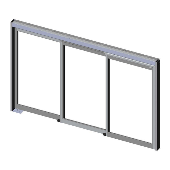
VersaMax
Besam ICU/CCU
Telescopic Equal Panel Installation Manual
Complies with applicable sections of NFPA 101 and the Life Safety Codes for Manually Operated
Pedestrian Doors.
US23-2101-02 Rev A
Issue 9-22-2011
Copyright 2010 - 2011 Beam US Inc., an ASSA ABLOY Group company. All rights reserved. Reproduction in whole or
in part without the express written permission of Besam US Inc. is prohibited.
Advertisement
Table of Contents

Related Manuals for Assa Abloy Besam VersaMax ICU


Summary of Contents for Assa Abloy Besam VersaMax ICU
- Page 1 Complies with applicable sections of NFPA 101 and the Life Safety Codes for Manually Operated Pedestrian Doors. US23-2101-02 Rev A Issue 9-22-2011 Copyright 2010 - 2011 Beam US Inc., an ASSA ABLOY Group company. All rights reserved. Reproduction in whole or in part without the express written permission of Besam US Inc. is prohibited.
- Page 2 Improperly adjusted doors can cause injury and/or equipment damage. Inspect door operation using Functional and Visual Inspection information in Owner’s Manual. Safety devices must be in place and operational. In this manual, the word: CAUTION - Means that personal injury or property damage can result from failure to follow instructions.
- Page 3 US23-2101-02 Rev A Issued: 9-22-2011 Page 3...
-
Page 4: Table Of Contents
Table of Contents Revisions ........................6 Important Information ....................8 Important Safety Instructions for Use ..................8 Environmental Requirements ....................8 Introduction ........................9 Models ........................... 9 Space Required ......................10 Installation Examples ....................11 Installation Requirements ..................12 Fastening Requirements ....................... 12 Tools Required ........................ - Page 5 Adjustments ........................ 35 Ball Catch and Detent Adjustment ..................35 PSA Arm Adjustment ......................36 Active Leaf Door Height Adjustment ..................37 Transfer Bracket – Belt Reconnect .................. 37 Flush Bolt Adjustment ......................38 Pre-Installation Check ......................38 Post-Installation Check ...................... 38 Telescopic Self Closing System –...
-
Page 6: Revisions
Revisions The following pages have been revised: Page Revision ------- ICU/CCU Telescopic Equal Panel Installation Manual, No. US23-2101-02, reissued: 9-22-2011 Updated PSA Adjustment process ------- Updated, Title pg, TOC, all footers and end page Page 6 Issued: 9-22-2011 US23-2101-02 Rev A... - Page 7 US23-2101-02 Rev A Issued: 9-22-2011 Page 7...
-
Page 8: Important Information
Important Information Important Safety Instructions for Use WARNING! It is important for the safety of persons to follow these instructions. (Save these instructions.) WARNING! To reduce the risk of injury, material damage and malfunction of the product, the instructions contained in this manual must be strictly observed during installation, adjustment, repairs, service, etc. -
Page 9: Introduction
Introduction This manual contains the necessary details and instructions for the installation, maintenance and service of the manual sliding door package, the Besam VersaMax ICU/CCU Telescopic Equal Panel package. The Besam ICU/CCU is designed for an overhead-concealed installation between two vertical jambs. The header, which is supported by the surrounding structure, supports the sliding doors and sidelites. -
Page 10: Space Required
Space Required Page 10 Issued: 9-22-2011 US23-2101-02 Rev A... -
Page 11: Installation Examples
Installation Examples US23-2101-02 Rev A Issued: 9-22-2011 Page 11... -
Page 12: Installation Requirements
Installation Requirements Fastening Requirements Base door / wall material Minimum Anchor Embedment* Steel 3/16" (5 mm)* Aluminum 1/4" (6 mm)* Reinforced concrete 1 1/2" (38 mm) from the underside Wood 1 1/2" (38 mm) Brick wall Expansion-shell bolt, min. (1/4" x 3 1/2"), min. 2" (50 mm) from the underside * Besam minimum recommended requirements. -
Page 13: Door Assembly Processes
Door Assembly Processes The door installation process incorporates, unpacking and installing hardware on the door panels. Unpacking It is important that all packing is removed from the door package so that it will not, later interfere with the operation of the door. Remove and dispose of all packaging and scrap materials in accordance with local regulations. -
Page 14: Smoke Seals (Optional)
Smoke Seals (Optional) US20-1627-02 On door packages that are provided with smoke seals, the smoke seals have been factory installed on the door stiles intentionally past the end of the doors. Trim door stile seals flush to stile ends prior to installing door panel. -
Page 15: Header, Jamb And Floor Track Assembly And Installation
Header, Jamb and Floor Track Assembly and Installation Rough Opening Inspection Check that there is sufficient material to adequately support and attach the Header using the factory-predrilled holes. The rough opening must be plumb and square and the finished floor must not vary by more than 1/4" from the highest to the lowest point. -
Page 16: Jamb And Header Assembly
Jamb and Header Assembly Besam jambs are factory prepared for header installation. Mount jambs to header using five screws per jamb. (Factory Provided.) Drill holes at the top, middle and bottom of the jambs for securing to the door opening, adjusting for site conditions that may require the holes to be at a certain height. -
Page 17: Leveling Header And Jambs
3. Drill holes through both the interior and exterior jamb wall and install beauty caps on the exterior holes. Leveling Header and Jambs Note! The header and jambs must be installed plumb, square and level to ensure proper door operation. 1. -
Page 18: Fitting The Floor Track
4. Check the position of the header; adjust side-to-side and front-to-back as needed, then clamp or temporarily fasten the assembly in place at the top of each jamb. Note! ICU Headers are not self-supporting and require overhead support for proper operation. Anchor holes will be pre-drilled at the factory in header to aid in installation. - Page 19 3. Using the measurements provided, lay the track in place, mark the holes, then remove track and drill for anchors. RECESSED TRACK (PIN GUIDE) Note! The G track is not to be mounted and leveled any lower than the bottom of the jamb and it must have an equal measurement from the top of the G track to the bottom of the header across its entire length.
-
Page 20: Installing The Pivot Plate (Trackless Application Only)
Installing the Pivot Plate (Trackless Application Only) Jamb Tube All trackless packages are a patent pending design. Pivot Washer 1. Place Pivot Plate on floor flush to Jamb Tube. Pivot Screw 2. Insert shims as required to level the Pivot Plate. Pivot Plate 3. -
Page 21: Track (Recessed) Installation
Track (Recessed) Installation FBO Sidelite Installation Procedure (Recessed Track Applications) Note! Remove packing material, if it has not already been removed from the sidelite before installation. 1. Remove Breakout tube. 2. Install and level any tracks (recessed) before installing any of the door panels. - Page 22 11. If the distance between the jamb and hinge stile needs to be adjusted, loosen the top and/or bottom sidelite pivot and slide left or right. Once adjusted properly, retighten screws. 12. Re-install the sidelite. 13. When all sidelite panels have been installed, tighten top pivot security set screw to prevent depressing the top pivot pin.
-
Page 23: Fbo Active Leaf #2 Installation Procedure (Track)
FBO Active Leaf #2 Installation Procedure (Track) Active Leaf in swung out position 1. Move inner carrier, for active leaf #2, away from sidelite. 2. With the Active Leaf #2 swung out away from carrier, slide Fig. A PSA arm into carrier so that it is recessed 1/4”. (See Fig. A.) 3. - Page 24 6. To adjust door height, loosen Wheel Bracket bolts & Anti- riser bolts and adjust door to proper height using the Adjustment Screw on the Wheel Brackets, taking into account the floor conditions for the full travel of the doors. When finished, tighten wheel bracket screws.
-
Page 25: Sidelite Removal Procedure
Sidelite Removal Procedure 1. Loosen Pivot Security set screw. Top View 2. Breakout sidelite to gain access to Top Pivot Pin located in the slot next to the pivot shaft. 3. Using a ¼” Allen Wrench key, and while supporting the sidelite, push down on the spring loaded Top Pivot Pin to disengage pivot. -
Page 26: Trackless Installation
Trackless Installation FBO Sidelite Installation Procedure (Trackless Applications) Caution! The Active Leaf should be installed with anti-risers before mounting sidelite, or hardware damage may occur. Note! Remove any packing material from the sidelite, if it has not already been removed, before installation. 1. - Page 27 FBO Sidelite Installation (Trackless) Top Pivot Pin (Spring Loaded) Pivot Security Screw Bottom Pivot Pin Bearing Washer US23-2101-02 Rev A Issued: 9-22-2011 Page 27...
-
Page 28: Fbo Active Leaf #2 Installation Procedure
FBO Active Leaf #2 Installation Procedure With the Pivot Block and Swing Arm already installed, move inner carrier, for active leaf #2, away from sidelite. (For Pivot Active Leaf in swung out position Block and Fixed Nose Guide information, reference Hardware Installation Section) - Page 29 16. To adjust door height, loosen Wheel Bracket bolts & Anti- riser bolts and adjust door to proper height using the Adjustment Screw on the Wheel Brackets, taking into account the floor conditions for the full travel of the doors. When finished, tighten wheel bracket screws.
-
Page 30: Fsl Installation Procedure
FSL Installation Procedure Note! Remove packing material from the sidelite, if it has not already been removed, before installation. 1. Remove Breakout Tube. 2. Place sidelite on "G" track. G Track 3. Line up the (2) connecting posts, located approximately 6" from each end of the top horizontal, with the (2) holes in the bottom of the header. -
Page 31: Fsl, Active Leaf #2 Installation Procedure
FSL, Active Leaf #2 Installation Procedure 1. Position #2 Leaf so the bottom roller guide wheels can be inserted into cutout in the bottom horizontal rail of sidelite. 2. Position #2 Leaf under the Carrier so that bolt holes in #2 Leaf line up with bolt holes in the Carrier as shown. -
Page 32: Fsl, Active Leaf #1 Installation Procedure
FSL, Active Leaf #1 Installation Procedure 1. Position #1 Leaf so the bottom roller guide wheels can be inserted into cutout in bottom horizontal rail of #2 Leaf. 2. Slide the #1 Leaf forward until PSA arm lines up with the #1 Leaf Carrier. - Page 33 7. Mark the position of the PSA arm in the Carrier. 8. Break #2 Leaf out enough to access the first screw (1) in PSA arm. 9. Make certain the rear of PSA arm is still on the mark and tighten PSA arm screw (1).
- Page 34 Anti-riser Bolt Wheel Bracket Bolts Adjustment Screw 16. The tension for the Ball Catch and Ball Detent are adjustable as required by local egress codes. The tension is not to exceed 50 lbs. breakout force. To adjust, use a 10 mm wrench on wrench flats to turn the Detent Assembly.
-
Page 35: Package Final Inspection And Adjustment
Package Final Inspection and Adjustment Door packages may be glazed before or after installation. Final adjustments and operational checks should be performed after all doors are installed and glazing, and installation of any trim and accessories are completed. Check clearances with floor and header in both sliding and break-out modes as well as sweep adjustment if applicable. -
Page 36: Psa Arm Adjustment
PSA Arm Adjustment 1. Open door and lock down #1 screw (pivoting set screw) of PSA arm, and loosen setscrews #3 and #4. 2. Adjust #2 screw (PSA vertical adjustment screw) on PSA arm to lift the door and ball catch lead edge into alignment with ball catch receiver. -
Page 37: Active Leaf Door Height Adjustment
Active Leaf Door Height Adjustment Note! Sidelite should be adjusted level and plumb with the proper 1/8” gap at the head before adjusting active leaf. 1. Loosen the two Wheel Bracket Screws and the anti-riser bolt on each side of the door. 2. -
Page 38: Flush Bolt Adjustment
Flush Bolt Adjustment The flush bolt assembly is factory installed and adjusted and should not require adjustment. Operation and function of the bolt should be checked at installation. Pre-Installation Check 1. Check operation by moving the level between the “LOCK” to the “UNLOCK”... -
Page 39: Telescopic Self Closing System - Set-Up & Adjustment
Telescopic Self Closing System – Set-up & Adjustment Introduction The self-closing system consists of three main components: (1) Spring Unit The spring unit provides the force to pull the door closed and is factory installed in the door header. Adjusting the spring tension affects the opening and closing force of the door panel. -
Page 40: Pinion Gear Height Adjustment
Fig. B Pinion Gear Height Adjustment Fig. A Gear Rack Position RIGHT HAND SHOWN, LEFT HAND OPPOSITE - ITEMS REMOVED FOR CLARITY 2. Check the spacing between the pinion gear and gear rack. A gap of between 2” and 4” is recommended. (Ref. Fig A) NOTE! Increasing the horizontal gap between the rack and pinion gears increases the latching force at low door speed. -
Page 41: Wedge Damper Adjustment
CAUTION! Belt and spring are under tension. Spring is pre-tensioned to hold the belt in place during shipment. 3. Hold the belt tail to prevent sudden release of spring tension, clip the belt tail zip tie. 4. Making certain there are no twists in the belt, grasp it with needle nosed pliers and slowly release tension while maintaining enough pressure to keep the belt tight on the pulleys. - Page 42 2. Spring pre-tension will affect latching force and also determines the closing force at the full open position. It is recommended to first adjust spring pre-tension to the minimum tension required to close the door from full open and then modify rack position and damper torque to achieve desired latching force and travel speed.
-
Page 43: Sweep Adjustment
Sweep Adjustment 1. If sweep(s) are included in your package, trim to length required for each panel. Note! The sweep will be longer than the sweep holder. Install sweep and holder into bottom of door as shown. 2. Insert sweep into Sweep Holder. 3. -
Page 44: Torsion Tube Adjustment (Large Doors)
Torsion Tube Adjustment (Large Doors) The Torsion Tube aids in aligning doors to jamb and is factory installed. 1. To adjust Torsion Tube, tighten set screws in pivot end block and loosen set screws in breakout end block. 2. Insert pry-bar through underside of carrier between tube and carrier wall at breakout end. -
Page 45: Glazing And Blocking
Glazing and Blocking Install glass using the proper glazing tools. Glass blocks are installed by door manufacturer. Please verify that glass block locations match graphic below. Observe standard glazing techniques when installing glass. CAUTION: If doors are not square, possible malfunction of doors and alignment issues may occur. -
Page 46: Part Identification And Options
Part Identification and Options Page 46 Issued: 9-22-2011 US23-2101-02 Rev A... - Page 47 Part Identification and Options (Continued) US23-2101-02 Rev A Issued: 9-22-2011 Page 47...
-
Page 48: Sidelite, Fsl (Fixed Sidelite)
Sidelite, FSL (Fixed Sidelite) Page 48 Issued: 9-22-2011 US23-2101-02 Rev A... -
Page 49: Active Leaf, Fsl (Fixed Sidelite)
Active Leaf, FSL (Fixed Sidelite) US23-2101-02 Rev A Issued: 9-22-2011 Page 49... -
Page 50: Sidelite, Fbo (Full Break Out)
Sidelite, FBO (Full Break Out) Page 50 Issued: 9-22-2011 US23-2101-02 Rev A... -
Page 51: Active Leaf, Fbo (Full Break Out)
Active Leaf, FBO (Full Break Out) US23-2101-02 Rev A Issued: 9-22-2011 Page 51... - Page 52 Page 52 Issued: 9-22-2011 US23-2101-02 Rev A...
- Page 53 NOTES US23-2101-02 Rev A Issued: 9-22-2011 Page 53...
- Page 54 Page 54 Issued: 9-22-2011 US23-2101-02 Rev A...
- Page 55 NOTES US23-2101-02 Rev A Issued: 9-22-2011 Page 55...
- Page 56 Fax: (704) 290-5544 1-877-BESAM-87 (877-237-2687) (service) 1-877-BESAM-87 (866-237-2687) (sales) Copyright 2010 - 2011 Beam US Inc., an ASSA ABLOY Group company. All rights reserved. Reproduction in whole or in part without the express written permission of Besam US Inc. is prohibited.
Need help?
Do you have a question about the Besam VersaMax ICU and is the answer not in the manual?
Questions and answers