Assa Abloy Besam SW300 Installation And Service Manual
Swing door operator
Hide thumbs
Also See for Besam SW300:
- User manual (414 pages) ,
- Installation and service manual (112 pages) ,
- User manual (270 pages)

Related Manuals for Assa Abloy Besam SW300


Summary of Contents for Assa Abloy Besam SW300
- Page 1 Installation and Service Manual Swing Door Operator Original instructions Besam SW300/SW150 ASSA ABLOY Entrance Systems...
- Page 2 Entrance Systems or companies within the ASSA ABLOY Group. © All rights in and to this material are the sole property of ASSA ABLOY Entrance Systems AB. Copying, scanning, alterations or modifications are expressly forbidden without the prior written consent of the applicable company within ASSA ABLOY Entrance Systems AB.
-
Page 3: Table Of Contents
Sync cable for double doors (synchronizing of 2 operators) ..................Coordination unit (only for Besam SW300) ......................... LED Cable ......................................Battery backup unit ..................................Double door kit ....................................Closing time board kit (only for Besam SW300) ......................... Fire kit (only for Besam SW300) ............................... Labels ......................................... 1007913-EI-9.0 Issue 2014-10-28... - Page 4 PULL arm system .................................... 11.3 Operator with sliding PUSH arm system ..........................11.4 Besam SW300 inverse installation with PUSH arm system ..................... 11.5 Besam SW300 inverse installation with PULL arm system ....................11.6 Installation of coordination unit on Fire Door installations ....................
- Page 5 Service/Maintenance ................................1007913-EI-9.0 Issue 2014-10-28...
-
Page 6: Revision
1 Revision Revision Following pages have been revised: Page Revision 8.0 → 9.0 Updated the article number. Issue 2014-10-28 1007913-EI-9.0... -
Page 7: Instructions For Safe Operation
2 Instructions for safe operation Instructions for safe operation • Failure to observe the information in this manual may result in personal injury or damage to equipment. • To reduce the risk of injury to persons - use this operator with single or double pedestrian swinging or folding doors only. -
Page 8: Important Information
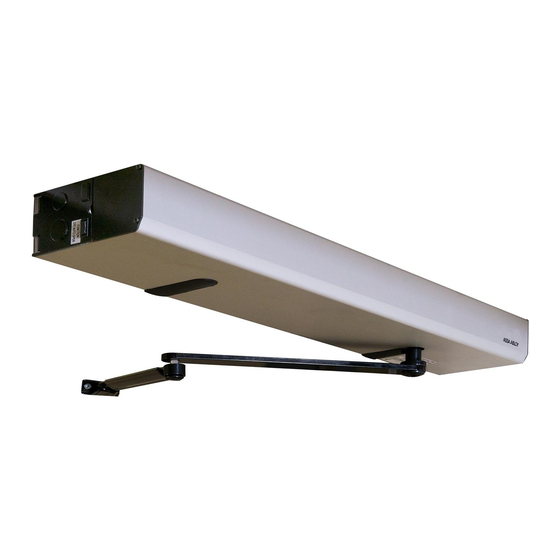
The Besam SW300/SW150 is an automatic swing door operator developed to facilitate entrances to buildings and within buildings through swing doors. The Besam SW300/SW150 is an electromech- anical operator approved for fire door applications. It is to be installed indoors where it is suitable for almost all types of external and internal swing doors. -
Page 9: Electronic Equipment Reception Interference
Environmental requirements ASSA ABLOY Entrance Systems products are equipped with electronics and may also be equipped with batteries containing materials which are hazardous to the environment. Disconnect power before removing electronics and battery and make sure it is disposed of properly according to local regulations (how and where) as was done with the packaging material. -
Page 10: Technical Specifications
4 Technical specifications Technical specifications Ensure that the door operator with technical specification below is suitable for the installation. Manufacturer: ASSA ABLOY Entrance Systems AB Address: Lodjursgatan 10, SE-261 44 Landskrona, Sweden Type: Besam SW300/SW150 Mains power supply: 100-240 V AC +10/-15%, 50/60 Hz, mains fuse max 10A (building... - Page 11 4 Technical specifications This product is to be installed internally. Besam SW300 Classification to DIN 18650-1 Operator Digit 1 Digit 2 Digit 3 Digit 4 Digit 5 Digit 6 Digit 7 Digit 8 Fire 1,2,3 0,1,2,3,4 0,1,2,3,4 Basic 1,2,3 0,1,2 0,1,2,3,4 Type of drive, digit 1.
-
Page 12: How The Besam Sw300/Sw150 Works
How the Besam SW300/SW150 works The swing door operator Besam SW300/SW150 uses a DC motor which is connected to the output shaft by a combination of a worm gear and spur gears. The push- or pull arm system that is connected to the output shaft opens the door in a surface mounted application. -
Page 13: Opening
5 How the Besam SW300/SW150 works Opening When an opening signal is received by the control unit, the door is opened at the operator-adjusted opening speed. Before the door is fully open at back check, it slows automatically to low speed. -
Page 14: Functions On The Basic Control Unit Cu-300
5 How the Besam SW300/SW150 works Functions on the basic control unit CU-300 See page 56 for more information. 5.4.1 Power failure During power failure the operator acts as a door closer with controlled closing speed and a micro switch will make a lock kick to secure latching (only fire rated version and no Inverse installation). -
Page 15: Mat
5 How the Besam SW300/SW150 works 5.4.9 Mat safety means that: • a closed door will not open, if someone steps on the mat • an open door will not close, if someone steps on the mat • during opening, the door will continue to open, even if someone steps on the mat •... -
Page 16: Functions On The Extension Unit Exu-Si
5 How the Besam SW300/SW150 works Functions on the extension unit EXU-SI Also see page 58 for more information. 5.5.1 KILL function In the event that the KILL circuit is activated, all Safety Functions of the door will be overridden causing the door to close even though an object or person may be in the door's path of travel, and therefore may be subject to injury. -
Page 17: Nurse And Bed Functionality
5 How the Besam SW300/SW150 works • DIP-switch for monitoring of batteries is also available. Faulty battery will be indicated by the LED on the CU-ESD. If selected the relay on EXU-SA can give a contact information. An audible warning signal can be achieved by using the accessory board AIU. It is connected to the 24 VDC and plugged into the EXU-SA relay output terminal. -
Page 18: Functions On The Extension Unit Exu-Sa
5 How the Besam SW300/SW150 works Functions on the extension unit EXU-SA Also see page 59 for more information. 5.6.1 Presence impulse approach, door mounted The presence impulse is active during fully open and closing. The sensor is mounted to the approach side of the door. -
Page 19: Models
6 Models Models Three main models of the Besam SW300/SW150 are available: • Single doors • Double doors (two operators) • Double egress doors (two operators) The operators are non-handed and not dependent on the hinges. The operators suit both pushing and pulling arm systems. -
Page 20: Double Operator, Surface Mounted
6 Models Double operator, surface mounted The product is delivered complete with back plate, control unit, end plates and cover. Total cover min. length CL = 1685 and max. 3300. Two operators can be mounted under the same cover (full length or a modular) to open one door each. -
Page 21: Part Identification
7 Part identification Part identification Item No. Art. No. Description Back plate 331009148 Transmission unit kit SW150 331007819PULL Transmission unit kit SW300 331007819PUSH Transmission unit kit SW300 331007819F Transmission unit kit SW300 (not for use in DE, GB and SE) 331008333 Control unit CU-300 without EXU-boards 331003554... - Page 22 7 Part identification Item No. Art. No. Description 331009105 Encoder cable 331009513 Fill cover Issue 2014-10-28 1007913-EI-9.0...
-
Page 23: Arm Systems
8 Arm systems Arm systems The installation process of arm systems is the same for Fire door installations, Basic installations and Inverse installations. Pushing installation with PUSH-arm This arm system is delivered with drive arm, telescopic part and door fitting. It is used if the oper- ator is installed on the wall on the opposite side of the door swing, and approved for fire door ap- plication for A up to 300 mm. -
Page 24: Pulling Installation With Pull-Arm
8 Arm systems Pulling installation with PULL-arm This arm system is delivered with drive arm, guide shoe and door fitting. Approved for fire door application for A up to 130 mm. Slim slide track PULL, Art. no.:1008401BK, 1008401SI Slim slide track PULL-220, Art.no.:1011998BK, 1011998SI A = 0-130 150 mm Issue 2014-10-28... -
Page 25: Pushing Installation With Pull-Arm
8 Arm systems Pushing installation with PULL-arm This arm system consists of main arm, slide track, guide shoe and shaft adaptor. It can be fitted on combinations of doors and jambs (walls), where the wall thickness does not exceed approx. 114 mm. -
Page 26: Options
SLAVE Black Art. No. 1003583 Coordination unit (only for Besam SW300) To coordinate rebated doors in a double door installation and to make sure the doors are closed in right order. See page 51 for installation and adjustment. Art. No. -
Page 27: Led Cable
Art. No. 1007823 Double door kit Art. No. 1009686 Closing time board kit (only for Besam SW300) To fulfill the DIN 18263-4 standard it is necessary to mount and connect this board to the lock kick. Art. No: 1010374 1007913-EI-9.0... -
Page 28: Fire Kit (Only For Besam Sw300)
9 Options Fire kit (only for Besam SW300) For fire door installations. Art. No: 1009899 Labels Label kit- including all below Art. No.1005227 Emergency break-out, DIN right door Emergency break-out, DIN left door Click! Activation by disabled people Operator designed for disabled people... -
Page 29: Pre-Installation
10 Pre-installation Pre-installation 10.1 General tips/Safety concerns 10.1.1 General tips/Safety concerns In all instances, where work is being done, the area is to be secured from ped- estrian traffic, and the power removed to prevent injury. • If there are sharp edges after drilling the cable outlets, chamfer the edges to avoid damage to the cables. -
Page 30: Installation Examples
10 Pre-installation 10.3 Installation examples Non combustible material in fire ap- plication Non combustible material in fire application Aluminium profile system Steel reinforcement or rivnut Plasterboard wall Wood reinforcement Reinforced concrete wall and brick wall Expansion-shell bolt (for brick wall min. M6x85, UPAT PSEA B10/25) Plasterboard wall 10.4... -
Page 31: Tools Required
10 Pre-installation 10.5 Tools required • Metric Allen keys 1.5; 2.5; 3; 4; 5 and 6 mm • Torque wrench • Allen key 1.5; 2.5 and 3 mmwith spherical tip • Torx Torx T10 • Tool for screw between cover and backplate •... -
Page 32: Mechanical Installation
11 Mechanical installation Mechanical installation The operator is mounted on either side of the door header depending on type of doors. The door is controlled with a push or pull arm system. If a coordination unit is to be installed on a double door installation, mount the coordinator base with rotor before mounting the control unit, see page 51. - Page 33 11 Mechanical installation Make sure to mount the drive unit at measurement A and the control unit at measurement B. The illustrations also show how to route the cables. If there are sharp edges after drilling the cable outlets, chamfer the edges to avoid damage to the cables. A = 192 B = 557 1007913-EI-9.0...
- Page 34 11 Mechanical installation A = 192 B = 557 Issue 2014-10-28 1007913-EI-9.0...
- Page 35 11 Mechanical installation A = 192 B = 557 150 mm 42 mm 1007913-EI-9.0 Issue 2014-10-28...
-
Page 36: Push Arm System
11 Mechanical installation 11.1 PUSH arm system PUSH 35 mm Shaft extension Shaft extension 48 mm 51 mm 2-25 mm 2 - 14 mm 15 - 35 mm 25-45 mm 71 mm 68 mm 20 mm 20 mm Reveal 36 - 65 mm 98 mm 50 mm 45-75 mm... - Page 37 11 Mechanical installation Operator with PUSH arm system DIN Right DIN Right (mm) (mm) C L 1 1007913-EI-9.0 Issue 2014-10-28...
- Page 38 11 Mechanical installation Cont."Operator with PUSH arm system" DIN Left DIN Left (mm) (mm) C L 1 C L 2 C L 1 C L 2 Issue 2014-10-28 1007913-EI-9.0...
- Page 39 DIN Left DIN Right DIN Right DIN Left 20° 1. Pre-tension the spring Note! Only Besam SW300, not Besam SW150 2. Secure the pre-tension by the pin Let the stop arm locator and the stop arm be loose. Do not tighten.
- Page 40 11 Mechanical installation Cont."Operator with PUSH arm system" MARK Align the arm with the operat- Align the marks between arm or mark. and adaptor. 15 Nm Loosen the four screws. Fasten the arm system to the door. Issue 2014-10-28 1007913-EI-9.0...
- Page 41 11 Mechanical installation 10 lbf·ft (14 Nm) 14 Nm Tighten the four screws. The door must be closed. XIII Hold the door a bit open and remove the start posi- tion pin. 50 Nm 50 Nm See the table on page 23 for available extensions. Continue on page 54.
-
Page 42: Pull Arm System
11 Mechanical installation 11.2 PULL arm system Slim slide track PULL 35 mm 48 mm 48 mm 20 mm 68 mm 20 mm 68 mm 50 mm 98 mm 50 mm 98 mm 10 mm 70 mm 118 mm 70 mm 118 mm A = 0-130 Issue 2014-10-28... - Page 43 11 Mechanical installation Operator with PULL arm system DIN Left DIN Left (mm) (mm) C L 1 1007913-EI-9.0 Issue 2014-10-28...
- Page 44 11 Mechanical installation Cont. Operator with PULL arm system DIN Right DIN Right (mm) (mm) 6 5 2 C L 1 C L 2 C L 1 C L 2 Issue 2014-10-28 1007913-EI-9.0...
- Page 45 11 Mechanical installation Cont. "Operator with PULL arm system" DIN Right DIN Right DIN Left DIN Left 20° Note! Only Besam SW300, not Besam SW150 Let the stop arm locator and the stop arm be loose. Do not tighten. 1007913-EI-9.0 Issue 2014-10-28...
- Page 46 11 Mechanical installation Slim slide track Attach the slide track (1) to the door with the guide shoe (2) fitted into the track. Use appropriate screws. Click Click Slide track Guide shoe Issue 2014-10-28 1007913-EI-9.0...
- Page 47 11 Mechanical installation Cont. "Operator with PULL arm system" It is important to align the marks correctly. If necessary move one mark at a time. This corresponds to approx. 3° and will give a precision of ±1,5°. Align the marks. VIII 50 Nm 50 Nm...
-
Page 48: Operator With Sliding Push Arm System
114 mm See instructions for PULL installation. 11.4 Besam SW300 inverse installation with PUSH arm system Remove the microswitch lever (1). Note! Set dip switch INV to ON for Inverse operation, see 12.1.1 on page 56. If higher opening speed is required at power failure, add board 1010374. -
Page 49: Besam Sw300 Inverse Installation With Pull Arm System
If necessary, adjust by moving the adaptor one step at a time. 11.5 Besam SW300 inverse installation with PULL arm system Remove the microswitch lever (1). Note! Set dip switch INV to ON for Inverse operation, see 12.1.1 on page 56. - Page 50 11 Mechanical installation Follow step in on page 43, with the difference that the operator is turned 180° so the "INVERSE" text on the operator is visible and do not make step 50 Nm Open the door in fully open position. Tighten the adaptor fixing screw.
-
Page 51: Installation Of Coordination Unit On Fire Door Installations
11 Mechanical installation 11.6 Installation of coordination unit on Fire Door installations Mount the rotor (parts 1 to 4 below) before the motor is installed on the back plate. Install the control unit when the installation of the coordination unit is completed. If the coordination unit will be installed on an existing installation it is possible to move the control unit a little bit to be able to reach the motor unit during installation. - Page 52 11 Mechanical installation e Release the brake, by pushing in the forks so that the brake is opening, before mounting the coordinator base (14) with the two screws (7) on the master drive unit. Remove the screw (8) and mount the acceptor (10) on the adjuster (9). Mount the screw (8) through the acceptor (10).
- Page 53 11 Mechanical installation h Adjust the release of the brake by loosening the joint (17) and turning the link rod (11) close to the master drive unit. Make the angle between the doors near closed position. Adjust the braking torque to >50 Nm measured on the door leaf by turning one or both screws (18).
-
Page 54: Electrical Connection
12 Electrical connection Electrical connection Note! During any work with the electrical connections the mains power must be disconnected. • Place the electric switch easily accessible from the operator. • The operator is intended for fixed installation only with cable entry from the backplate. It is not designed for cable entry from the side plates. - Page 55 12 Electrical connection Alt.2 (Optional) Alt.3 (Optional) Alt.4 (Optional) 1007913-EI-9.0 Issue 2014-10-28...
-
Page 56: Control Units
12 Electrical connection 12.1 Control units 12.1.1 CU-300 Synchronizing of double doors Hold open time Key hold open time Encoder Closing torque DIP-switch Program selector Motor PUSH 2 3 4 5 6 7 Motor +24V DC PULL 1.5 s 30 s HOT / KHOT = Lock-out for OPD (–) LOUT... -
Page 57: Extension Units Exu-Si / Exu-Sa
12 Electrical connection 12.1.3 Extension units EXU-SI / EXU-SA Torx T10 EXU-SA 5 mm nut driver Electrical power contact EXU-SI Tag strip long 2 pcs EXU short 1 pc EXU CU-300 1007913-EI-9.0 Issue 2014-10-28... -
Page 58: Extension Unit Exu-Si
12 Electrical connection 12.1.4 Extension unit EXU-SI Functions This extension unit has inputs for electro-mechanical lock, program selector, KILL function, OPEN/CLOSE, KEY opening and outer impulse. +24 V DC (+) 24 VDC OPEN Program selector EXIT Unlocked signal from lock KRST KILL reset (see jumper below) KILL impulse... -
Page 59: Extension Unit Exu-Sa
12 Electrical connection 12.1.5 Extension unit EXU-SA This extension unit has inputs for door mounted sensors, which can give presence impulse on ap- proach side and/or presence detection on swing path side. Relay output for error indication, KILL output, Lock output or door indication is also integrated. When the jumper for the relay is set to ‘Open/Closed door indication’, its activation will follow the Blanking LED. -
Page 60: How To Cut The Jumper On The Sync Cable For Double Doors
12 Electrical connection 12.1.6 How to cut the jumper on the sync cable for double doors MASTER SLAVE Black Note! The connection/marking of the sync cable determines which of the operators is the MASTER and SLAVE. For an Astragal door; •... -
Page 61: Settings For Double Doors
12 Electrical connection 12.1.8 Settings for double doors Settings on the Function MASTER SLAVE Common Program selection Opening time Closing time Hold open time Close / Continue to open when the door is obstructed PAG On/Off Level of Power assist (X)* Extended closing force (X)*... -
Page 62: Sensor Cable Inlet
12 Electrical connection 12.2 Sensor cable inlet Art. No. 1007567 Alt. 1 Alt. 1 Alt. 2 Alt. 2 ø 3,7 Issue 2014-10-28 1007913-EI-9.0... -
Page 63: Reset And Indication Device For Fire Doors
12 Electrical connection 12.3 Reset and indication device for Fire Doors Art. No. 1009828 CL=840 CL=Optional CL=840 CL=Optional Reset & Indication device Reset & Indication device B Smoke detector Smoke detector ø 3,7 1007913-EI-9.0 Issue 2014-10-28... - Page 64 12 Electrical connection CU-300 Master CU-300 Master 2 3 4 5 6 7 ALARM (red) OK (green) OK Green ALARM (red) EXU-SI Master EXU-SI Master NC Kill switch (Parameter group 13) NC Kill switch Fire alarm reset Fire alarm reset Kill switch and close Kill switch and Reset &...
-
Page 65: Start-Up
Start-up 13.1 Besam SW300 spring pre-tension The spring pre-tension is factory set to EN4. The closing torque (spring force) is adjusted by an hexagon nut placed at the end of the spring. Turning the nut clockwise increases the force. One turn equals a torque change of approx. -
Page 66: Micro Switch (Only For Besam Sw300)
13 Start-up 13.2 Micro switch (only for Besam SW300) Check and adjust the micro switch, controlling the lock kick at power failure. 13.3 Adjusting the door stop a Close the door. b Open the door to required open position, plus approx. 15 mm. Put a doorbuffer under the door. - Page 67 13 Start-up d When stop arm is on the bottom of the operator, loose the stop arm locator and the stop arm. Mount the stop arm on the splines, as close as possible to the stop block 3). Mount the stop arm locator.
-
Page 68: Auto-Learn Automatically Sets Back And Latch Check (Recommended)
13 Start-up 13.4 Auto-learn automatically sets back and latch check (recommended) This learning is performed by pushing the LEARN BUTTON (LRN). • Switch on the electrical power (the operator will find its closed position) and make sure the LED is on. •... -
Page 69: Push The Learn Button (Lrn)
13 Start-up 13.4.1 Push the LEARN BUTTON (LRN) The door has no safety during auto-learn cycle. Remain clear of swing path of door, as door may close rapidly. When the learn button is pressed the status LED starts to blink and will not stop until learn is con- cluded. -
Page 70: Connection Of Activation Units And Accessories
13 Start-up 13.6 Connection of activation units and accessories See sensor manuals for mounting and adjustments. Protective device shall comply with EN 12978. Door mounted When sensors are used in order to avoid contact with the door leaf it is required that the presence detect sensor and the presence im- pulse sensor fulfills Performance Level = c according to EN ISO 13849-1. - Page 71 13 Start-up Fire alarm reset Black Standard 1007913-EI-9.0 Issue 2014-10-28...
-
Page 72: Changing Group Of Parameters
14 Changing group of parameters Changing group of parameters a Disconnect batteries if any. b Disconnect the electrical power contact. c Press the LEARN BUTTON (LRN) and keep it depressed. d Connect the electrical power contact. e Watch the ERROR LED. Release the LEARN BUTTON after the 5 seconds (LED is out). - Page 73 14 Changing group of parameters 1007913-EI-9.0 Issue 2014-10-28...
- Page 74 14 Changing group of parameters Issue 2014-10-28 1007913-EI-9.0...
-
Page 75: Learn With Advanced Setting Of "Back- And Latch-Check
14 Changing group of parameters 14.1 Learn with advanced setting of “back- and latch-check” See the prerequisites for performing a “learn” in section Auto-learn automatically sets back and latch check (recommended) on page 68. a Push the button once as for auto-setting. Text 'LEARN' will show on the display. -
Page 76: Classification
15 Classification Classification 15.1 Entering the program mode (classification) If the operator is equipped with batteries, they must be disconnected before the following procedure is preformed. • Disconnect the mains plug • Press the LEARN BUTTON while connecting the mains plug •... - Page 77 15 Classification Speed settings for Low energy mode The table shows minimum opening time to back check or to 80° open or minimum closing time from 90° to 10° open. Width of door leaf (mm) Door mass (kg) Time (s) minimum 1000 1200 1007913-EI-9.0...
-
Page 78: Cover
16 Cover Cover The cover and back plate are manufactured in clear anodized aluminium. The end plates are made of black painted steel sheet. 16.1 Fitting and removing the cover The cover is slid over flanges in the back plate so that the ridges fit in the grooves. Snap on the fill cover into the slot for output shaft. -
Page 79: Signage
Emergency break-out: Mandatory, if approved for escape route. ASSA ABLOY Entrance Systems door sticker: Mandatory according to ASSA ABLOY Entrance Systems brand instructions, European directives and equivalent national legislation outside the European Union, to highlight the presence of the glass. -
Page 80: Guide For Installation And Adjustments
18 Guide for installation and adjustments Guide for installation and adjustments 18.1 Complementary Safety Devices Swing Doors If there is any risk for finger jam, add finger protection strip at the hinge side for internal doors, article No. 833334 or add finger protection roll for external doors, article No. 833333. 18.2 Swing Doors Opening and Closing Time Adjust, as a minimum, the operator's opening and closing time according to the diagram below. -
Page 81: Diagrams For Door Weight
18 Guide for installation and adjustments 18.3 Diagrams for Door weight a Measure the door width (DW) and the door height (DH) in metres for one door leaf only. b Calculate the area DW x DH. c Select diagram for your type of door and the actual glass thickness. Find the weight. Example: Aluminium door with measurement DW = 1.5 m, DH = 2 m and glass thickness 12 mm. -
Page 82: Troubleshooting
19 Troubleshooting Troubleshooting Fault Possible reasons why Remedies/Explanations The door does not open Control switch is set to OFF Change the setting of the control switch The motor does not start Electrical power is missing Check the electrical power power switch Activation unit does not function Strap impulse inputs Presence detection is activated... -
Page 83: Error Indication
19 Troubleshooting 19.1 Error indication • During normal operation the ERROR LED on the control unit is illuminated. • An extinguished LED indicates that there is no electrical power. • A flashing light on the LED indicates that the operator is out of function (see table below). •... - Page 84 Service/Maintenance Regular inspections shall be made according to national regulations and product documentation by a ASSA ABLOY Entrance Systems-trained and qualified technician. The number of service occasions should be in accordance with national requirements and product documentation. This is especially important when the installation concerns a fire-approved door or a door with an emergency opening function.
- Page 85 ASSA ABLOY Entrance Systems is a leading supplier of entrance automation solutions for efficient flow of goods and people. With our globally recognized product brands Besam, Crawford, Megadoor and Albany, we offer products and services dedicated to satisfying end-user needs for safe, secure, convenient and sustainable operations.
Need help?
Do you have a question about the Besam SW300 and is the answer not in the manual?
Questions and answers