Danfoss AK-CC55 Multi Coil User Manual
Case/room controller (eev)
Hide thumbs
Also See for AK-CC55 Multi Coil:
- User manual (71 pages) ,
- Installation manual (18 pages) ,
- User manual (69 pages)

Subscribe to Our Youtube Channel
Related Manuals for Danfoss AK-CC55 Multi Coil


Summary of Contents for Danfoss AK-CC55 Multi Coil
- Page 1 User Guide Case/room controller (EEV) Type AK-CC55 Multi Coil SW Ver. 1.9x For refrigeration appliances and cold storage rooms.
-
Page 2: Table Of Contents
Start of defrost Stop of defrost Defrost sequence Real-time clock Coordinated defrost Melt function Rail heat Fan pulse control Light function Night blind Humidity control Heating function (application 4 only) © Danfoss | Climate Solutions | 2022.08 BC365022028193en-000201 | 2... - Page 3 Get a good start AK-UI55 display menu (SW ver. 1.9x) Thermostat Alarm settings Defrost Injection control Fan control Defrost schedule Humidity control Miscellaneous Control DO config and manual Service Operation via AK-UI55 Bluetooth © Danfoss | Climate Solutions | 2022.08 BC365022028193en-000201 | 3...
- Page 4 Technical data Electrical specifications Sensor and measuring data Input and output relay specifications Function data Environmental conditions Dimensions Ordering Certificates, declarations, and approvals Statements for the AK-UI55 Bluetooth display Online support © Danfoss | Climate Solutions | 2022.08 BC365022028193en-000201 | 4...
-
Page 5: Introduction
Figure 1: AK-CC55 with evaporator, AKV valve and sensor positions S4/S4B/S4C S2/S2B/S2C S5/S5B Hint: On cold rooms the S4 sensor can be placed at the air inlet of the evaporator. © Danfoss | Climate Solutions | 2022.08 BC365022028193en-000201 | 5... -
Page 6: Portfolio Overview
Heating function Control of air humidity Adaptive superheat Adaptive liquid control (zero superheat control for transcritical CO systems with liquid ejectors) Adaptive defrosting Product sensor Oil recovery RS485 Lon, option (AK-OB55) © Danfoss | Climate Solutions | 2022.08 BC365022028193en-000201 | 6... -
Page 7: Connectivity
The controller has built-in MODBUS data communication. If there is a requirement for a different form of data communication, a Lon RS 485 module can be inserted in the controller. The connection must then be to the module. Figure 3: Mounting of communication module © Danfoss | Climate Solutions | 2022.08 BC365022028193en-000201 | 7... -
Page 8: Ak-Cc55 Multi Coil
AK-CC55 Multi Coil AK-CC55 Multi Coil AK-CC55 Multi Coil – Controlling up to 3 AKV valves. An application mode setting will configure inputs and outputs for the desired use. There are five applications to choose from. Standard enclosure. Typically used for display cases where the controller is mounted in a tray. -
Page 9: Controller Functionality
This type of control requires that the controller receives an on/off signal from (for example) a suction accumulator in the suction line. © Danfoss | Climate Solutions | 2022.08 BC365022028193en-000201 | 9... -
Page 10: Temperature Control
Accidental actuation may allow liquid throughput to the compressor. It is the installer’s responsibility to ensure that signal loss to the controller will not result in liquid throughput to the compressor. Danfoss accepts no responsibility for damage resulting from inadequate installation. -
Page 11: Thermostat Bands
A sensor point is defined by setting a temperature value and the corresponding resistance value at this temperature. The resistance value is set via two values for kohm and ohm respectively. These values can be found in the data sheet for the sensor. © Danfoss | Climate Solutions | 2022.08 BC365022028193en-000201 | 11... -
Page 12: Appliance Cleaning
A user defined temperature sensor can only be be defined within the temperature range from -40 – +60 °C and within the resistance range from 400 – 179.999 ohm. When applying a new user defined sensor type, please contact Danfoss for validation of compliance and measuring accuracy. -
Page 13: Appliance Shutdown
Here defrost can be started at fixed times of the day and night. However, max. 6 defrosts per day. Contact: Defrost is started with a contact signal on a digital input. © Danfoss | Climate Solutions | 2022.08 BC365022028193en-000201 | 13... -
Page 14: Stop Of Defrost
During an electrical defrost sequence where the defrost heater is ON during defrost, AKV valve is closed and fans are running during defrost but stopped during drip. Fan control during defrost During the defrost sequence, the evaporator fans can be controlled in one of the following ways: © Danfoss | Climate Solutions | 2022.08 BC365022028193en-000201 | 14... -
Page 15: Real-Time Clock
The controller has a built-in real-time clock which can be used to start defrosts. This clock has a power reserve of four days. If the controller is equipped with data communication, the clock will automatically be updated from a Danfoss system manager. -
Page 16: Fan Pulse Control
Pulse control can be accomplished in one of the following ways: • during the thermostat’s cut-out period (cold room) • during night operation and during the thermostat’s cut-out period (appliance with night blinds) © Danfoss | Climate Solutions | 2022.08 BC365022028193en-000201 | 16... -
Page 17: Light Function
In application 4 when setup for room control it is possible to define if humidity control should be done via a humidifier or a dehumidifier. When humidity control is enabled, the second display will read out the actual humidity. © Danfoss | Climate Solutions | 2022.08 BC365022028193en-000201 | 17... - Page 18 If the humidity gets below the SP, then humidification is started via a DO signal to a humidifier. If the humidity increases to SP + humidity differential, then humidification is stopped. © Danfoss | Climate Solutions | 2022.08 BC365022028193en-000201 | 18...
-
Page 19: Heating Function (Application 4 Only)
There are two digital inputs, DI1 and DI2, with dry contact function, and one digital input DI3 with high voltage signal. They can be used for the following functions: Table 5: Function table and DI settings Input / Settings menu Function Setting None DI Status Door function Door alarm © Danfoss | Climate Solutions | 2022.08 BC365022028193en-000201 | 19... -
Page 20: Forced Closing
Display The controller has one or two plugs for an external display. One of the following display types can be connected to a plug: © Danfoss | Climate Solutions | 2022.08 BC365022028193en-000201 | 20... -
Page 21: Override
Master control signal sending the actual measured dewpoint from the system manager to the controller over the network. Master control signal that will lock down all Bluetooth data communication and optionally also lock the display keyboard (parame- MC Key/Bluetooth lock ter P89) © Danfoss | Climate Solutions | 2022.08 BC365022028193en-000201 | 21... -
Page 22: Applications
Max. 0.5 A - No overload protection! AK-CC55 Multi Coil is optimised for control of one to three expansion valve + different combinations of light, rail heat and alarm relays. It has 7 Digital Outputs (DO), known as DO1 – DO7, one Analogue Output (AO), known as AO1, 6 Analogue Inputs (AI), known as AI1 –... -
Page 23: Application Set-Ups And Io Connections
AK-CC55 Multi Coil Table 8: AK-CC55 Multi Coil Application with Digital and Analogue output specification Application description 1 evaporator 2 evaporators 3 evaporators Cold room Cold room Table 9: Sensor description Evaporating pressure S2 A, B or C Gas outlet of evaporator A, B or C... - Page 24 115 – 230 V AC AKV A Alarm AKV B Humidity Light Heat 115 – 230 V AC 10 11 12 13 14 15 16 17 18 19 23 24 © Danfoss | Climate Solutions | 2022.08 BC365022028193en-000201 | 24...
-
Page 25: Product Identification
AK-CC55 Multi Coil connections Data communication Figure 34: Data communication IMPORTANT: It is important that the installation of the data communication cable is performed correctly with sufficient distance to high voltage cables. © Danfoss | Climate Solutions | 2022.08 BC365022028193en-000201 | 25... -
Page 26: Akv Info
AKS 32R info Figure 39: AKS 32R info Black AKS 32R Brown Blue NOTE: A ratiometric pressure transmitter with a 5 V, 10 – 90% voltage output signal must be used. © Danfoss | Climate Solutions | 2022.08 BC365022028193en-000201 | 26... -
Page 27: Coordinated Defrost Via Cable Connections
• Analogue 0 – 10 V (currently not used) • Pulse width modulated signal Can be used for fast pulse control of rail heat via an external power solid state relay. © Danfoss | Climate Solutions | 2022.08 BC365022028193en-000201 | 27... - Page 28 Electronic controls are no substitute for normal, good engineering practice. Danfoss will not be responsible for any goods, or plant components, damaged as a result of the above defects. It is the installer's responsibility to check the installation thoroughly, and to fit the necessary safety devices.
-
Page 29: Operation
The display keys will be locked and unlocked by means of a master control signal from the System Manager. © Danfoss | Climate Solutions | 2022.08 BC365022028193en-000201 | 29... - Page 30 • When FAc is shown in the display, select "yes" NOTE: The OEM factory setting will either be the Danfoss factory settings or a user defined factory setting if one has been made. The user can save his setting as OEM factory setting via parameter o67.
-
Page 31: Parameter Groups When Operating Via Display
Then select a set of presets from the "Food type" help table Open parameter r89 and set the number for the array of presettings. The few selected settings will now be transferred to the menu © Danfoss | Climate Solutions | 2022.08 BC365022028193en-000201 | 31... - Page 32 14 °C 8 °C 8 °C -15 °C -15 °C Lower alarm limit (A14) 0 °C -5 °C -5 °C -30 °C -30 °C Can only be set when r12=0. © Danfoss | Climate Solutions | 2022.08 BC365022028193en-000201 | 32...
-
Page 33: Ak-Ui55 Display Menu (Sw Ver. 1.9X)
Low alarm limit 2 -60.0 °C 50.0 °C -30.0 °C Alarm delay DI 1 0 min 240 min 30 min Alarm delay DI 2 0 min 240 min 30 min © Danfoss | Climate Solutions | 2022.08 BC365022028193en-000201 | 33... -
Page 34: Defrost
Def. start 4 - Hours 0 hours 23 hours 0 hour Def. start 4 - min 0 min 59 min 0 min Def. start 5 - Hours 0 hours 23 hours 0 hour © Danfoss | Climate Solutions | 2022.08 BC365022028193en-000201 | 34... -
Page 35: Humidity Control
Temperature sensor type 0=Pt 1000, 1=PTC 1000, 2=NTC 5k, 3=NTC 10k, 4=User-defined Max. hold time 0 min 360 min 20 min Pe Min range -1.0 Bar 5.0 Bar -1.0Bar Pe Max range 6.0 Bar 200.0 Bar 12.0Bar © Danfoss | Climate Solutions | 2022.08 BC365022028193en-000201 | 35... - Page 36 In order to change this parameter the regulation must be stopped via the parameter r12 Main switch = OFF. In order to change this parameter the regulation must be stopped via the parameter r12 Main switch = OFF. © Danfoss | Climate Solutions | 2022.08 BC365022028193en-000201 | 36...
-
Page 37: Control
S4 Air OFF evap. B - Adjustment -10.0 °C 10.0 °C 0.0 °C S4 Air OFF evap. C - Adjustment -10.0 °C 10.0 °C 0.0 °C Dehumidifier -override 0=MAN OFF, 1=MAN ON © Danfoss | Climate Solutions | 2022.08 BC365022028193en-000201 | 37... -
Page 38: Service
100 % Humidifier 0=OFF, 1=ON Rail heat PWM 100 % Food temperature A -200.0 °C 200.0 °C 0.0 °C Defrost sensor tempera- -200.0 °C 200.0 °C 0.0 °C ture A © Danfoss | Climate Solutions | 2022.08 BC365022028193en-000201 | 38... - Page 39 -200.0 °C 200.0 °C 0.0 °C Defrost sensor tempera- -200.0 °C 200.0 °C 0.0 °C ture B Defrost sensor tempera- -200.0 °C 200.0 °C 0.0 °C ture C Dehumidifier 0=OFF, 1=ON © Danfoss | Climate Solutions | 2022.08 BC365022028193en-000201 | 39...
-
Page 40: Operation Via Ak-Ui55 Bluetooth
• The operation is locked and cannot be operated via Bluetooth. • Unlock from the system manager. Figure 46: Connect to controller Figure 47: Controller dashboard Figure 48: Set-up menu The functions are described on Page 41 – Page © Danfoss | Climate Solutions | 2022.08 BC365022028193en-000201 | 40... -
Page 41: Ak-Cc55 Connect Menu (Sw Ver. 1.9X)
28=R744, 46=R1233zdE, 38=R1234ze, 39=R1234yf, 47=R1234zeZ, 29=R1270, 42=R452A, 1=User defined display, 13=User defined Refrigerant factor K1 Refrigerant factor for a custom refrigerant - please P83 RfgFac.K1 contact Danfoss for detailed information © Danfoss | Climate Solutions | 2022.08 BC365022028193en-000201 | 41... - Page 42 ON. IMPORTANT: Before you set o04, you MUST set the application mode of the controller (The function is not used when the data communication is MODBUS) © Danfoss | Climate Solutions | 2022.08 BC365022028193en-000201 | 42...
-
Page 43: Thermostat Control
Select which sensor to be used for the thermostat 1=Ther. air A, 2=Average all, 3=Maximum all r99 Ther. sensor control Cut-out 1 Setpoint. The thermostat’s cut-out value when the r00 Cutout given thermostat band is in use © Danfoss | Climate Solutions | 2022.08 BC365022028193en-000201 | 43... -
Page 44: Alarm Limits And Delays
25=Manual control, 26=No refrigerant selec- ted, 29=Case cleaning, 30=Forced cooling, 31=Door open, 32=Power-up delay, 33=Air heating, 45=Shut down controller, 48=Adaptive liquid control Alarm air temp. A Measured temperature for alarm thermostat u57 Alarm air © Danfoss | Climate Solutions | 2022.08 BC365022028193en-000201 | 44... - Page 45 Alarm delay DI 1 Time delay for digital input alarm A27 Al.Delay DI1 Alarm delay DI 2 Time delay for digital input alarm A28 Al.Delay DI2 © Danfoss | Climate Solutions | 2022.08 BC365022028193en-000201 | 45...
-
Page 46: Humidity Control
(frost limit) Humidity min. temp. Minimum limit for thermostat air temperature in or- h33 RH Min temp. der for humidity control to run (frost limit) © Danfoss | Climate Solutions | 2022.08 BC365022028193en-000201 | 46... -
Page 47: Injection Control
U79 S2 temp. B Superheat B Readout of actual superheat at the outlet of the evap- U80 Superheat B orator Superheat reference Readout of the actual superheat reference U81 SH Ref B © Danfoss | Climate Solutions | 2022.08 BC365022028193en-000201 | 47... -
Page 48: Defrost Control
Defrost time tion of the last completed defrost. Defrost time B Read the duration of the ongoing defrost or the dura- U75 Def. Time B tion of the last completed defrost. © Danfoss | Climate Solutions | 2022.08 BC365022028193en-000201 | 48... - Page 49 If this signal fails to appear for one reason or another, the controller itself will start the refrigeration when the standby time has elapsed. © Danfoss | Climate Solutions | 2022.08 BC365022028193en-000201 | 49...
-
Page 50: Defrost Schedules
Thursday - Follow 0=No, 1=Yes t54 Thu.Schedule schedule Friday - Follow 0=No, 1=Yes t55 Fri.Schedule schedule Saturday - Follow 0=No, 1=Yes t56 Sat.Schedule schedule Sunday - Follow 0=No, 1=Yes t57 Sun.Schedule schedule © Danfoss | Climate Solutions | 2022.08 BC365022028193en-000201 | 50... -
Page 51: Fan Control
Fan stop at blinds When blinds are closing the fans are stopped in the P65 BlindFanStop closing defined time delay in order to ensure that the blinds are closed correctly © Danfoss | Climate Solutions | 2022.08 BC365022028193en-000201 | 51... -
Page 52: Railheat Control
DewP Min lim rail heat is running at minimum heat Dewpoint max. limit If the measured dewpoint is above the set value the o87 DewP Max lim rail heat is maximum © Danfoss | Climate Solutions | 2022.08 BC365022028193en-000201 | 52... -
Page 53: Light/Cleaning Control
Readout of the temperature shown on the display U35 Display air2 Display readout Select which temperature to show in the display 1=Ther. air A, 2=Average all, 3=Maximum all, 4=S4A o97 Displ. Ctrl. and S4B © Danfoss | Climate Solutions | 2022.08 BC365022028193en-000201 | 53... -
Page 54: Alarm Relay Priorities
Inject Prio alarm group. Be aware - by selecting "Disable" the alarms will not be shown on the display or be routed to the alarm relay or to the network. © Danfoss | Climate Solutions | 2022.08 BC365022028193en-000201 | 54... -
Page 55: Miscellaneous
--- SH Kp max adjusting the valve opening degree (expert setting) Superheat Tn A Integration time of the PI controller adjusting the --- SH Tn valve opening degree (expert setting) © Danfoss | Climate Solutions | 2022.08 BC365022028193en-000201 | 55... - Page 56 S2 signalA lower value will allow less instabillity in S2 signal S2 Std deviation A Expert injection setting - contact Danfoss for further --- S2 Std Dev information Te feedback gain A...
- Page 57 Master control signal that will close the injection 0=OFF, 1=ON --- Forced close valve MC Forced cooling Master control signal that will provide forced cooling 0=OFF, 1=ON --- Forced cool. © Danfoss | Climate Solutions | 2022.08 BC365022028193en-000201 | 57...
-
Page 58: Fault Message
The alarm temperature has been above the max alarm limit for a longer time period than the set alarm delay. Low temperature alarm C The alarm temperature has been below the min alarm limit for a longer time period than the set alarm delay. © Danfoss | Climate Solutions | 2022.08 BC365022028193en-000201 | 58... - Page 59 The last defrost cycle has stopped on time instead of set temperature NOTE: Data communication The importance of individual alarms can be defined with a setting. The setting must be carried out in the group "Alarm destinations". © Danfoss | Climate Solutions | 2022.08 BC365022028193en-000201 | 59...
-
Page 60: Operating Status
• If S4 sensor fails, the thermostat will operate with a registered ON/OFF duty cycle during day and night operation. • If S4 sensor fails, the thermostat will operate with a registered ON/OFF duty cycle during day and night operation. © Danfoss | Climate Solutions | 2022.08 BC365022028193en-000201 | 60... -
Page 61: Product Specification
Load min.: 1VA Inrush: DO5 DO6 TV-5 80A Analogue output/ PWM 0 / 10 V Pulse Width Modulated (PWM) max. 15 mA. 0 – 10 V variable, max. 2 mA © Danfoss | Climate Solutions | 2022.08 BC365022028193en-000201 | 61... -
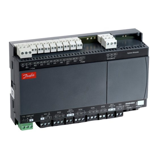
Page 62: Function Data
Relative humidity range [%] 20 – 80%, non-condensing Shocks/Vibrations No shocks and vibrations allowed Dimensions Measurements are in mm. Figure 49: AK-CC55 Multi Coil Figure 50: AK-UI55 Set Figure 51: AK-OB55 © Danfoss | Climate Solutions | 2022.08 BC365022028193en-000201 | 62... -
Page 63: Ordering
AK-CC55 Multi Coil Ordering The list contains the components that make up an AK-CC55 Multi Coil setup. For other Danfoss products mentioned in the document, such as sensors and valves, refer to relevant product documentation. Table 52: Ordering Type Symbol Function Code no. -
Page 64: Certificates, Declarations, And Approvals
Some approvals may change over time. You can check the most current status at danfoss.com or contact your local Danfoss representative if you have any questions. -
Page 65: Statements For The Ak-Ui55 Bluetooth Display
L'exploitation est autorisée aux deux conditions suivantes : (1) l'appareil ne doit pas produire de brouillage, et (2) l'utilisateur de l'appareil doit accepter tout brouillage radioélectrique subi, même si le brouillage est susceptible d'en compromettre le fonctionnement. © Danfoss | Climate Solutions | 2022.08 BC365022028193en-000201 | 65... -
Page 66: Online Support
Online support Danfoss offers a wide range of support along with our products, including digital product information, software, mobile apps, and expert guidance. See the possibilities below. The Danfoss Product Store The Danfoss Product Store is your one-stop shop for everything product related—no matter where you are in the world or what area of the cooling industry you work in.
Need help?
Do you have a question about the AK-CC55 Multi Coil and is the answer not in the manual?
Questions and answers