
Subscribe to Our Youtube Channel
Related Manuals for Danfoss AKC 25H1


Summary of Contents for Danfoss AKC 25H1
- Page 1 Function description ADAP-KOOL ® Compressor Pack Controller AKC 25H1 RC.1J.Z3.02 → RC.1J.Z4.02 09-1999...
-
Page 2: Table Of Contents
Supporting text ........................23 Installation considerations ....................23 List of literature ........................24 Validity This function description was revised in September 1999 and applies to AKC 25H1 with code numbers 084B2017 and 084B2018. Function description RC.1J.Z4.02 © Danfoss 09/1999 AKC 25H1... -
Page 3: Contents Introduction
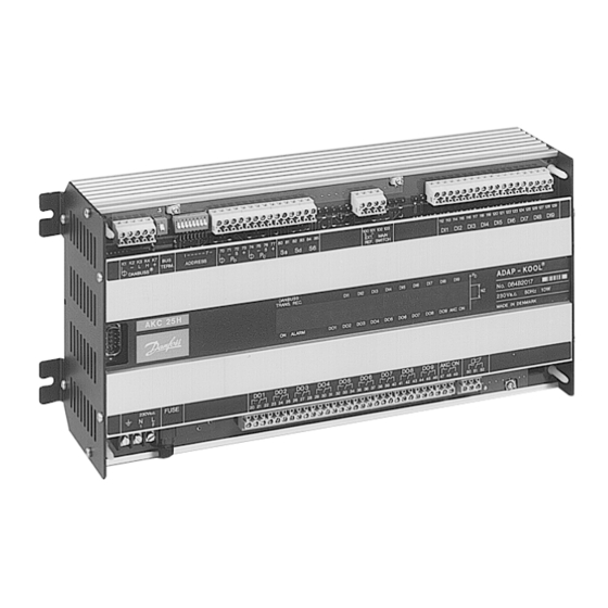
Introduction AKC 25H1 is a complete control unit for capacity regulation of compressors and condensers in commercial refrigeration. The controller can be used in combination with other controllers in the Danfoss ADAP-KOOL ® refrigeration control system. In addition to capacity regulation the controller can transmit signals to other controllers about operating conditions, e.g. -
Page 4: Operation
® System information Controller type AKC 25H1 is a unit in the ADAP-KOOL refrigeration control system. The controller can be linked up with other controllers in the system via a two-core connection - the DANBUSS Data Communication. Through this connection information can be transmitted between the units, like settings, measurements, alarms etc. -
Page 5: Capacity Regulation Of Compressor
Settings Compressor Ctrl. Forced Nght OFF/ON (This setting can also be made from a mastergateway’s override function). New reference = set reference + voltage signal x “K1 Gain K”/10 + “Night Ref.K”. AKC 25H1 Function description RC.1J.Z4.02 © Danfoss 09/1999... -
Page 6: Neutral Zone And Regulating Band
(to avoid a cutout before the suction pressure has had time to become stable). The setting ranges are from 0 to 25 minutes. Output Configuration DO Relay No. ( ) DO( ) Recy m ___ DO( ) ON m ___ Function description RC.1J.Z4.02 © Danfoss 09/1999 AKC 25H1... -
Page 7: Sequence For Cut In And Cut Out Of Capacity
“DI” input. This input is a 230 V a.c. input. (The safety circuit must stop the compressor without the help of AKC 25H1). If the safety circuit is broken, the controller will cut out all output relays for the compressor in question and give an alarm. -
Page 8: Hourmeter
Pc will trigger an alarm signal. To avoid this alarm, a signal can be picked up from pressure transmitter PO. Connect terminal 72 to 76 (“s” to “s”). The monitoring function for PCmax must be set at the highest possible value. Function description RC.1J.Z4.02 © Danfoss 09/1999 AKC 25H1... -
Page 9: Capacity Regulation Of Condenser
Cut out takes place in the opposite sequence. Thus, the last cut in step will be cut out first. Output Configuration DO Relay No. ( ) DO( ) Type 2 (2=condenser) DO( ) Dev. No AKC 25H1 Function description RC.1J.Z4.02 © Danfoss 09/1999... -
Page 10: Signal From The Condenser's Safety Controls
PO will trigger an alarm signal. To avoid this alarm, a signal may be picked up from pressure transmitter Pc. Connect terminal 72 to 76 (“s” to “s”). The monitoring function for POmin is now set at the lowest possible value. Function description RC.1J.Z4.02 © Danfoss 09/1999 AKC 25H1... -
Page 11: Overriding
The “AKC ON” relay cuts out when all compressor steps are stopped. E.g. when: - the function switch “Main Sw.” on AKC 25H1 has been put in position 0 - the “Main Switch” input is broken. - or during normal regulation when one of the monitoring functions has cut out the regulation. -
Page 12: Monitoring
Renewed cut in of compressor steps is allowed when the following conditions are complied with: - the temperature (pressure) has dropped to the 3 K below the limit value Pc Max ° C ___ Safety functions Limits with 1.Priority Function description RC.1J.Z4.02 © Danfoss 09/1999 AKC 25H1... -
Page 13: Monitoring Of Minimum Suction Pressure
The alarm will not be sounded until the time delay has expired. The time delay can be defined in the range between 0 and 60 minutes. Safety functions Limits with 1.Priority SH Max K ___ SH Min K ___ SH Delay m ___ AKC 25H1 Function description RC.1J.Z4.02 © Danfoss 09/1999... -
Page 14: Monitoring Of The Different Parts Of The Compressor's Safety Circuit
All alarm modules are double, i.e. one module can monitor two safety circuits. Each circuit is connected to a DI input on AKC 25H1. Only inputs DI1 to DI8 can be used as inputs from an alarm module. DI9 is only for monitoring of other automatic controls. -
Page 15: Supply Voltage
0-59 AKC 25H1 Adr: -- Clock: min: Note: If the controller is connected to an installation with gateway, type AKA 243/244, the gateway will reset the clock function after a power failure. AKC 25H1 Function description RC.1J.Z4.02 © Danfoss 09/1999... -
Page 16: Refrigerant
The function has been prepared for the definition of a refrigerant that differs from the above mentioned types. This definition can be made by keying the figure “13” plus a number of subsequent parameters. This setting can only be made with assistance from Danfoss. Function description RC.1J.Z4.02 © Danfoss 09/1999... -
Page 17: Service
(Main Switch = 0 or 1), “Man. ctrl.” will automatically be put in pos. OFF. At the same time the settings of the outputs will change back to the factory-set values. AKC 25H1 Function description RC.1J.Z4.02 © Danfoss 09/1999... -
Page 18: System Measurements/Data
In addition to the earlier described measurements with control panel type AKA 21 it is with operation from a PC, also possible to define the importance of the various alarms. Read the section: “Alarms and messages”. Function description RC.1J.Z4.02 © Danfoss 09/1999 AKC 25H1... -
Page 19: Alarms And Messages
RFG. type change after power up [ 1, 2, 0 ] Refrigerant type changed after the controller was started. Warning!! Change of refrigerant type can cause damage to the compressor. Cf. section on selection of refrigerant. AKC 25H1 Function description RC.1J.Z4.02 © Danfoss 09/1999... - Page 20 No DI defined for compressor [ 1, 2, 0 ] A compressor is defined but not a "DI input" to the compressor. If not wanted the importance must be set to "0". Function description RC.1J.Z4.02 © Danfoss 09/1999 AKC 25H1...
- Page 21 The error message cannot be removed from AKA 21, as long as the cause of the error has not been removed. When the cause of the error message has been removed, the error message will remain visible in AKA 21 until it is acknowledged by pushing “Enter”. AKC 25H1 Function description RC.1J.Z4.02 © Danfoss 09/1999...
- Page 22 • The system address of the final receiver of alarms and messages. Alarm output on AKC 25H1 The output will only be activated when the setting is [1] (see above). Activation takes place as long as the error is active.
-
Page 23: Access Codes
Electronic control is no substitute for normal, good engineering practice. Danfoss wil not be responsible for any goods, or plant components, damaged as a result of the above defects. It is the installer's responsibility to check the installation thoroughly, and to fit the necessary safety devices. -
Page 24: List Of Literature
Table for entry of menu settings AKC 25H5 (bypacked unit) ........RI.1J.1 Danfoss can accept no responsibility for possible errors in catalogues, brochures and other printed material. Danfoss reserves the right to alter its products without notice. This also applies to products already on order provided that such alternations can be made without subsequential changes being necessary in specifications already agreed.
Need help?
Do you have a question about the AKC 25H1 and is the answer not in the manual?
Questions and answers