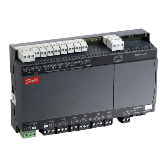
Danfoss AK-CC55 Installation Manual
Single coil
Hide thumbs
Also See for AK-CC55:
- User manual (71 pages) ,
- Installation manual (16 pages) ,
- User manual (66 pages)
Summary of Contents for Danfoss AK-CC55
- Page 1 Installation Guide AK-CC55 084R8053 Single Coil AN294432763974en-000201 Identification Dimensions 084B4082 084B4083 Principle © Danfoss | DCS (vt) | 2019.07 AN294432763974en-000201 | 1...
- Page 2 The controller is provided with labels from the factory indicating a general application. If you employ another use, labels are provided so that you can mount the relevant one. 2 | AN294432763974en-000201 © Danfoss | DCS (vt) | 2019.07...
- Page 3 © Danfoss | DCS (vt) | 2019.07 AN294432763974en-000201 | 3...
- Page 4 Custom set-up 4 | AN294432763974en-000201 © Danfoss | DCS (vt) | 2019.07...
-
Page 5: Data Communication
Refrigeration is resumed at the same time when all controllers have terminated defrost. External display AK-UI55 Display 084B4075 / 084B4076 / 084B4077 Cable 3 m: 084B4078 Cable 6 m: 084B4079 (L: Max. 100 m) RJ 12 © Danfoss | DCS (vt) | 2019.07 AN294432763974en-000201 | 5... - Page 6 See drawing on page 5. The defined function is active when the input is short-circuited or Please note: when replacing AK-CC550 with AK-CC55, S and opened, depending on the function defined in o37. ground must be switched.
-
Page 7: Supply Voltage
There is connection between terminal 13 and 14 when the liquid receivers before the compressors. function must be active. Your local Danfoss agent will be pleased to assist with further advice, etc. Defrost There is connection between terminal 15 and 16 when defrosting takes place. - Page 8 - Keep up arrow buttons depressed at the same time as you reconnect the supply voltage " " and down " " - When FAc is shown in the display, select "yes". 8 | AN294432763974en-000201 © Danfoss | DCS (vt) | 2019.07...
- Page 9 • MODBUS: Activate scan function in system unit • If another data communication card is used in the controller: - Lon RS485: Activate the function o04 - Ethernet: Use the MAC address © Danfoss | DCS (vt) | 2019.07 AN294432763974en-000201 | 9...
-
Page 10: Menu Survey
W: This setting can be performed with password no. _ or higher (3 is the highest level). *) Always required that the regulating is stopped, r12=0) **) Always required that the regulating is stopped and set to manual service, r12= -1) 10 | AN294432763974en-000201 © Danfoss | DCS (vt) | 2019.07... - Page 11 2= Only at thermostat cut-outs during night operation Cycle time for fan pulsation (on-time + off-time) 1 min. 30 min. On-time in % of cycle time 100 % © Danfoss | DCS (vt) | 2019.07 AN294432763974en-000201 | 11...
- Page 12 100 % (100%=S4, 0%=S3) Pressure transmitter working range – min. value 1-3* o20 -1 bar 5 bar Pressure transmitter working range – max. value 1-3* o21 6 bar 200 bar 12 | AN294432763974en-000201 © Danfoss | DCS (vt) | 2019.07...
- Page 13 Time delay from "open door” refrigeration is started 0 min. 240 min. Fan operation at stopped cooling (forced closing): 0= Stopped (defrost allowed) 1= Running (defrost allowed) 2= Stopped (defrost not allowed) 3= Running (defrost not allowed) © Danfoss | DCS (vt) | 2019.07 AN294432763974en-000201 | 13...
- Page 14 Manual control of output: Compressor 2 1-2** q19 0/Off 1/On 0/Off Manual control of output: Hot gas valve 1-2** q20 0/Off 1/On 0/Off Manual control of output: Night blinds 1-2** q21 0/Off 1/On 0/Off 14 | AN294432763974en-000201 © Danfoss | DCS (vt) | 2019.07...
- Page 15 Readout of the actual rail heat effect via relay 1: Thermostat 1 operating, 2: Thermostat 2 operating Status on high voltage input DI3 Readout of thermostat's actual cut-in value Readout of thermostat's actual cut-out value © Danfoss | DCS (vt) | 2019.07 AN294432763974en-000201 | 15...
- Page 16 - Keep up " " and down " " buttons depressed at the same time as you reconnect the supply voltage - When FAc is shown in the display, select "yes". 16 | AN294432763974en-000201 © Danfoss | DCS (vt) | 2019.07...
-
Page 17: Fault Message
Missing signal from the humidity meter Data communication The importance of individual alarms can be defined with a setting. The setting must be carried out in the group "Alarm destinations" © Danfoss | DCS (vt) | 2019.07 AN294432763974en-000201 | 17... -
Page 18: Operating Status
The regulation will continue with a registered average cut-in frequency. There are two registered values – one for day operation and one for night operation. Additional information: User Guide: RS8KG102 © Danfoss | DCS (vt) | 2019.07 AN294432763974en-000201 | 18...


Need help?
Do you have a question about the AK-CC55 and is the answer not in the manual?
Questions and answers