Danfoss AK-CC55 Compact User Manual
Case/room controller (eev)
Hide thumbs
Also See for AK-CC55 Compact:
- User manual (71 pages) ,
- Installation manual (18 pages) ,
- User manual (67 pages)

Subscribe to Our Youtube Channel
Related Manuals for Danfoss AK-CC55 Compact


Summary of Contents for Danfoss AK-CC55 Compact
- Page 1 User Guide Case/room controller (EEV) Type AK-CC55 Compact SW Ver. 2.1x For refrigeration appliances and cold storage rooms.
-
Page 2: Table Of Contents
Simple hot gas defrosting Natural defrost Start of defrost Stop of defrost Defrost sequence Real-time clock Coordinated defrost Melt function Control of two compressors (only with custom set-up) Rail heat Light function © Danfoss | Climate Solutions | 2022.08 BC365212986197en-000201 | 2... - Page 3 Heating function (only with custom set-up) Digital inputs Forced closing Door contact Display Override Applications AK-CC55 Compact connections and application options Application set-ups and IO connections Product identification AK-CC55 Compact connections Data communication AKV info External solid state relay for rail heat...
- Page 4 Technical data Electrical specifications Sensor and measuring data Input and output relay specifications Function data Environmental conditions Dimensions Ordering Certificates, declarations, and approvals Statements for the AK-UI55 Bluetooth display Online support © Danfoss | Climate Solutions | 2022.08 BC365212986197en-000201 | 4...
-
Page 5: Introduction
In addition to the output of the electronic AKV injection valve, the controller has relay outputs which are defined by the application setting Figure 1: AK-CC55 with evaporator, AKV valve and sensor positions © Danfoss | Climate Solutions | 2022.08 BC365212986197en-000201 | 5... -
Page 6: Portfolio Overview
Heating function Control of air humidity Adaptive superheat Adaptive liquid control (zero superheat control for transcritical CO systems with liquid ejectors) Adaptive defrosting Product sensor Oil recovery RS485 Lon, option (AK-OB55) © Danfoss | Climate Solutions | 2022.08 BC365212986197en-000201 | 6... -
Page 7: Connectivity
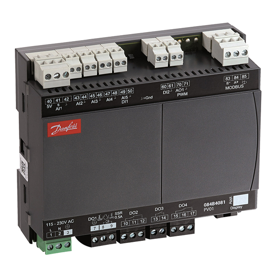
Regulation is performed using a TXV in combination with a liquid line solenoid valve, controlling a compressor or an AKV expansion valve. AK-CC55 Compact is without display, and can be extended with one external display (see Figure 3 Figure Figure 3: AK-CC55 Compact Figure 4: AK-CC55 Compact with external display. - Page 8 AK-CC55 Compact Figure 5: AK-UI55 Info Figure 6: AK-UI55 Set Figure 7: AK-UI55 Bluetooth © Danfoss | Climate Solutions | 2022.08 BC365212986197en-000201 | 8...
-
Page 9: Controller Functionality
When adaptive liquid control is initiated, the superheat of the evaporator will be minimized so that a controlled amount of liquid is present at the outlet of the evaporator. © Danfoss | Climate Solutions | 2022.08 BC365212986197en-000201 | 9... -
Page 10: Thermostatic Expansion Valve Control
Accidental actuation may allow liquid throughput to the compressor. It is the installer’s responsibility to ensure that signal loss to the controller will not result in liquid throughput to the compressor. Danfoss accepts no responsibility for damage resulting from inadequate installation. -
Page 11: Temperature Control
For the defrost control, separate defrost stop temperature and max. defrost time can be set for each thermostat band. For the compressor control it is possible to disable the second compressor in thermostat band 2 if required. Figure 11: Thermostat band function with two different band settings © Danfoss | Climate Solutions | 2022.08 BC365212986197en-000201 | 11... -
Page 12: Night Setback Of Thermostat Value
For the S3, S4 and S5 sensors, the user can select between the following sensor types: 0 = Pt1000 (Danfoss AKS 11) 1 = PTC1000 (Danfoss EKS 111) 2 = NTC 5k (Danfoss EKS 211) 3 = NTC 10k (Danfoss EKS 221) 4 = User-defined If “User-defined”... -
Page 13: Appliance Cleaning
A user defined temperature sensor can only be be defined within the temperature range from -40 – +60 °C and within the resistance range from 400 – 179.999 ohm. When applying a new user defined sensor type, please contact Danfoss for validation of compliance and measuring accuracy. -
Page 14: Defrost
Here defrost can be started at fixed times of the day and night. However, max. 6 defrosts per day. Contact: Defrost is started with a contact signal on a digital input. © Danfoss | Climate Solutions | 2022.08 BC365212986197en-000201 | 14... -
Page 15: Stop Of Defrost
Drain delay (Hot gas only): where the drain valve is opened to drain the liquid refrigerant Fan delay: where the fans are restarted when the remaining water on the evaporator has turned into ice © Danfoss | Climate Solutions | 2022.08 BC365212986197en-000201 | 15... -
Page 16: Real-Time Clock
The controller has a built-in real-time clock which can be used to start defrosts. This clock has a power reserve of four days. If the controller is equipped with data communication, the clock will automatically be updated from a Danfoss system manager. -
Page 17: Melt Function
The compressor's settings for ”Min. On time” and ”Min. Off time” will always have top priority during normal regulation. But if one of the override functions is activated, like e.g. defrost, door open function, case shutdown, forced closing, the ”Min. On time” will be disregarded. © Danfoss | Climate Solutions | 2022.08 BC365212986197en-000201 | 17... -
Page 18: Rail Heat
At a dewpoint which is equal to or lower than the value in 086, the effect will be the value indicated in o88. In the area between the two dewpoint values, the controller will manage the power to be supplied to the rail heat. © Danfoss | Climate Solutions | 2022.08 BC365212986197en-000201 | 18... -
Page 19: Fan
If the Fan output is activated, then the fan is running with 100% speed. If the Fan ECO output is also activated, then the fan is running with reduced speed (typically 50%). If both fan outputs are de-activated, then the fans are stopped. © Danfoss | Climate Solutions | 2022.08 BC365212986197en-000201 | 19... -
Page 20: Light Function
A setting can define that the night blind is opened when "r12" (Main switch) is set to off (see o98). When the night blind rolls down, the fan will be stopped for the set time. The night blind can thereby roll down to the correct position. © Danfoss | Climate Solutions | 2022.08 BC365212986197en-000201 | 20... -
Page 21: Heating Function (Only With Custom Set-Up)
Example: If DI1 is to be used to start a defrost, o02 must be set to 4. Forced closing The AKV valves can be closed with an external signal ("Forced closing"). © Danfoss | Climate Solutions | 2022.08 BC365212986197en-000201 | 21... -
Page 22: Door Contact
MC Max. Te offset Requested offset to actual evaporating temperature in order to keep the air temperature at the actual setpoint MC Liquid control Master control signal allowing switch to adaptive liquid control © Danfoss | Climate Solutions | 2022.08 BC365212986197en-000201 | 22... - Page 23 Master control signal that will lock down all Bluetooth data communication MC Min. delta T Required minimum delta temperature across evaporator (S3 - Te) in order to keep the air temperature at the actual setpoint © Danfoss | Climate Solutions | 2022.08 BC365212986197en-000201 | 23...
-
Page 24: Applications
S₃ S₅ S₂ S₅ S₃ Figure 27: Cold room configuration with door, light and heat control function AK-CC55 Compact connections and application options Figure 28: Electrical connections AK-CC55 Compact 40 41 42 43 44 45 46 47 48 49 50... -
Page 25: Application Set-Ups And Io Connections
AK-CC55 Compact AK-CC55 Compact is optimised for control of one evaporator plus different combinations of light, rail heat and alarm relays. It has 4 Digital Outputs (DO), known as DO1 – DO4, one Analogue Output (AO), known as AO1, 4 Analogue Inputs (AI), known as AI1 –... - Page 26 43 44 45 46 47 48 49 50 60 61 70 71 83 84 MODBUS 115 – 230 V AC Comp. Railheat Defrost 10 11 12 13 14 15 16 17 © Danfoss | Climate Solutions | 2022.08 BC365212986197en-000201 | 26...
- Page 27 43 44 45 46 47 48 49 50 60 61 70 71 83 84 MODBUS 115 – 230 V AC Alarm Defrost 10 11 12 13 14 15 16 17 © Danfoss | Climate Solutions | 2022.08 BC365212986197en-000201 | 27...
-
Page 28: Product Identification
The application number is indicated on the left-hand side of the labels. Use the label fitting the selected application. © Danfoss | Climate Solutions | 2022.08 BC365212986197en-000201 | 28... -
Page 29: Ak-Cc55 Compact Connections
It is important that the installation of the data communication cable is performed correctly with sufficient distance to high voltage cables. AKV info Figure 40: AKV info 230 V AC (115 AC) 230 V or 115 V AC coil Max. 0.5 A Not overload protected © Danfoss | Climate Solutions | 2022.08 BC365212986197en-000201 | 29... -
Page 30: External Solid State Relay For Rail Heat
Figure 43: Coordinated defrost via cable connections Max. 10 The following controllers can be connected in this way: EKC 204A, AK-CC 210, AK-CC 250, AK-CC 450, AK-CC 550 and AK-CC55. © Danfoss | Climate Solutions | 2022.08 BC365212986197en-000201 | 30... -
Page 31: External Display Ak-Ui55
There is connection between terminal 15 and 16 when defrosting takes place. DO2-DO4 + AO1 and Here, the different outputs can be custom defined in q02-q09 Application 4 / 9 © Danfoss | Climate Solutions | 2022.08 BC365212986197en-000201 | 31... - Page 32 Electronic controls are no substitute for normal, good engineering practice. Danfoss will not be responsible for any goods, or plant components, damaged as a result of the above defects. It is the installer's responsibility to check the installation thoroughly, and to fit the necessary safety devices.
-
Page 33: Operation
The display keys will be locked and unlocked by means of a master control signal from the System Manager. © Danfoss | Climate Solutions | 2022.08 BC365212986197en-000201 | 33... - Page 34 • When FAc is shown in the display, select "yes" NOTE: The OEM factory setting will either be the Danfoss factory settings or a user defined factory setting if one has been made. The user can save his setting as OEM factory setting via parameter o67.
-
Page 35: Parameter Groups When Operating Via Display
Application set-ups and IO connections) Open parameter o61 and set the application number For network. Set the address in o03 Then select a set of presets from the "Food type" help table © Danfoss | Climate Solutions | 2022.08 BC365212986197en-000201 | 35... - Page 36 Upper alarm limit for S6 (A22) 14 °C 8 °C 8 °C -15 °C -15 °C Lower alarm limit for S6 (A23) 0 °C -5 °C -5 °C -30 °C -30 °C © Danfoss | Climate Solutions | 2022.08 BC365212986197en-000201 | 36...
-
Page 37: Ak-Ui55 Display Menu (Sw Ver. 2.1X)
Low alarm limit 1 -60.0 °C 50.0 °C -30.0 °C High alarm limit 2 -60.0 °C 50.0 °C 8.0 °C Low alarm limit 2 -60.0 °C 50.0 °C -30.0 °C © Danfoss | Climate Solutions | 2022.08 BC365212986197en-000201 | 37... -
Page 38: Compressor
In order to change this parameter the regulation must be stopped via the parameter r12 Main switch = OFF. In order to change this parameter the regulation must be stopped via the parameter r12 Main switch = OFF. © Danfoss | Climate Solutions | 2022.08 BC365212986197en-000201 | 38... -
Page 39: Fan Control
8=Alarm at closed, 9=Alarm at open, 10=Case cleaning, 11=Forced cool- ing, 12=Open blinds, 14=Forced closing, 15=Shutdown, 16=Light control, 20=Leak detec- tion, 21=Adaptive liquid control, 29=Door fan stop Network address © Danfoss | Climate Solutions | 2022.08 BC365212986197en-000201 | 39... - Page 40 Custom, 5=5. EEV/ Comp/Fan/Defrost, 6=6. EEV/Alarm/Fan/Defrost, 7=7. EEV/Light/Fan/ Defrost, 8=8. EEV/ Rail/Fan/Defrost, 9=9. EEV/Custom Access code 2 Make new factory 0=OFF, 1=ON Rail heat control mode 0=ON, 1=Day/Night timer, 2=Dew point ctrl. © Danfoss | Climate Solutions | 2022.08 BC365212986197en-000201 | 40...
-
Page 41: Control
Rail heat - override 0=MAN OFF, 1=MAN ON Alarm relay - override 0=MAN OFF, 1=MAN ON Light - override 0=MAN OFF, 1=MAN ON Compressor 2 - override 0=MAN OFF, 1=MAN ON © Danfoss | Climate Solutions | 2022.08 BC365212986197en-000201 | 41... -
Page 42: Service
S2 Gas outlet A -200.0 °C 200.0 °C 0.0 °C Superheat A -200.0 °C 200.0 °C 0.0 °C Superheat reference A -200.0 °C 200.0 °C 0.0 °C EEV opening A 100 % © Danfoss | Climate Solutions | 2022.08 BC365212986197en-000201 | 42... - Page 43 0=OFF, 1=ON Network status 100 % Rail heat PWM 100 % Food temperature A -200.0 °C 200.0 °C 0.0 °C Defrost sensor tempera- -200.0 °C 200.0 °C 0.0 °C ture A © Danfoss | Climate Solutions | 2022.08 BC365212986197en-000201 | 43...
-
Page 44: Operation Via Ak-Ui55 Bluetooth
• The operation is locked and cannot be operated via Bluetooth. • Unlock from the system manager. Figure 49: Connect to controller Figure 50: Controller dashboard Figure 51: Set-up menu The functions are described on Page 45 – Page © Danfoss | Climate Solutions | 2022.08 BC365212986197en-000201 | 44... -
Page 45: Ak-Cc55 Connect Menu (Sw Ver. 2.1X)
Refrigerant ant is not part of the list, the user defined option can 14=R32, 11=R114, 3=R134a, 12=R142b, 24=R170, be used. Please contact Danfoss for detailed informa- 15=R227, 25=R290, 16=R401A, 18=R402A, 19=R404A, tionWarning: Wrong selection of refrigerant may 21=R407A, 22=R407B, 20=R407C, 37=R407F, cause damage to the system. -
Page 46: Thermostat Control
Thermostat temperature u17 Ther. air temp. A Food temperature A Read out of food temperature U72 Food temp. S3 Air ON evap. A Actual sensor value u12 S3 air temp. © Danfoss | Climate Solutions | 2022.08 BC365212986197en-000201 | 46... - Page 47 S4 temperature has risen 2K above the set limit Air heater neutral Heat function. Set the width of the Neutral Zone for r62 Heat NZ zone changeover from cooling to heating " © Danfoss | Climate Solutions | 2022.08 BC365212986197en-000201 | 47...
-
Page 48: Alarm Limits And Delays
Alarm delay DI 1 Time delay for digital input alarm A27 Al.Delay DI1 Alarm delay DI 2 Time delay for digital input alarm A28 Al.Delay DI2 © Danfoss | Climate Solutions | 2022.08 BC365212986197en-000201 | 48... -
Page 49: Injection Control
Period time for the pulse width modulation n63 Pwm Period time Brine valve max OD Expert setting - please contact Danfoss for further in- n64 Pwm Max. OD Brine valve min OD Expert setting - please contact Danfoss for further in- n65 Pwm Min. - Page 50 If this signal fails to appear for one reason or another, the controller will itself start the refrigeration when this standby time has elapsed. © Danfoss | Climate Solutions | 2022.08 BC365212986197en-000201 | 50...
-
Page 51: Defrost Schedules
Compressor 2 Actual status of output function 0=OFF, 1=ON u67 Comp2 relay Min ON time Minimum time the compressor is to run once it has c01 Min. On time been started. © Danfoss | Climate Solutions | 2022.08 BC365212986197en-000201 | 51... -
Page 52: Fan Control
0=OFF, 1=ON u61 Railh. relay Railheat power Readout of the actual rail power in % u85 Rail DutyC % Rail heat PWM Actual status of output function U59 Railheat PWM © Danfoss | Climate Solutions | 2022.08 BC365212986197en-000201 | 52... -
Page 53: Light/Blinds/Cleaning Control
All other outputs are Off. 2 = Cleaning with stopped fans. All outputs are Off. If the function is controlled by a digital input signal, the relevant sta- tus can be seen here in the menu. © Danfoss | Climate Solutions | 2022.08 BC365212986197en-000201 | 53... -
Page 54: Display Control
Defrost Prio alarm group. Be aware - by selecting "Disable" the alarms will not be shown on the display or be routed to the alarm relay or to the network. © Danfoss | Climate Solutions | 2022.08 BC365212986197en-000201 | 54... -
Page 55: Miscellaneous
Superheat close A Minimum superheat limit where the valve is closing --- SH close AFidentForce A Expert setting - contact Danfoss for further informa- --- AFidentForce tion Superheat Kp min A Min limit for amplification factor of PI controller ad-... - Page 56 Injection duty cycle Expert setting - contact Danfoss for further informa- --- ThDutyCycle tion Injection duty cycle Expert injection setting - contact Danfoss for further --- ActDutyCycle information P-gain Expert injection setting - contact Danfoss for further --- P - Gain information OD Ctrl.
-
Page 57: Fault Message
Inputs and outputs have not been configured correctly NOTE: Data communication The importance of individual alarms can be defined with a setting. The setting must be carried out in the group "Alarm destinations" © Danfoss | Climate Solutions | 2022.08 BC365212986197en-000201 | 57... -
Page 58: Operating Status
• If S3 or S4 sensor fails, the thermostat will operate with a registered ON/OFF duty cycle during day and night operation. • If S3 or S4 sensor fails, the thermostat will operate with a registered ON/OFF duty cycle during day and night operation. © Danfoss | Climate Solutions | 2022.08 BC365212986197en-000201 | 58... -
Page 59: Product Specification
• DO2 / DO3 is recommended for load with high inrush current e.g. EC Fan and LED light. • All relays are sealed for use with flammable refrigerant like Propane R290. • Compliance with EN 60 335-2-89: 2010 Annex BB. © Danfoss | Climate Solutions | 2022.08 BC365212986197en-000201 | 59... -
Page 60: Function Data
Enclosure rating IP IP20 Relative humidity range [%] 20 – 80%, non-condensing Shocks/Vibrations No shocks and vibrations allowed Dimensions Measurements are in mm. Figure 52: AK-CC55 Compact Figure 53: AK-CC55 Set © Danfoss | Climate Solutions | 2022.08 BC365212986197en-000201 | 60... -
Page 61: Ordering
AK-CC55 Compact Ordering The list contains the components that make up an AK-CC55 Compact setup. For other Danfoss products mentioned in the document, such as sensors and valves, refer to relevant product documentation. Table 49: Ordering Type Symbol Function Code no. -
Page 62: Certificates, Declarations, And Approvals
Some approvals may change over time. You can check the most current status at danfoss.com or contact your local Danfoss representative if you have any questions. -
Page 63: Statements For The Ak-Ui55 Bluetooth Display
L'exploitation est autorisée aux deux conditions suivantes : (1) l'appareil ne doit pas produire de brouillage, et (2) l'utilisateur de l'appareil doit accepter tout brouillage radioélectrique subi, même si le brouillage est susceptible d'en compromettre le fonctionnement. © Danfoss | Climate Solutions | 2022.08 BC365212986197en-000201 | 63... -
Page 64: Online Support
Online support Danfoss offers a wide range of support along with our products, including digital product information, software, mobile apps, and expert guidance. See the possibilities below. The Danfoss Product Store The Danfoss Product Store is your one-stop shop for everything product related—no matter where you are in the world or what area of the cooling industry you work in.
Need help?
Do you have a question about the AK-CC55 Compact and is the answer not in the manual?
Questions and answers