Sign In
Upload
Download
Table of Contents
Contents
Add to my manuals
Delete from my manuals
Share
URL of this page:
HTML Link:
Bookmark this page
Add
Manual will be automatically added to "My Manuals"
Print this page
×
Bookmark added
×
Added to my manuals
Manuals
Brands
Danfoss Manuals
Controller
AK-CC 750 series
Manual
Danfoss AK-CC 750 series Manual
Controller for evaporator control
Hide thumbs
1
2
3
4
5
6
7
8
9
10
11
12
13
14
15
16
17
18
19
20
21
22
23
24
25
26
27
28
29
30
31
32
33
34
35
36
37
38
39
40
41
42
43
44
45
46
47
48
49
50
51
52
53
54
55
56
57
58
59
60
61
62
63
64
65
66
67
68
69
70
71
72
73
74
75
76
77
78
79
80
81
82
83
84
85
86
87
88
89
90
91
92
93
94
95
96
Table Of Contents
97
page
of
97
Go
/
97
Contents
Table of Contents
Bookmarks
Table of Contents
Introduction
Principles
Design of a Controller
Module Survey
Common Data for Modules
Controller
Extension Module AK-XM 101A
Extension Module AK-XM 102A / AK-XM 102B
Extension Module AK-XM 204A / AK-XM 204B
Extension Module AK-XM 205A / AK-XM 205B
Extension Module AK-OB 101A
Display Module EKA 163B / EKA 164B
Transformer Module AK-PS 075 / 150
Case Power Module
Preface to Design
Connections
Design of a Evaporator Control
Connections
Planning Table
Length
Determine the Connection Points
Connection Diagram
Supply Voltage
Ordering
Mounting and Wiring
Mounting
Wiring
Configuration and Operation
Configuration
Authorization
Unlock the Configuration of the Controllers
System Setup
Set Plant Type
Definition of Thermostat
Definition of Sections
Definition of Defrost Functions
Definition of Common Functions
Configuration of Inputs and Outputs
Set Alarm Priorities
Lock Configuration
Check Configuration
Check of Connections
Check of Settings
Installation in Network
First Start of Control
Start the Control
Setup Logs
Manual Defrost
Regulating Functions
Introduction
Thermostat Function
Temperature Alarms
Common Functions
Liquid Injection
Defrost
Miscellaneous
Information
Alarm Texts
Appendix - Recommended Connection
Advertisement
Quick Links
1
Introduction
2
Display Module Eka 163B / Eka 164B
3
Configuration and Operation
4
Alarm Texts
Download this manual
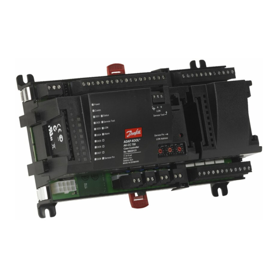
Controller for evaporator control
AK-CC 750 - 080Z0130 & 080Z0139
Manual
Table of
Contents
Previous
Page
Next
Page
1
2
3
4
5
Advertisement
Table of Contents
Need help?
Do you have a question about the AK-CC 750 series and is the answer not in the manual?
Ask a question
Questions and answers
Related Manuals for Danfoss AK-CC 750 series
Industrial Electrical Danfoss AK-CC 750 User Manual
(10 pages)
Controller Danfoss AK-CC 450 User Manual
Controller for appliance control (37 pages)
Controller Danfoss AK-CH 650 User Manual
Capacity controller for water chillers (114 pages)
Controller Danfoss AK-CH 650 Service Manual
Capacity controller for water chiller (15 pages)
Controller Danfoss AK-CC 550 Instructions Manual
084b8020;084b8021 (12 pages)
Controller Danfoss AK-CC 550 Manual
Controller for appliance control (36 pages)
Controller danfoss AKC 25H1 Description
Compressor pack controller for adap-kool (24 pages)
Controller Danfoss AK-CC 460 Instructions Manual
(9 pages)
Controller Danfoss AK-CC55 User Manual
Controller for appliance control (71 pages)
Controller Danfoss AK-CC55 User Manual
Case/room controller (eev) (69 pages)
Controller Danfoss AK-CC55 Compact Installation Manual
(16 pages)
Controller Danfoss AK-CC55 Compact User Manual
Case/room controller (eev) (64 pages)
Controller Danfoss AK-CC55 Multi Coil User Manual
Case/room controller (eev) (66 pages)
Controller Danfoss AK-CC55 Water Loop User Manual
Case controller for semi plug-in (67 pages)
Controller Danfoss AK-CS On Board Manual
(24 pages)
Controller Danfoss AKC 151R Instructions Manual
(9 pages)
This manual is also suitable for:
080z0139
080z0130
Ak-cc 750
Table of Contents
Save PDF
Print
Rename the bookmark
Delete bookmark?
Delete from my manuals?
Login
Sign In
OR
Sign in with Facebook
Sign in with Google
Upload manual
Upload from disk
Upload from URL


Need help?
Do you have a question about the AK-CC 750 series and is the answer not in the manual?
Questions and answers