Danfoss AK-CC55 Water Loop User Manual
Case controller for semi plug-in
Hide thumbs
Also See for AK-CC55 Water Loop:
- User manual (71 pages) ,
- Installation manual (18 pages) ,
- User manual (66 pages)

Related Manuals for Danfoss AK-CC55 Water Loop


Summary of Contents for Danfoss AK-CC55 Water Loop
- Page 1 User Guide Case controller for semi plug-in Type AK-CC55 Water Loop SW Ver. 1.2x For refrigeration appliances and cold storage rooms.
-
Page 2: Table Of Contents
Start of defrost Stop of defrost Defrost sequence Real-time clock Coordinated defrost Melt function Rail heat Light function Night blind (only with custom set-up) Heating function (only with custom set-up) Digital inputs © Danfoss | Climate Solutions | 2022.04 BC378540472015en-000101 | 2... - Page 3 AK-CC55 Water Loop Door contact Display Override Applications AK-CC55 Water Loop connections and application options Wiring diagram Wiring Special wiring details Data communication External solid state relay for rail heat Coordinated defrost via cable connections External display AK-UI55 Operation Operation via data communication...
- Page 4 Technical data Electrical specifications Sensor and measuring data Input and output relay specifications Function data Environmental conditions Dimensions Ordering Certificates, declarations, and approvals Statements for the AK-UI55 Bluetooth display Online support © Danfoss | Climate Solutions | 2022.04 BC378540472015en-000101 | 4...
-
Page 5: Introduction
Application coverage The AK-CC55 Water Loop controller has a broad application coverage and supports the following main applications: Figure 1: Application 1,2,5 and 6 Single compressor application with either on/off or variable speed control of the compressor. - Page 6 Figure 2: Application 3 and 4 Dual compressor application with either sequential or cyclic on/off control of the two compressor circuits. Figure 3: Application 7 and 8 Variable speed control of a feeding brine pump. © Danfoss | Climate Solutions | 2022.04 BC378540472015en-000101 | 6...
-
Page 7: Connectivity
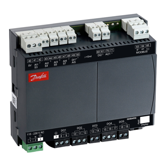
Temperature control is performed by on/off control of a single or dual compressor, variable speed control of a compressor or a brine pump. AK-CC55 Water Loop is without display, and can be extended with one external display (see Figure 5 Figure Figure 5: AK-CC55 Water Loop Figure 6: AK-CC55 Water Loop with external display. - Page 8 AK-CC55 Water Loop Figure 7: AK-UI55 Info Figure 8: AK-UI55 Set Figure 9: AK-UI55 Bluetooth © Danfoss | Climate Solutions | 2022.04 BC378540472015en-000101 | 8...
-
Page 9: Controller Functionality
As an ordinary ON/OFF regulation with a differential, or As a modulating control where the temperature variation will not be nearly as high as in ON/OFF control. Figure 10: Control methods © Danfoss | Climate Solutions | 2022.04 BC378540472015en-000101 | 9... -
Page 10: Temperature Monitoring
For the S3, S4, S5, S7 and S8 sensors, the user can select between the following sensor types: 0 = Pt1000 (Danfoss AKS 11) 1 = PTC1000 (Danfoss EKS 111) 2 = NTC 5k (Danfoss EKS 211) 3 = NTC 10k (Danfoss EKS 221) 4 = User-defined ©... -
Page 11: Compressor And Pump Control
A user defined temperature sensor can only be be defined within the temperature range from -40 – +60 °C and within the resistance range from 400 – 179.999 ohm. When applying a new user defined sensor type, please contact Danfoss for validation of compliance and measuring accuracy. - Page 12 To eliminate overshoot/undershoot at high load changes, the rate of change in speed can be limited via a max. slope setting, which defines the maximum allowed change in speed per second (%/s). © Danfoss | Climate Solutions | 2022.04 BC378540472015en-000101 | 12...
-
Page 13: Voltage Signal
AO1 signal type = voltage o28 AO1 max. voltage = 10 V o27 AO1 min. voltage = 0 V c46 min. speed = 20% c47 start speed = 45% c48 max. speed = 100% © Danfoss | Climate Solutions | 2022.04 BC378540472015en-000101 | 13... -
Page 14: Frequency Signal
100% equal to 0% capacity and the pump will be cut-out via the relay signal. Oil return management If the variable speed compressor is running with a low speed for a long period, there is a risk that oil will be trapped © Danfoss | Climate Solutions | 2022.04 BC378540472015en-000101 | 14... - Page 15 Resonance elimination Speed control can cause mechanical resonance vibrations to occur in the system and thereby create irritating noise. To prevent this, AK-CC55 Water Loop features an option of eliminating the speed range where the mechanical vibrations are present. The speed resonance range is defined as a minimum resonance limit and a resonance zone. Within the defined resonance range, the speed will be kept constant - please refer to the curve below.
-
Page 16: Condenser Monitoring And Control
For single step compressor, only the alarm will be generated as the compressor capacity cannot be reduced, without full loss of cooling. The high S7 temperature monitoring is not enabled for the brine pump applications as there is no condenser present. © Danfoss | Climate Solutions | 2022.04 BC378540472015en-000101 | 16... - Page 17 Furthermore, a condenser fan override function can be defined for one of the digital inputs, so that the air-cooled condenser can be used to provide heat to the store if needed. © Danfoss | Climate Solutions | 2022.04 BC378540472015en-000101 | 17...
-
Page 18: Appliance Cleaning
“Main switch”, but this happens without an “A45 standby alarm”. The function can be enabled by a switch on the DI input or via a setting through data communication. Defrost control Defrost method The following defrost methods can be selected: 0: None © Danfoss | Climate Solutions | 2022.04 BC378540472015en-000101 | 18... -
Page 19: Electrical Defrosting
Here defrost can be started at fixed times of the day and night. However, max. 6 defrosts per day. Contact: Defrost is started with a contact signal on a digital input. © Danfoss | Climate Solutions | 2022.04 BC378540472015en-000101 | 19... -
Page 20: Stop Of Defrost
Drip off, where remaining water is dripping off evaporator Fan delay, where the fans are restarted when the remaining water on the evaporator has turned into ice Figure 30: Electrical defrost Time Defrost Hold Drip Fan delay © Danfoss | Climate Solutions | 2022.04 BC378540472015en-000101 | 20... -
Page 21: Real-Time Clock
The controller has a built-in real-time clock which can be used to start defrosts. This clock has a power reserve of four days. If the controller is equipped with data communication, the clock will automatically be updated from a Danfoss system manager. -
Page 22: Melt Function
At a dewpoint which is equal to or lower than the value in o86, the effect will be the value indicated in o88. In the area between the two dewpoint values, the controller will manage the power to be supplied to the rail heat. © Danfoss | Climate Solutions | 2022.04 BC378540472015en-000101 | 22... -
Page 23: Fan
If the Fan output is activated, then the fan is running with 100% speed. If the Fan ECO output also is activated, then the fan is running with reduced speed (typically 50%). If both fan outputs are de-activated, then the fans are stopped. © Danfoss | Climate Solutions | 2022.04 BC378540472015en-000101 | 23... -
Page 24: Light Function
When the night blind function is used, the thermostat function can control with different weighting between the S3 and S4 sensors. A weighting during day operation and another when the blind is closed. © Danfoss | Climate Solutions | 2022.04 BC378540472015en-000101 | 24... -
Page 25: Heating Function (Only With Custom Set-Up)
Door alarm Defrost start Main switch Night setback Thermostat band Alarm at closed Alarm at open Case cleaning Forced cooling Open blinds Coordinated defrost Shutdown Light control Leak detection Compressor safety © Danfoss | Climate Solutions | 2022.04 BC378540472015en-000101 | 25... -
Page 26: Door Contact
Master control signal that will provide forced cooling MC Defrost start Master control signal for starting a defrost. At adaptive defrost the defrost might be skipped if the defrost is not needed © Danfoss | Climate Solutions | 2022.04 BC378540472015en-000101 | 26... - Page 27 Master control signal that will lock down all Bluetooth data communication and optionally also lock the display keyboard (parame- MC Key/Bluetooth lock ter P89) MC Force cond. fan Mater control signal for starting condenser fan in plug-in cabinets in order to reclaim heat in the store © Danfoss | Climate Solutions | 2022.04 BC378540472015en-000101 | 27...
-
Page 28: Applications
AK-CC55 Water Loop Applications AK-CC55 Water Loop is designed for control of semi plug-in units with a water/brine cooled condenser. The following semi plug-in unit applications are selected via a single application mode setting. Figure 39: Application 1+2 – Single circuit/compressor Figure 40: Application 3+4 –... -
Page 29: Ak-Cc55 Water Loop Connections And Application Options
AK-CC55 Water Loop Figure 42: Application 7+8 – Variable speed brine pump AK-CC55 Water Loop connections and application options Figure 43: Electrical connections AK-CC55 Water Loop 40 41 42 43 44 45 46 47 48 49 50 60 61 70 71... -
Page 30: Wiring Diagram
43 44 45 46 47 48 49 50 60 61 70 71 83 84 MODBUS 115 – 230 V AC Comp. 10 11 12 13 14 15 16 17 18 19 User defined © Danfoss | Climate Solutions | 2022.04 BC378540472015en-000101 | 30... - Page 31 43 44 45 46 47 48 49 50 60 61 70 71 83 84 MODBUS 115 – 230 V AC Comp. Alarm Light Defrost 10 11 12 13 14 15 16 17 18 19 © Danfoss | Climate Solutions | 2022.04 BC378540472015en-000101 | 31...
- Page 32 43 44 45 46 47 48 49 50 60 61 70 71 83 84 MODBUS 115 – 230 V AC Pump 10 11 12 13 14 15 16 17 18 19 User defined © Danfoss | Climate Solutions | 2022.04 BC378540472015en-000101 | 32...
-
Page 33: Wiring
Every possible safeguard is incorporated into our products to prevent this. However, a wrong installation could still present problems. Electronic controls are no substitute for normal, good engineering practice. © Danfoss | Climate Solutions | 2022.04 BC378540472015en-000101 | 33... -
Page 34: Special Wiring Details
AK-CC55 Water Loop Danfoss will not be responsible for any goods, or plant components, damaged as a result of the above defects. It is the installer's responsibility to check the installation thoroughly, and to fit the necessary safety devices. Special reference is made to the necessity of signals to the controller when the compressor is stopped and to the need of liquid receivers before the compressors. -
Page 35: External Display Ak-Ui55
AK-CC55 Water Loop Refrigeration is resumed at the same time when all controllers have terminated defrost. External display AK-UI55 Figure 55: External display AK-UI55 (Total length: max. 100 m) © Danfoss | Climate Solutions | 2022.04 BC378540472015en-000101 | 35... -
Page 36: Operation
The display keys will be locked and unlocked by means of a master control signal from the System Manager. Figure 56: Operating via AK-UI55 Set © Danfoss | Climate Solutions | 2022.04 BC378540472015en-000101 | 36... - Page 37 • When FAc is shown in the display, select "yes" NOTE: The OEM factory setting will either be the Danfoss factory settings or a user defined factory setting if one has been made. The user can save his setting as OEM factory setting via parameter o67.
-
Page 38: Parameter Groups When Operating Via Display
Select application based on the Wiring diagram Open parameter o61 and set the application number Select whether to use one or two temperature sensors for the water cooled condenser © Danfoss | Climate Solutions | 2022.04 BC378540472015en-000101 | 38... - Page 39 Upper alarm limit for S6 (A22) 14 °C 8 °C 8 °C -15 °C -15 °C Lower alarm limit for S6 (A23) 0 °C -5 °C -5 °C -30 °C -30 °C © Danfoss | Climate Solutions | 2022.04 BC378540472015en-000101 | 39...
-
Page 40: Ak-Ui55 Display Menu (Sw Ver. 1.2X)
Low alarm limit 2 -50.0 °C 50.0 °C -30.0 °C Alarm delay DI 1 0 min 240 min 30 min Alarm delay DI 2 0 min 240 min 30 min © Danfoss | Climate Solutions | 2022.04 BC378540472015en-000101 | 40... -
Page 41: Compressor
6.0 °C Max. defrost time 2 0 min 360 min 45 min Display delay after defrost 5 min 240 min 30 min Fan stop temperature -20.0 °C 20.0 °C 0.0 °C © Danfoss | Climate Solutions | 2022.04 BC378540472015en-000101 | 41... -
Page 42: Fan Control
8=Alarm at closed, 9=Alarm at open, 10=Case cleaning, 11=Forced cooling, 12=Open blinds, 15=Shut- down, 16=Light control, 20=Leak detection, 24=Comp. safety, 25=Speed drive alarm, 26=Force cond. fan ON, 29=Door fan stop Network address © Danfoss | Climate Solutions | 2022.04 BC378540472015en-000101 | 42... -
Page 43: Control
Blinds max. open time 0 min 60 min 5 min Fan stop at blinds closing 300 s Oil return speed limit 100 % Oil return interval 5 min 720 min 20 min © Danfoss | Climate Solutions | 2022.04 BC378540472015en-000101 | 43... -
Page 44: Do Config And Manual
0=Disabled, 3=Low, 2=Medi- um, 1=High DI alarms - Priority 0=Disabled, 3=Low, 2=Medi- um, 1=High Defrost - Priority 0=Disabled, 3=Low, 2=Medi- um, 1=High Miscellaneous - Priority 0=Disabled, 3=Low, 2=Medi- um, 1=High © Danfoss | Climate Solutions | 2022.04 BC378540472015en-000101 | 44... -
Page 45: Service
0=OFF, 1=ON Rail heat power 100 % Thermostat band 1=Band 1, 2=Band 2 Thermostat cut-in temp. -200.0 °C 200.0 °C 4.0 °C Thermostat cut-out temp. -200.0 °C 200.0 °C 2.0 °C © Danfoss | Climate Solutions | 2022.04 BC378540472015en-000101 | 45... - Page 46 Fan ECO 0=OFF, 1=ON Network status 100 % Rail heat PWM 100 % Food temperature A -200.0 °C 200.0 °C 0.0 °C Defrost sensor temperature -200.0 °C 200.0 °C 0.0 °C © Danfoss | Climate Solutions | 2022.04 BC378540472015en-000101 | 46...
-
Page 47: Operation Via Ak-Ui55 Bluetooth
• The operation is locked and cannot be operated via Bluetooth. • Unlock from the system manager. Figure 60: Connect to controller Figure 61: Controller dashboard Figure 62: Set-up menu The functions are described on Page 48 – Page © Danfoss | Climate Solutions | 2022.04 BC378540472015en-000101 | 47... -
Page 48: Ak-Cc55 Connect Menu (Sw Ver. 1.2X)
7=Thermostat band, 8=Alarm at closed, 9=Alarm at open, 10=Case cleaning, 11=Forced cooling, 12=Open blinds, 15=Shutdown, 16=Light control, 20=Leak detection, 24=Comp. safety, 25=Speed drive alarm, 26=Force cond. fan ON, 29=Door fan stop © Danfoss | Climate Solutions | 2022.04 BC378540472015en-000101 | 48... - Page 49 AI4 Function Function associated to the physical input/output AI4 Config AI5 Function Function associated to the physical input/output AI5 Config AO1 Function Function associated to the physical input/output U69 AO1 Config. © Danfoss | Climate Solutions | 2022.04 BC378540472015en-000101 | 49...
-
Page 50: Thermostat Control
S3 is used. With 100%, only S4. Night offset Night setback value.The thermostat’s reference will be r13 Night offset the setpoint plus this value when the controller changes over to night operation. © Danfoss | Climate Solutions | 2022.04 BC378540472015en-000101 | 50... -
Page 51: Alarm Limits And Delays
There will be a change-over to the normal time delay when the temperature has dropped below the set upper alarm limit. Door open alarm Time delay for door alarm A04 DoorOpen del delay © Danfoss | Climate Solutions | 2022.04 BC378540472015en-000101 | 51... -
Page 52: Defrost Control
In connection with power failure the interval time will be maintained, and when the power returns the interval time will continue from the maintained value. he interval time is not active when set to 0 © Danfoss | Climate Solutions | 2022.04 BC378540472015en-000101 | 52... -
Page 53: Defrost Schedules
Time in hours for start of defrost t05 Def. 5 hr. Def. start 5 - Minutes Time in minutes for when defrost cycle is to be star- t15 Def. 5 min. © Danfoss | Climate Solutions | 2022.04 BC378540472015en-000101 | 53... -
Page 54: Compressor/Pump Control
Comp. defrost speed The compressor will run with the defined speed dur- c97 DefrostSpeed ing the hot gas defrost Max. speed slope Limitation on how fast the speed can ramp up/down c96 MaxSlopeRate (set in % per. second) © Danfoss | Climate Solutions | 2022.04 BC378540472015en-000101 | 54... -
Page 55: Condenser Control
Cond. fan cut-in Temperature setting at which the condenser fan is F24 Cond. Cutin started Cond. fan diff. Temperature differential for stopping condenser fan F25 Cond. diff. © Danfoss | Climate Solutions | 2022.04 BC378540472015en-000101 | 55... -
Page 56: Fan Control
Rail heat period Period time for pulsing of rail heat o43 Railh.cycle time Rail heat PWM - Peri- Period time for the pulse width modulation P82 RailCyclePWM od time © Danfoss | Climate Solutions | 2022.04 BC378540472015en-000101 | 56... -
Page 57: Light/Blinds/Cleaning Control
S3, S4 or a combination of the two. With set- ting 0% only S3 is used. With 100% only S4 is used © Danfoss | Climate Solutions | 2022.04 BC378540472015en-000101 | 57... -
Page 58: Alarm Relay Priorities
CtrlOFF Prio Priority group. Be aware - by selecting "Disable", the alarms will not be shown on the display or be routed to the alarm relay or to the network. © Danfoss | Climate Solutions | 2022.04 BC378540472015en-000101 | 58... -
Page 59: Miscellaneous
0=OFF, 1=ON --- Case shutdwn time period. During shutdown there will be no alarm monitoring MC Forced cooling Master control signal that will provide forced cooling. 0=OFF, 1=ON --- Forced cool. © Danfoss | Climate Solutions | 2022.04 BC378540472015en-000101 | 59... -
Page 60: Fault Message
The last defrost cycle has stopped on time instead of set temperature NOTE: Data communication The importance of individual alarms can be defined with a setting. The setting must be carried out in the group "Alarm destinations". © Danfoss | Climate Solutions | 2022.04 BC378540472015en-000101 | 60... -
Page 61: Operating Status
• If the thermostat air sensor fails, the compressor will operate with the set emergency on/off duty times. For variable speed compressor/ pump it will operate with the set emergency speed level. pump it will operate with the set emergency speed level. © Danfoss | Climate Solutions | 2022.04 BC378540472015en-000101 | 61... -
Page 62: Product Specification
Table 42: Function data Function data Value Display LED 3 digit External display, AK-CC55 Water Loop 1 external display External display connection RJ12 Max. display cable length [m] 100 m © Danfoss | Climate Solutions | 2022.04 BC378540472015en-000101 | 62... -
Page 63: Environmental Conditions
Enclosure rating IP IP20 Relative humidity range [%] 20 – 80%, non-condensing Shocks/Vibrations No shocks and vibrations allowed Dimensions Measurements are in mm. Figure 63: AK-CC55 Water Loop Figure 64: AK-CC55 Set © Danfoss | Climate Solutions | 2022.04 BC378540472015en-000101 | 63... -
Page 64: Ordering
AK-CC55 Water Loop Ordering The list contains the components that make up an AK-CC55 Water Loop setup. For other Danfoss products mentioned in the document, such as sensors and valves, refer to relevant product documentation. Table 44: Ordering Type Symbol Function Code no. -
Page 65: Certificates, Declarations, And Approvals
Some approvals may change over time. You can check the most current status at danfoss.com or contact your local Danfoss representative if you have any questions. -
Page 66: Statements For The Ak-Ui55 Bluetooth Display
L'exploitation est autorisée aux deux conditions suivantes : (1) l'appareil ne doit pas produire de brouillage, et (2) l'utilisateur de l'appareil doit accepter tout brouillage radioélectrique subi, même si le brouillage est susceptible d'en compromettre le fonctionnement. © Danfoss | Climate Solutions | 2022.04 BC378540472015en-000101 | 66... -
Page 67: Online Support
Online support Danfoss offers a wide range of support along with our products, including digital product information, software, mobile apps, and expert guidance. See the possibilities below. The Danfoss Product Store The Danfoss Product Store is your one-stop shop for everything product related—no matter where you are in the world or what area of the cooling industry you work in.
Need help?
Do you have a question about the AK-CC55 Water Loop and is the answer not in the manual?
Questions and answers