Danfoss AK-CC55 User Manual
Case/room controller (eev)
Hide thumbs
Also See for AK-CC55:
- User manual (71 pages) ,
- Installation manual (18 pages) ,
- Installation manual (16 pages)

Related Manuals for Danfoss AK-CC55


Summary of Contents for Danfoss AK-CC55
- Page 1 User Guide Case/room controller (EEV) Type AK-CC55 Single Coil and Single Coil UI, SW ver. 1.5x For refrigeration appliances and cold storage rooms.
-
Page 2: Table Of Contents
AK-CC55 Single Coil and Single Coil UI Contents Introduction Portfolio overview Function overview Connectivity Data communication AK-CC55 Single Coil and Single Coil UI External display Controller functionality Functions Liquid injection by use of AKV Liquid injection by use of stepper valve... - Page 3 AK-CC55 Single Coil and Single Coil UI Night blind Humidity control Heating function (only with custom set-up) Digital inputs Forced closing Door contact Display Override Applications AK-CC55 connections and application options Application set-ups and IO connections Product identification AK-CC55 Single Coil connections...
- Page 4 AK-CC55 Single Coil and Single Coil UI Miscellaneous Control DO config and manual Service Operation via AK-UI55 Bluetooth AK-CC55 connect menu (SW ver. 1.5x) Start / Stop Configuration Thermostat control Alarm limits and delays Humidity control Injection control Defrost control...
-
Page 5: Introduction
In addition to the output of the electronic AKV injection valve, the controller has relay outputs which are defined by the application setting. Figure 1: AK-CC55 with evaporator, AKV valve and sensor positions © Danfoss | Climate Solutions | 2021.02... -
Page 6: Portfolio Overview
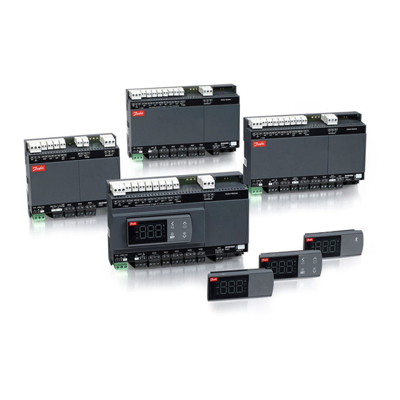
AK-CC55 Single Coil and Single Coil UI Portfolio overview The AK-CC55 portfolio contains four controllers with different functionalities and application settings, as outlined in the table. Table 1: AK-CC55 Portfolio AK-CC55 Compact AK-CC55 Single Coil AK-CC55 Single Coil UI AK-CC55 Multi Coil... -
Page 7: Connectivity
AK-CC55 Single Coil and Single Coil UI Connectivity The diagram outlines the connectivity options presented by AK-CC55 for the design of system functionality. Figure 2: Connectivity AKA 245: LON units only and max 250 controller parameters System Manager AK-CC55 Connect... -
Page 8: Ak-Cc55 Single Coil And Single Coil Ui
There are three versions available with different functions: • AK-UI55 Info: Temperature display. • AK-UI55 Set: Temperature display with control buttons on the front. • AK-UI55 Bluetooth: Temperature display with Bluetooth communication, for use with AK-CC55 Connect Mobile app. Figure 4: AK-UI55 Info... -
Page 9: Controller Functionality
AK-CC55 Single Coil and Single Coil UI Controller functionality Functions • Day/night thermostat with ON/OFF or modulating principle • Product sensor S6 with separate alarm limits • Switch between thermostat settings via digital input • Adaptive control of superheat • Adaptive defrosting based on diagnostics •... -
Page 10: Temperature Control
Accidental actuation may allow liquid throughput to the compressor. It is the installer’s responsibility to ensure that signal loss to the controller will not result in liquid throughput to the compressor. Danfoss accepts no responsibility for damage resulting from inadequate installation. -
Page 11: Night Setback Of Thermostat Value
AK-CC55 Single Coil and Single Coil UI signal on a digital input. Separate thermostat and alarm limits can be set for each thermostat band – also for the product sensor. Figure 7: Thermostat band function with two different band settings Night setback of thermostat value In refrigeration appliances there may be big load differences between the shop’s opening and closing hours,... -
Page 12: Appliance Shutdown
AK-CC55 Single Coil and Single Coil UI Table 5: Appliance cleaning function °C ÷ ÷ ÷ °C Appliance shutdown The function closes the AKV valve and all outputs are switched off. The cooling appliance is stopped like the “Main switch”, but this happens without an “A45 standby alarm”. The function can be enabled by a switch on the DI input or via a setting through data communication. -
Page 13: Stop Of Defrost
The controller has a built-in real-time clock which can be used to start defrosts. This clock has a power reserve of four days. If the controller is equipped with data communication, the clock will automatically be updated from a Danfoss system manager. -
Page 14: Adaptive Defrosting
Adaptive defrosting The Danfoss adaptive defrost algorithm detects the amount of ice build-up and cancels a scheduled defrost if it is not needed, or it can be set up to only perform defrost if the evaporator air flow is getting interrupted by frost or ice. -
Page 15: Melt Function
AK-CC55 Single Coil and Single Coil UI 4. Full adaptive: Full Adaptive mode is ideal for applications where defrost is not requested to be performed at a certain time, but can be performed whenever ice is starting to interrupt the airflow. It makes sense to combine this mode with the defrost interval timer as a safety timer. -
Page 16: Rail Heat
AK-CC55 Single Coil and Single Coil UI When the temperature has dropped to ”the middle of the differential”, the compressor with the longest operation time will be cut out. The running compressor will continue until the temperature has reached the cut-out value. Then it will cut out. -
Page 17: Fan
AK-CC55 Single Coil and Single Coil UI Figure 14: Rail heat control, dew point During defrosting During defrosting rail heat will be active, as selected in setting d27. Pulse control To obtain energy savings, it is possible to pulse control the power supply to the evaporator fans. -
Page 18: Night Blind
AK-CC55 Single Coil and Single Coil UI Here there are two operational options if data communication should fail: • The light can go ON • The light can stay in its current mode The light load must be connected to the NC terminals on the relay. -
Page 19: Heating Function (Only With Custom Set-Up)
AK-CC55 Single Coil and Single Coil UI It can be defined whether humidity control is active during defrost or not. Figure 17: Humidifier control Humidity 100% Humidity diff. Time Humidifier If the humidity gets below the SP, then humidification is started via a DO signal to a humidifier. -
Page 20: Digital Inputs
AK-CC55 Single Coil and Single Coil UI Figure 19: Heating function Refrigeration º C Neutral zone Heat Digital inputs There are two digital inputs, DI1 and DI2, with dry contact function, and one digital input DI3 with high voltage signal. -
Page 21: Door Contact
AK-CC55 Single Coil and Single Coil UI Via a setting (see o90 Fan at forced closing) it is possible to define whether the fan should be ON or OFF during forced closing and whether an ongoing defrost is suppressed (i.e. put in standby position for a period of up 10... - Page 22 AK-CC55 Single Coil and Single Coil UI Master control function Description Master control signal used for co-ordinated defrost control to hold cabinets from returning to normal refrigeration after a defrost MC Hold after defrost until all cabinets have terminated defrost MC Stop defrost Master control signal used to prevent a defrost start in a controller.
-
Page 23: Applications
AK-CC55 Single Coil and Single Coil UI Applications The chapter outlines application examples: • Standard display case • Cases with one valve, one evaporator and two refrigeration sections • Cases with one valve, two evaporators and two refrigeration sections • Cold rooms An application setting will configure inputs and outputs so that the controller’s operation interface is reflecting the... -
Page 24: Ak-Cc55 Connections And Application Options
30 31 AK-CC55 Single Coil is optimised for control of one expansion valve + different combinations of light, rail heat and alarm relays. It has 6 Digital Outputs (DO), known as DO1 – DO6, one Analogue Output (AO), known as AO1, 6 Analogue Inputs (AI), known as AI1 –... -
Page 25: Application Set-Ups And Io Connections
AK-CC55 Single Coil and Single Coil UI = Optional use Table 10: Sensor description Evaporating pressure Gas outlet of evaporator Return air temperature Discharge air temperature Evaporator temperature Product temperature Return air temperature on second cooling section Evaporator temperature on second evaporator... - Page 26 AK-CC55 Single Coil and Single Coil UI Figure 27: Connections for application 2 1 3 2 41 42 43 44 45 46 47 48 49 50 51 52 53 54 60 61 70 71 83 84 DI1/ MODBUS 115 – 230 V AC Railheat Comp.
- Page 27 AK-CC55 Single Coil and Single Coil UI Figure 30: Connections for application 5 1 3 2 41 42 43 44 45 46 47 48 49 50 51 52 53 54 60 61 70 71 83 84 DI1/ MODBUS 115 – 230 V AC...
-
Page 28: Product Identification
AK-CC55 Single Coil and Single Coil UI Figure 33: Connections for application 8 1 3 2 0 10 41 42 43 44 45 46 47 48 49 50 51 52 53 54 60 61 70 71 83 84 DI1/ MODBUS 115 –... -
Page 29: Ak-Cc55 Single Coil Connections
AK-CC55 Single Coil and Single Coil UI AK-CC55 Single Coil connections Data communication Figure 36: Data communication IMPORTANT: It is important that the installation of the data communication cable is performed correctly with sufficient distance to high voltage cables. -
Page 30: Aks 32R Info
Figure 40: Coordinated defrost via cable connections Max. 10 The following controllers can be connected in this way: EKC 204A, AK-CC 210, AK-CC 250, AK-CC 450, AK-CC 550 and AK-CC55. Refrigeration is resumed at the same time when all controllers have terminated defrost. External display AK-UI55... -
Page 31: Connections
• Terminal 83 = B- • Terminal 84 = A+ • Terminal 85 = screen NOTE: When replacing AK-CC 550 with AK-CC55 A+, B- and shield must be switched. Supply voltage • 230 V AC or 115 V AC • AKV valve Connection of expansion valve type AKV, AKVA, AKVH or AKVP. - Page 32 For one display the max. cable length is 100 m. For two displays the sum of the two cable lengths must not exceed 100 m. NOTE: When replacing AK-CC 550 with AK-CC55, AKA 16X remote displays and cables have to be replaced with new AK- UI55 displays and cables. Electric noise...
- Page 33 Electronic controls are no substitute for normal, good engineering practice. Danfoss will not be responsible for any goods, or plant components, damaged as a result of the above defects. It is the installer's responsibility to check the installation thoroughly, and to fit the necessary safety devices.
-
Page 34: Replacing Ak-Cc 550 With Ak-Cc55
AK-CC55 Single Coil and Single Coil UI Replacing AK-CC 550 with AK-CC55 NOTE: Be aware when exchanging an AK-CC 550 controller with a new AK-CC55 controller - new wiring principles! Table 12: Replacing AK-CC 550 with AK-CC55 AK-CC 550 AK-CC55 Pressure sensor has new connection –... -
Page 35: Operation
• Via AK-UI55 Bluetooth display Operation via data communication Via system manager's display All AK-CC55 controllers can be operated from a central location, e.g. AK-SM 800. Data communication is to take place via MODBUS or Lon. Via system manager and service tool Operation can also be performed from a central location with PC software "Service Tool"... - Page 36 • When FAc is shown in the display, select "yes" NOTE: The OEM factory setting will either be the Danfoss factory settings or a user defined factory setting if one has been made. The user can save his setting as OEM factory setting via parameter o67.
-
Page 37: Parameter Groups When Operating Via Display
AK-CC55 Single Coil and Single Coil UI Parameter groups when operating via display Figure 43: SET button parameter list SET button, 3 s: Configuration settings PS: Password (if any) (PS) Main switch Application MODBUS address Food type Cut-out temperature Refrigerant type Min. - Page 38 AK-CC55 Single Coil and Single Coil UI Open parameter r89 and set the number for the array of presettings. The few selected settings will now be transferred to the menu Set the desired cut-out temperature r00 Select refrigerant via parameter o30 Set the pressure transmitter min.
-
Page 39: Ak-Ui55 Display Menu (Sw Ver. 1.5X)
AK-CC55 Single Coil and Single Coil UI AK-UI55 display menu (SW ver. 1.5x) If the operation is protected by one or more passwords, reading and setting the parameter will be limited to: R or W This setting can be seen with password no. _ or higher (3 is the highest level). -
Page 40: Compressor
AK-CC55 Single Coil and Single Coil UI Function Values Code Min. value Max. value Fact. value S6 Low alarm limit 1 -50.0 °C 50.0 °C -30.0 °C S6 High alarm limit 2 -50.0 °C 50.0 °C 8.0 °C S6 Low alarm limit 2 -50.0 °C... -
Page 41: Injection Control
AK-CC55 Single Coil and Single Coil UI Injection control Table 19: Injection control Function Values Code Min. value Max. value Fact. value Max. superheat limit 20.0 °C 12.0 °C Min. superheat limit 2.0 °C 3.0 °C MOP temperature -50.0 °C 15.0 °C... -
Page 42: Miscellaneous
AK-CC55 Single Coil and Single Coil UI Function Values Code Min. value Max. value Fact. value Humidity alarm delay 0 min 240 min 60 min Humidity ctrl. at defrost 0=No, 1=Yes Humidity sensor - Min sig- 0 RH% 0RH% Humidity sensor - Max sig-... - Page 43 AK-CC55 Single Coil and Single Coil UI Function Values Code Min. value Max. value Fact. value DI2 Configuration 0=None, 1=DI status, 2=Door function, 3=Door alarm, 4=Defrost start, 5=Main switch, 6=Night setback, 7=Thermostat band, 8=Alarm at closed, 9=Alarm at open, 10=Case...
-
Page 44: Control
AK-CC55 Single Coil and Single Coil UI Control Table 24: Control Function Values Code Min. value Max. value Fact. value 0=Not used, 1=High Priori- Alarm relay priority ty, 2=Medium priority, 3=All Blinds max. open time 0 min 60 min 5 min... -
Page 45: Service
AK-CC55 Single Coil and Single Coil UI Function Values Code Min. value Max. value Fact. value Hot gas valve - override 0=MAN OFF, 1=MAN ON Blinds - override 0=MAN OFF, 1=MAN ON Defrost B - override 0=MAN OFF, 1=MAN ON... - Page 46 AK-CC55 Single Coil and Single Coil UI Function Values Code Min. value Max. value Fact. value Night condition 0=OFF, 1=ON S4 Air OFF evap. A -200.0 °C 200.0 °C 0.0 °C Thermostat air temp. A -200.0 °C 200.0 °C 0.0 °C...
-
Page 47: Operation Via Ak-Ui55 Bluetooth
AK-CC55 Single Coil and Single Coil UI Operation via AK-UI55 Bluetooth Access to parameters via Bluetooth and app App can be downloaded from App Store and Google Play. ◦ Name = AK-CC55 Connect ◦ Start the app. Click on the display’s Bluetooth button for 3 seconds. -
Page 48: Ak-Cc55 Connect Menu (Sw Ver. 1.5X)
AK-CC55 Single Coil and Single Coil UI AK-CC55 connect menu (SW ver. 1.5x) Start / Stop Table 27: Start/Stop Function Description Values Code Short name Main switch Start / stop of refrigeration. With this setting refrigera- -1=Manual, 0=Stop, 1=Start r12 Main switch tion can be started, stopped or a manual override of the outputs can be allowed. - Page 49 AK-CC55 Single Coil and Single Coil UI Function Description Values Code Short name DI3 Configuration Select the function of the digital input 0=None, 1=DI status, 2=Door function, 3=Door alarm, o84 DI3 Config 4=Defrost start, 5=Main switch, 6=Night setback, 7=Thermostat band, 8=Alarm at closed, 9=Alarm at...
-
Page 50: Thermostat Control
AK-CC55 Single Coil and Single Coil UI Thermostat control Table 29: Thermostat control Function Description Values Code Short name Control state A Readout of the actual control state of the controller 0=Normal ctrl., 1=Hold after defrost, 2=Min ON timer, u00 Ctrl. state... -
Page 51: Alarm Limits And Delays
AK-CC55 Single Coil and Single Coil UI Function Description Values Code Short name S4 frost protection Frost protection on S4 air temperature. If the S4 tem- r98 S4 Min Lim perature sensor measure a temperature lower than the set limit, refrigeration will be stopped in order to protect products from ice formation. -
Page 52: Humidity Control
AK-CC55 Single Coil and Single Coil UI Function Description Values Code Short name Alarm delay pull Alarm delay at tempeature pull down conditions A12 Pulldown del down A (long alarm delay). This time delay is used during start-up, during defrost and immediately after a de- frost. -
Page 53: Injection Control
AK-CC55 Single Coil and Single Coil UI Function Description Values Code Short name Humidity sensor - h29 RH Min Value Min signal Humidity sensor - h30 RH Max Value Max signal Humidity ctrl. at de- Select how to control humidity during defrost:No: Hu-... -
Page 54: Defrost Control
AK-CC55 Single Coil and Single Coil UI Defrost control Table 33: Defrost control Function Description Values Code Short name Control state A Readout of the actual control state of the controller 0=Normal ctrl., 1=Hold after defrost, 2=Min ON timer, u00 Ctrl. state... - Page 55 AK-CC55 Single Coil and Single Coil UI Function Description Values Code Short name Time staggering Time staggering for defrost cut-ins during start-up d05 Time stagg. power-up The function is only relevant if you have several refrig- eration appliances or groups where you want the de- frost to be staggered in relation to one another.
-
Page 56: Defrost Schedules
AK-CC55 Single Coil and Single Coil UI Defrost schedules Table 34: Defrost schedules Function Description Values Code Short name Defrost schedule 0=No, 1=Yes t00 Def.Schedule Def. start 1 - Hours Time in hours for start of defrost t01 Def. 1 hr. -
Page 57: Fan Control
AK-CC55 Single Coil and Single Coil UI Fan control Table 36: Fan control Function Description Values Code Short name Control state A Readout of the actual control state of the controller 0=Normal ctrl., 1=Hold after defrost, 2=Min ON timer, u00 Ctrl. state... -
Page 58: Light/Blinds/Cleaning Control
AK-CC55 Single Coil and Single Coil UI Function Description Values Code Short name Rail heat PWM - Peri- Period time for the pulse width modulation P82 RailCyclePWM od time Rail heat min. ON cy- Lowest permitted rail heat power. When the meas-... -
Page 59: Alarm Relay Priorities
AK-CC55 Single Coil and Single Coil UI Function Description Values Code Short name Display air S4% Signal to the display sensor. Here you have to define o17 Disp. S4 % the ratio between the sensors which the display has to use. S3, S4 or a combination of the two. With set- ting 0% only S3 is used. -
Page 60: Miscellaneous
AK-CC55 Single Coil and Single Coil UI Miscellaneous Table 41: Miscellaneous → Access codes Function Description Values Code Short name Access code 3 Access code for local display o05 Acc. code 3 Access code 2 Access code for local display o64 Acc. - Page 61 Air tuning value Expert setting - contact Danfoss for further informa- --- AD AirTuning tion New air tuning value Expert readout - contact Danfoss for further informa- --- NewAirTunVal tion Little ice indicator Expert readout - contact Danfoss for further informa- --- FaultIndic.0...
-
Page 62: Fault Message
AK-CC55 Single Coil and Single Coil UI Function Description Values Code Short name MC Case shutdown Master control signal used to shut down a case for a 0=OFF, 1=ON --- Case shutdwn time period. During shutdown there will be no alarm... - Page 63 AK-CC55 Single Coil and Single Coil UI Code Alarm text Description The S6 Product temperature has been below the min alarm limit for a longer time period than the set alarm S6 low product temperature A delay. DI alarm 1...
-
Page 64: Operating Status
AK-CC55 Single Coil and Single Coil UI Operating status Table 49: Operating status Ctrl. State/ Operating status Description Code Push the info button for 3 seconds to see status. If there is a status code, it will be shown on the display. The individual status codes have the following meanings: Normal ctrl. -
Page 65: Product Specification
AK-CC55 Single Coil and Single Coil UI Product specification Technical data Electrical specifications Table 50: Electrical specifications Electrical data Value Supply voltage AC [V] 115 V / 230 V, 50/60 Hz Voltage variation range max. [V] 85 – 265 V... -
Page 66: Function Data
AK-CC55 Single Coil and Single Coil UI NOTE: • DO2 to DO6 are 16 A relays. • Max. load must be observed. • DO5 / DO6 is recommended for load with high inrush current e.g. EC Fan and LED light. -
Page 67: Certificates, Declarations, And Approvals
Some approvals may change over time. You can check the most current status at danfoss.com or contact your local Danfoss representative if you have any questions. -
Page 68: Statements For The Ak-Ui55 Bluetooth Display
AK-CC55 Single Coil and Single Coil UI Statements for the AK-UI55 Bluetooth display FCC COMPLIANCE STATEMENT CAUTION: Changes or modifications not expressly approved could void your authority to use this equipment This device complies with Part 15 of the FCC Rules. Operation to the following two conditions: (1) This device may not cause harmful interference, and (2) this device must accept any interference received, including interference that may cause undesired operation. -
Page 69: Online Support
App Store Danfoss can accept no responsibility for possible errors in catalogues, brochures and other printed material. Danfoss reserves the right to alter its products without notice. This also applies to products already on order provided that such alterations can be made without subsequential changes being necessary in specifications already agreed.
Need help?
Do you have a question about the AK-CC55 and is the answer not in the manual?
Questions and answers