Danfoss AK-CC55 User Manual
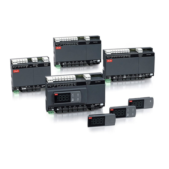
Controller for appliance control
Hide thumbs
Also See for AK-CC55:
- User manual (69 pages) ,
- Installation manual (18 pages) ,
- User manual (64 pages)

Subscribe to Our Youtube Channel
Related Manuals for Danfoss AK-CC55


Summary of Contents for Danfoss AK-CC55
- Page 1 User Guide Controller for appliance control AK-CC55 ADAP-KOOL® Refrigeration control systems...
- Page 2 User Guide | Controller for appliance control, AK-CC55 Contents Introduction ....................... 2 Functions ......................39 Programme overview ..................4 Survey of functions ..................47 Applications ....................... 6 Connections .....................65 Operation ......................16 Data ........................68 Menu survey — Compact version ............20 Ordering ......................69 Menu survey — Single Coil version ............26 Menu survey —...
- Page 3 User Guide | Controller for appliance control, AK-CC55 Applications Here you can find application examples: • Standard display case • Cases with one valve, one evaporator and two refrigeration sections • Cases with one valve, two evaporators and two refrigeration sections •...
- Page 4 User Guide | Controller for appliance control, AK-CC55 Programme overview AK-CC55 Compact Compact version for controlling one evaporator. A setting will configure inputs and outputs for the desired use. There are nine applications to choose from: Regulation can be performed using an AKV...
- Page 5 User Guide | Controller for appliance control, AK-CC55 Primary function differences between the three controllers Application Compact Single Coil Multi Coil EEV - application (electrically operated expansion valve) TEV - application (thermostatic expansion valve + solenoid valve or compressor) Remote hot gas - application...
- Page 6 User Guide | Controller for appliance control, AK-CC55 Applications Here is an overview of the controller’s application options. An application setting will configure the relay outputs so that the controller's IO configuration is aimed at the selected application. Wiring diagrams can be seen on the following pages.
- Page 7 User Guide | Controller for appliance control, AK-CC55 Compact Control of one evaporator + different combinations of light, rail heat and alarm relays. The most important variations are: 1-4: TEV applications Control of compressor or solenoid valve, alarm relay, lights, rail heat 4: Configurable outputs, e.g.: Dual compressor operation, heat...
- Page 8 User Guide | Controller for appliance control, AK-CC55 40 41 42 43 44 45 46 47 48 49 50 60 61 70 71 83 84 85 MODBUS Comp. 115 - 230V AC 10 11 12 13 14 Custom set-up 40 41 42...
- Page 9 User Guide | Controller for appliance control, AK-CC55 40 41 42 43 44 45 46 47 48 49 50 60 61 70 71 83 84 85 MODBUS 115 - 230V AC Light Defrost 10 11 12 13 14 40 41 42...
- Page 10 User Guide | Controller for appliance control, AK-CC55 Single Coil Control of one expansion valve + different combinations of light, rail heat and alarm relays. The controller covers the following nine applications: 1-3: Plugin cabinets with different output combinations of alarm,...
- Page 11 User Guide | Controller for appliance control, AK-CC55 © Danfoss | DCS (vt) | 2019.09 BC308437742037en-000101 | 11...
- Page 12 User Guide | Controller for appliance control, AK-CC55 Custom set-up 12 | BC308437742037en-000101 © Danfoss | DCS (vt) | 2019.09...
- Page 13 User Guide | Controller for appliance control, AK-CC55 Multi Coil Control of one to three expansion valves, lights and different combinations of rail heat and alarm relays. The most important variations are: 1-3: Control of one, two and three evaporators.
- Page 14 User Guide | Controller for appliance control, AK-CC55 Rail heat Alarm AKV B AKV C 13 14 23 24 0-10 Heat AKV A Alarm AKV B Humidity 13 14 23 24 Alarm AKV B Defrost A Defrost B 13 14...
- Page 15 User Guide | Controller for appliance control, AK-CC55 Connection labels The controller is provided with labels from the factory, indicating a generic application. When selecting the required application, specific labels are provided so that you can mount the relevant one.
- Page 16 100 metres from the controller. Smart phone and app There is an app available - "AK-CC55 connect". It can be downloaded freely to a compatible iOS/Android smartphone device. The functions can be seen later in this document.
- Page 17 User Guide | Controller for appliance control, AK-CC55 AK-UI55 Bluetooth Displayinfo: Access to parameters via Bluetooth and app 1. App can be downloaded from Google App Store and Google Play Name = AK-CC55 Connect The operation is locked and cannot be operated via Start the app.
- Page 18 User Guide | Controller for appliance control, AK-CC55 Display AK-UI55 Set The values will be shown with three digits, and with a setting you can determine whether the temperature is to be shown in °C or in °F. Lights in event of alarm — press on alarm button — alarm relay is reset — alarm code displayed — e.g. “A1”...
- Page 19 User Guide | Controller for appliance control, AK-CC55 Parameter grouping at display operation SET button, 3 s: Configuration settings PS: Password (if any) Info button, 3 s: Information for service use (PS) Main switch Þ See control status message (on page 62).
- Page 20 User Guide | Controller for appliance control, AK-CC55 Menu survey — Compact version Overview of outputs and applications AI5/ Application AO1 AI1 AI2 AI3 AI4 • • • • • • • • • • • • • • •...
- Page 21 User Guide | Controller for appliance control, AK-CC55 Compact - continued Code Min. Max. Fac. Actual Alarms Delay for temperature alarm 1 0 min. 240 min. Delay for door alarm 1 0 min. 240 min. Delay for temperature alarm after defrost 1 0 min.
- Page 22 User Guide | Controller for appliance control, AK-CC55 Compact - continued Code Min. Max. Fac. Actual Fan stop temperature (S5) 1 -50 °C 50 °C Pulse operation on fans: 0=No pulse operation, 1=At thermostat cut-outs only, 2= Only at thermostat...
- Page 23 User Guide | Controller for appliance control, AK-CC55 Compact - continued Code Min. Max. Fac. Actual Refrigerant setting: 1-3* 1=User defined. 3-digits. 2=R22. 3=R134a. 4=R502. 5=R717. 6=R13. 7=R13b1. 8=R23. 9=R500. 10=R503. 11=R114. 12=R142b. 13=User defined. 14=R32. 15=R227. 16=R401A. 17=R507. 18=R402A. 19=R404A.
- Page 24 User Guide | Controller for appliance control, AK-CC55 Compact - continued Code Min. Max. Fac. Actual Configuration of alarm relay: The alarm relay will be activated by an alarm in one or more of the following priorities. Setting: 0 = The relay is not activated by alarms...
- Page 25 User Guide | Controller for appliance control, AK-CC55 Compact - continued Code Status on night operation (on or off ) 1=on Temperature measured with S4 sensor Thermostat temperature Run time of thermostat (cooling time) in minutes Temperature of S2 evaporator outlet temp.
- Page 26 User Guide | Controller for appliance control, AK-CC55 Menu survey — Single Coil version Overview of outputs and applications AI7/ Application AO1 AI1 AI2 AI3 AI4 AI5 AI6 DI2 DI3 • • • • • • • • • • • •...
- Page 27 User Guide | Controller for appliance control, AK-CC55 Single Coil - continued Code Min. Max. Fac. Actual Alarms Delay for temperature alarm 1 0 min. 240 min. Delay for door alarm 1 0 min. 240 min. Delay for temperature alarm after defrost 1 0 min.
- Page 28 User Guide | Controller for appliance control, AK-CC55 Single Coil - continued R-W Code Min. Max. Fac. Actual Injection control function Max. value of superheat reference 1 "n10" 20 °C Min. value of superheat reference 1 2 °C "n09" MOP temperature. Off if MOP temp. = 15.0 °C 1 -50 °C...
- Page 29 User Guide | Controller for appliance control, AK-CC55 Single Coil - continued R-W Code Min. Max. Fac. Actual Miscellaneous Delay of output signals after power failure 1 0 sec 600 sec Input signal on DI1. Function: 1-2* o02 0=not used. 1=status on DI1. 2=door function with alarm when open.
- Page 30 User Guide | Controller for appliance control, AK-CC55 Single Coil - continued R-W Code Min. Max. Fac. Actual Access code 2 (partial access) Replace the controller's factory settings with the 3-3* o67 1 0/Off 1/On 0/Off present settings Input signal on DI3. Function: (high voltage input) 1-2* o84 0=not used.
- Page 31 User Guide | Controller for appliance control, AK-CC55 Single Coil - continued R-W Code Min. Max. Fac. Actual Configuration of relay output DO3: 0=not used, 1=fan, 1-3* q03 2=fan Eco, 3=defrost, 4=rail heat, 5=alarm, 6=light, 7=night blinds, 8=compressor, 9=compressor 2,...
- Page 32 User Guide | Controller for appliance control, AK-CC55 Single Coil - continued R-W Code Status on relay for compressor/solenoid valve Status on relay for fan Status on relay for defrost Status on relay for rail heat Status on relay for alarm...
- Page 33 User Guide | Controller for appliance control, AK-CC55 Menu survey — Multi Coil version Overview of outputs and applications AI7/ Application AO1 AI1 AI2 AI3 AI4 AI5 AI6 DI2 DI3 • • • • • • • • • •...
- Page 34 User Guide | Controller for appliance control, AK-CC55 Multi Coil - continued Code Min. Max. Fac. Actual Low alarm limit for thermostat 2 1 -50 °C 50 °C Alarm time delay or signal on the DI1 input 0 min. 240 min.
- Page 35 User Guide | Controller for appliance control, AK-CC55 Multi Coil - continued Code Min. Max. Fac. Actual Humidity Setpoint for cut-in of humidity function 100 % Difference for humidity function 30 % Alarm limit for high humidity (too damp) 100 %...
- Page 36 User Guide | Controller for appliance control, AK-CC55 Multi Coil - continued Code Min. Max. Fac. Actual Appliance cleaning. 0=no Appliance cleaning. 1=Fans only. 2=All output Off. Selection of wiring diagram. See overview on pages 13-14 1-3* Access code 2 (partial access)
- Page 37 User Guide | Controller for appliance control, AK-CC55 Multi Coil - continued Code Min. Max. Fac. Actual Define which food temperature measurement to display in U72: 1-2* 1 = Air temperature section A 2 = Average air temperature of all sections...
- Page 38 User Guide | Controller for appliance control, AK-CC55 Multi Coil - continued Code Actual defrost time (minutes) section C Actual S4 temperature section C Thermostat temperature section C Runtime of thermostat (cooling time) in minutes section C Temperature of evaporator outlet temp. section C...
- Page 39 User Guide | Controller for appliance control, AK-CC55 Functions Liquid injection Liquid injection in the evaporator is controlled by an electronic injection valve of the type AKV. The valve operates as both expansion valve and solenoid valve. The controller opens and closes the valve based on sensor readings.
- Page 40 User Guide | Controller for appliance control, AK-CC55 Temperature monitoring Just as is possible for the thermostat, the alarm monitoring can be set with a weighting between S3 and S4 so that you can decide how much the two sensor values should influence the alarm monitoring.
- Page 41 User Guide | Controller for appliance control, AK-CC55 Defrost Stop of defrost Depending on the application, you may choose between the Defrosting can be stopped by either: following defrost methods: • Time Natural: Here the fans are kept operating during the defrost •...
- Page 42 User Guide | Controller for appliance control, AK-CC55 Coordinated defrost Max. 10. There are two ways in which coordinated defrost can be arranged. Either with wire connections between the controllers or via data communication: Wire connections The digital input DI2 must be configured for coordinated defrost and wiring must be connected between the relevant controllers.
- Page 43 User Guide | Controller for appliance control, AK-CC55 Melt function This function will prevent the air flow in the evaporator from being reduced by frost created by uninterrupted operation for a long time. The function is activated if the thermostat temperature has remained in the range between -5°C and +10°C for a longer...
- Page 44 User Guide | Controller for appliance control, AK-CC55 • One where the effect must be min. (o86). The light load must be connected to the NC terminals on the relay. At a dew point which is equal to or lower than the value in 086, This ensures that the light remains on in the appliance if power to the effect will be the value indicated in o88.
- Page 45 User Guide | Controller for appliance control, AK-CC55 Digital inputs Function Input / Settings menu Setting There are two digital inputs, DI1 and DI2, with dry contact function, and one digital input DI3 with high voltage signal. They can be used for the following functions:...
- Page 46 User Guide | Controller for appliance control, AK-CC55 Data communication The controller has built-in MODBUS data communication. If there is a requirement for a different form of data communication, a Lon RS 485 module can be inserted in the controller.
- Page 47 User Guide | Controller for appliance control, AK-CC55 Survey of functions Function Para- Parameter by operation via data meter communication Normal display Normally the temperature value from one of the two thermostat sensors S3 or S4 or a Display air (u56) mixture of the two measurements is displayed.
- Page 48 User Guide | Controller for appliance control, AK-CC55 Melt function MeltInterval Only for control of refrigeration (-5 to +10°C). The function ensures that the evaporator will not be blocked by frost. Here you set how often the function is to stop the refrigeration and hence transform the frost to water (or ice if there is too much frost).
- Page 49 User Guide | Controller for appliance control, AK-CC55 Lower alarm limit LowLim Air Here you set when the alarm for low temperature is to start. The limit value is set in °C (absolute value). Upper alarm limit for thermostat 2 (Thermostat band 2)
- Page 50 User Guide | Controller for appliance control, AK-CC55 Defrost Defrost control The controller contains a timer function that is zero-set after each defrost start. The timer function will start a defrost if/when the interval time is passed. The timer function starts when voltage is connected to the controller, but it is displaced the first time by the setting in d05.
- Page 51 User Guide | Controller for appliance control, AK-CC55 Delay of fan start after defrost FanStartDel Here you set the time that is to elapse from compressor start after a defrost and until the fan may start again. (The time when water is “tied” to the evaporator).
- Page 52 Info 1. Superheat regulation can be changed from adaptive regulation to load-defined superheating. Changes are to be made in menu n21 "For Danfoss only". 2. For regulation with "zero degree superheat" (adaptive liquid regulation), the set- ting values for superheating can be seen in P86 and P87.
- Page 53 User Guide | Controller for appliance control, AK-CC55 Internal defrosting schedule/clock function Start/stop of internal defrosting forms Def. Schedule Off: The subsequent defrosting schedule is not used. A defrost start signal is issued by the system unit. On: The subsequent settings are used. Up to 6 individual times can be set for the defrost start throughout the day.
- Page 54 User Guide | Controller for appliance control, AK-CC55 Digital input signal - DI1 DI 1 Config. The controller has a digital input 1 which can be used for one of the following The definition happens with the functions: number value shown to the left.
- Page 55 User Guide | Controller for appliance control, AK-CC55 Refrigerant setting (only if "r12" = 0) Refrigerant Before refrigeration is started, the refrigerant must be defined. You may choose between the following refrigerants: 1=User defined with 3 digits, see P83-85. 2=R22. 3=R134a. 4=R502. 5=R717. 6=R13.
- Page 56 User Guide | Controller for appliance control, AK-CC55 Appliance cleaning Case clean The status of the function can be followed here or the function can be started manually. 0 = Normal operation (no cleaning) 1 = Cleaning with fans operating. All other outputs are Off.
- Page 57 User Guide | Controller for appliance control, AK-CC55 Defrosting and fan operation during forced closing Mode ForcedCl You can set whether fans should be operational or stopped if the function “Forced closing” is activated here. 0: The fans will be stopped and defrosting will be permitted.
- Page 58 User Guide | Controller for appliance control, AK-CC55 DO2-DO6 application: The following relay outputs can be dedicated to a specific function. But only for application 9 in Single coil and application 4 and 9 in Compact version: 0=not used, 1=fan, 2=fan Eco, 3=defrost, 4=rail heat, 5=alarm, 6=lights, 7=night blind,...
- Page 59 User Guide | Controller for appliance control, AK-CC55 Food temperature Food sensor Defines the temperature measurements that will be shown in U72: Compact : 1=thermostat temperature, 2=alarm temperature, 3=S3 Single Coil : 1=thermostat temperature, 2=alarm temperature, 3=S3, 4=S6 Multi Coil : 1=thermostat temperature section A, 2=average of all sections,...
- Page 60 User Guide | Controller for appliance control, AK-CC55 Service Service Operating status. Please refer to the overview on page 62 Ctrl. state Temperature measured with S5 sensor S5 temp. Status on DI1 input. on/1=closed DI1 status Read the duration of the ongoing defrost or the duration of the last completed...
- Page 61 User Guide | Controller for appliance control, AK-CC55 Readout of alarm air temp. Section B Alarm air B Readout of display 2 value Display air2 Status of the relay for the Eco fan Fan Eco Display of signal quality for the MODBUS communication Comm.
- Page 62 User Guide | Controller for appliance control, AK-CC55 Operating status (Measurement) The controller goes through some regulating situations where it is just waiting for Ctrl. state: the next point of the regulation. To make these “why is nothing happening” situations (Appears in all menu images) visible, you can see an operating status on the display.
- Page 63 User Guide | Controller for appliance control, AK-CC55 Fault message In an error situation the alarm LED on the front will flash and the alarm relay will be activated (depending on priority). If you push the top button for 3 seconds you can see the alarm report in the display.
- Page 64 User Guide | Controller for appliance control, AK-CC55 Data communication The importance of individual alarms can be defined with a setting. The setting must be carried out in the group "Alarm destinations" Settings from Settings from Alarm relay Send via...
- Page 65 User Guide | Controller for appliance control, AK-CC55 Connections Overview of outputs and applications. Compact 40 41 42 43 44 45 46 47 48 49 50 60 61 70 71 83 84 85 See also electrical diagrams pages 7-14. MODBUS...
- Page 66 See drawing on page 39. Light Please note: when replacing AK-CC550 with AK-CC55, S and There is connection between terminal 10 and 12 when the ground must be switched. function is on.
- Page 67 Special reference is made to the necessity of signals to the controller when the compressor is stopped and to the need of liquid receivers before the compressors. Your local Danfoss agent will be pleased to assist with further advice, etc. AKV info...
- Page 68 User Guide | Controller for appliance control, AK-CC55 Data 115 / 230 V AC (85-265 V). 5 VA, 50/60 Hz Supply voltage Power: Green LED Sensor S2, S6 Pt 1000 Pt 1000 or PTC 1000 or Ntc5K or Ntc10K Sensor S3, S4, S5 (All 3 must be of the same type) PT 1000: -60 –...
- Page 69 User Guide | Controller for appliance control, AK-CC55 Ordering Type Function Code no. 084B4081 AK-CC55 Compact Case controller with one AKV or solenoid valve AK-CC55 Single Coil Case controller with one AKV valve 084B4082 Case controller with one AKV valve...
- Page 70 © Danfoss | DCS (vt) | 2019.09 BC308437742037en-000101 | 70...
Need help?
Do you have a question about the AK-CC55 and is the answer not in the manual?
Questions and answers