
Related Manuals for ProSoft Technology ILX69-PBM


Summary of Contents for ProSoft Technology ILX69-PBM
- Page 1 ILX69-PBM CompactLogix™ or MicroLogix™ Platform PROFIBUS Master Communication Module November 9, 2020 USER MANUAL...
-
Page 2: Your Feedback Please
November 9, 2020 ® ProSoft Technology , is a registered copyright of ProSoft Technology, Inc. All other brand or product names are or may be trademarks of, and are used to identify products and services of, their respective owners. ®... -
Page 3: Table Of Contents
2.3.2 Communication Stop During Firmware Update ............11 Safety Instructions to Avoid Property Damage ............12 2.4.1 Device Destruction if ILX69-PBM is Installed to Powered PLC ......12 2.4.2 Device Destruction by Exceeding Allowed Supply Voltage ........12 2.4.3 Device Destruction by Exceeding Allowed Signaling Voltage ........ 12 2.4.4... - Page 4 Creating a New ILX69-PBM Project ............... 34 5.2.2 PROFIBUS Master Configuration ................36 5.2.3 PROFIBUS Slave Configuration ................37 Downloading the Project to the ILX69-PBM ............42 5.3.1 Assigning an IP Address ..................42 5.3.2 Downloading the Project ..................44 Adjusting Input/Output Data Lengths in the Project ..........
- Page 5 ILX69-PBM ♦ CompactLogix™ or MicroLogix™ Platform Introduction PROFIBUS Master Communication Module User Manual 7.2.2 ILX69-PBM LEDs ....................102 Troubleshooting ....................104 Technical Data Technical Data - ILX69-PBM ................105 Technical Data - PROFIBUS ................107 Annex PROFIBUS Functionality ..................108 9.1.1...
-
Page 6: Introduction
General Information The ILX69-PBM is a PROFIBUS DP master module for the CompactLogix™ platform which allows the PLC to control data exchange on a PROFIBUS network. The ILX69- PBM handles the cyclic data exchange between the connected PROFIBUS slaves. -
Page 7: Reference Systems
PROFIBUS Master Communication Module User Manual The configuration and diagnostics of the ILX69-PBM is done using the ProSoft fdt Configuration Manager software over an Ethernet connection. The configuration is stored permanently using the on-board FLASH memory of the ILX69-PBM and is available immediately on power up. -
Page 8: 1769 Programmable Controller Functionality
CompactLogix™ 1769-L31 CompactLogix™ 1769-L32E CompactLogix™ 1769-L33ER CompactLogix™ 1769-L35E CompactLogix™ 1769-L36ERM (*) Only one ILX69-PBM is supported on the bus due to power restrictions. Yes = Functionality supported No = Functionality not supported Requirements 1.5.1 Software Requirements The software requirements for using the ILX69-PBM within a CompactLogix™ system are listed below. -
Page 9: System Requirements
SYCON.net and legacy PROSOFT.fdt cannot be and shall not be installed, and vice- versa. 1.5.3 Hardware Requirements The following minimum hardware is required to use the ILX69-PBM: Windows PC for the ProSoft fdt Configuration Manager software (advantageous with SD card slot or SD card reader). Refer to section System Requirements (page 9). -
Page 10: Safety
Technical knowledge is presumed. The user must assure that all legal regulations are obeyed. Personnel Qualification The ILX69-PBM must only be installed, configured, and removed by qualified personnel. Job-specific technical skills for people professionally working with electricity must be present concerning the following topics: ... -
Page 11: Communication Stop During Firmware Update
ILX69-PBM ♦ CompactLogix™ or MicroLogix™ Platform Safety PROFIBUS Master Communication Module User Manual An electrical shock is the result of a current flowing through the human body. The resulting effect depends on the intensity and duration of the current and on its path through the body. -
Page 12: Safety Instructions To Avoid Property Damage
Strictly obey to all safety rules provided by the PLC device manufacturer documentation. Shut off the power supply of the PLC, before you install the ILX69-PBM module. 2.4.2 Device Destruction by Exceeding Allowed Supply Voltage To avoid device destruction due to high supply voltage to the ILX69-PBM, you must observe the following instructions. -
Page 13: Electrostatically Sensitive Devices
Touch a grounded object to discharge potential static. Wear an approved grounding wrist strap. Do not touch connectors or pins on the ILX69-PBM. Do not touch circuit components inside the equipment. If available, use a static-safe workstation. -
Page 14: Labeling Of Safety Messages
Safety ILX69-PBM ♦ CompactLogix™ or MicroLogix™ Platform User Manual PROFIBUS Master Communication Module Labeling of Safety Messages The Safety Messages at the beginning of a chapter are pinpointed particularly and highlighted by a signal word according to the degree of endangerment. The type of danger is specified by the safety message text and optionally by a specific safety sign. -
Page 15: Safety References
ILX69-PBM ♦ CompactLogix™ or MicroLogix™ Platform Safety PROFIBUS Master Communication Module User Manual Safety References [S1] ANSI Z535.6-2006 American National Standard for Product Safety Information in Product Manuals, Instructions, and Other Collateral Materials [S2] IEC 60950-1, Information technology equipment - Safety - Part 1: General requirements, (IEC 60950-1:2005, modified);... -
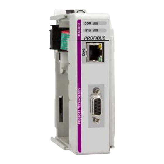
Page 16: About The Ilx69-Pbm
About the ILX69-PBM ILX69-PBM ♦ CompactLogix™ or MicroLogix™ Platform User Manual PROFIBUS Master Communication Module About the ILX69-PBM Device Drawing Page 16 of 113 ProSoft Technology, Inc. -
Page 17: Profibus Interface
ILX69-PBM ♦ CompactLogix™ or MicroLogix™ Platform About the ILX69-PBM PROFIBUS Master Communication Module User Manual PROFIBUS Interface PROFIBUS Interface (D-Sub female connector, 9 pin): Connection with D- Signal Description Sub female connector RxD / TxD-P Receive/Send Data-P, respectively connection B plug... - Page 18 User Manual PROFIBUS Master Communication Module If the ILX69-PBM is linked with only one other device on the bus, both devices must be connected to the ends of the bus line. These devices must deliver the supply voltage for the termination resistors. If three or more devices are connected to the bus, the ILX69- PBM can be connected at any desired position.
-
Page 19: Ethernet Interface
ILX69-PBM ♦ CompactLogix™ or MicroLogix™ Platform About the ILX69-PBM PROFIBUS Master Communication Module User Manual Ethernet Interface The Ethernet cable should contain an RJ45 connector. It should have a twisted pair cable of category 5 (CAT5) or higher, which consists of 4 twisted cores and has a maximum transmission rate of 100 MBit/s (CAT5). -
Page 20: Removable Memory Card
About the ILX69-PBM ILX69-PBM ♦ CompactLogix™ or MicroLogix™ Platform User Manual PROFIBUS Master Communication Module Removable Memory Card Memory Card Type SD card (HDSC format is not supported) Maximum storage capacity 4 GByte Required formatting FAT16 format (no FAT32) SD Card Connector SD Card Connector, e.g. -
Page 21: Installation
I/O bank power supply. Refer to the Compact 1769 Expansion I/O Power Supplies Installation Instructions. The ILX69-PBM has a distance rating of 2. Therefore, the module must be within 2 slots of the I/O bank’s power supply. Configuration and Network Communication ... -
Page 22: Software Installation
7 to install the configuration software ProSoft fdt Configuration Manager on your PC. Please visit www.prosoft-technology.com and download the ProSoft fdt Configuration Manager setup.exe file from the ILX69-PBM webpage. Double-click the ProSoft fdt Configuration Manager setup.exe. ® Select Yes at the Windows security question. - Page 23 ILX69-PBM ♦ CompactLogix™ or MicroLogix™ Platform Installation PROFIBUS Master Communication Module User Manual Click Install to continue the installation. The installation will take several minutes. ProSoft Technology, Inc. Page 23 of 113...
-
Page 24: Ilx69-Pbm Hardware Installation
ILX69-PBM. Electrostatically sensitive devices To prevent damage to the PLC and the ILX69-PBM, make sure that the ILX69-PBM is grounded via the backplane of the PLC. Also make sure you are discharged when you install/uninstall the ILX69-PBM. Device Destruction ... -
Page 25: Installing The Ilx69-Pbm Module
Move the ILX69-PBM back along the tongue-and-groove slots until the bus connectors line up with each other. Move the ILX69-PBM bus lever fully to the left until it clicks. Ensure it is locked firmly in place. Attach and lock an end cap terminator to the ILX69-PBM by using the tongue-and- groove slots as before. -
Page 26: Configuration And Start-Up
This chapter provides descriptions about the configuration and start-up of the ILX69- PBM. ILX69-PBM Configuration and Parameterization Steps: The configuration and parameterization of the ILX69-PBM is carried out in three steps: Configuration of the module in a CompactLogix™ project using the Studio 5000 or RSLogix 5000 programming tool. - Page 27 ILX69-PBM ♦ CompactLogix™ or MicroLogix™ Platform Configuration and Start-Up PROFIBUS Master Communication Module User Manual Select your controller T and R 16 or newer. EVISION Click OK. Right click on the I/O configuration > CompactBus Local of the controller project.
- Page 28 Configuration and Start-Up ILX69-PBM ♦ CompactLogix™ or MicroLogix™ Platform User Manual PROFIBUS Master Communication Module The following dialog box appears. Select "1769-MODULE Generic 1769 module" and click OK. The Module Properties dialog will open. Page 28 of 113 ProSoft Technology, Inc.
-
Page 29: Module Properties 1
Adjusting Input/Output Data Lengths in the Project 48. X = Number of Words configured for the ILX69-PBM (PROFIBUS input data); input size can be in the range between 44 and 248 words Y = Number of Words configured for the ILX69-PBM (PROFIBUS output data);... -
Page 30: Module Properties 2
Configuration and Start-Up ILX69-PBM ♦ CompactLogix™ or MicroLogix™ Platform User Manual PROFIBUS Master Communication Module Input Size – The input size must be at least 88 Bytes (44 Words). It must be large enough to accommodate the status information required by the module, which is 88 Bytes (44 Words) and the total number of PROFIBUS input data values from the slaves in the network. -
Page 31: Importing The Ladder Rung
ILX69-PBM ♦ CompactLogix™ or MicroLogix™ Platform Configuration and Start-Up PROFIBUS Master Communication Module User Manual 5.1.4 Importing the Ladder Rung In the Controller Organization window, expand the T folder and subfolder until ASKS you reach the M folder. ROGRAM In the M folder, double-click to open the M ladder. - Page 32 Configuration and Start-Up ILX69-PBM ♦ CompactLogix™ or MicroLogix™ Platform User Manual PROFIBUS Master Communication Module Navigate to the location on your PC where the .L5X Add-On Instruction (for example, My Documents or Desktop) is saved. Select I MPORT This action opens the Import Configuration dialog box, showing the controller tags that will be created.
- Page 33 ILX69-PBM ♦ CompactLogix™ or MicroLogix™ Platform Configuration and Start-Up PROFIBUS Master Communication Module User Manual Verify that the slot number is correct for the module in the Local:x tags. Click OK to confirm the import. When the import is completed, the new Add-On Instruction rung will appear in the ladder.
-
Page 34: Prosoft Fdt Configuration Manager
This section details the basics of using the ProSoft fdt Configuration Manager sofware to configure the ILX69-PBM and Slave I/O system. The configuration is downloaded via Ethernet to the module and stored into the Flash memory of the ILX69-PBM. 5.2.1 Creating a New ILX69-PBM Project Launch the ProSoft fdt Configuration Manager from the Windows Start menu. - Page 35 ILX69-PBM ♦ CompactLogix™ or MicroLogix™ Platform Configuration and Start-Up PROFIBUS Master Communication Module User Manual If needed, edit the N , and S . Then click OK. OCATION OLUTION The ILX69-PBM Network bus is displayed. ProSoft Technology, Inc. Page 35 of 113...
-
Page 36: Profibus Master Configuration
Configuration and Start-Up ILX69-PBM ♦ CompactLogix™ or MicroLogix™ Platform User Manual PROFIBUS Master Communication Module 5.2.2 PROFIBUS Master Configuration Double-click on the ILX69_PBM icon that appears in the Network View. In the navigation area on the left side of the Configuration dialog box, select B... -
Page 37: Profibus Slave Configuration
ILX69-PBM ♦ CompactLogix™ or MicroLogix™ Platform Configuration and Start-Up PROFIBUS Master Communication Module User Manual 5.2.3 PROFIBUS Slave Configuration The ProSoft fdt Configuration Manager comes pre-loaded with various PROFIBUS DPV0 and DPV1 slave GSD profiles. You can search them by F... - Page 38 Configuration and Start-Up ILX69-PBM ♦ CompactLogix™ or MicroLogix™ Platform User Manual PROFIBUS Master Communication Module Importing a GSD File Select the N tab at the top of the project window and click on I ETWORK MPORT EVICE ESCRIPTION The netDevice – Import Device Description dialog opens. Navigate to the GSD file location on your PC and click O Follow the steps to import the GSD file.
- Page 39 ILX69-PBM ♦ CompactLogix™ or MicroLogix™ Platform Configuration and Start-Up PROFIBUS Master Communication Module User Manual Adding a Slave to the Project In the ProSoft fdt Configuration Manager project screen, locate the slave in the slave catalog. Drag and drop the slave onto the magenta PROFIBUS network line.
- Page 40 Configuration and Start-Up ILX69-PBM ♦ CompactLogix™ or MicroLogix™ Platform User Manual PROFIBUS Master Communication Module Slave Settings Double-click on the slave icon in the Network view. A slave-specific configuration dialog box similar to the one shown below appears. Under C >...
- Page 41 PROFIBUS Master Communication Module User Manual Editing the Slave Address Assigning and editing a slave address is done in the ILX69-PBM configuration window. Double-click on the ILX69_PBM icon in the Network pane. This opens the netDevice – Configuration ILX69_PBM<x> window.
-
Page 42: Downloading The Project To The Ilx69-Pbm
PROFIBUS Master Communication Module Downloading the Project to the ILX69-PBM Once saved, the project is now ready to be downloaded to the ILX69-PBM. Make sure the ILX69-PBM is connected to the same Ethernet network as your PC. 5.3.1 Assigning an IP Address... - Page 43 PROFIBUS Master Communication Module User Manual Once found, the ILX69-PBM information appears in the Select the Device dialog. Click N >. Assign the IP address of the ILX69-PBM in the Set the Network Address dialog. ProSoft Technology, Inc. Page 43 of 113...
-
Page 44: Downloading The Project
When prompted, click OK when complete. 5.3.2 Downloading the Project Double-click on the D selection in the Solution Explorer pane. In EVICE SSIGNMENT the Device Assignment view, make sure the ILX69-PBM device is selected. Page 44 of 113 ProSoft Technology, Inc. - Page 45 ILX69-PBM ♦ CompactLogix™ or MicroLogix™ Platform Configuration and Start-Up PROFIBUS Master Communication Module User Manual Double-click on the N selection in the Solution Explorer pane to return to the ETWORK Network view. Right-click on the ILX69_PBM icon and select D .
- Page 46 Configuration and Start-Up ILX69-PBM ♦ CompactLogix™ or MicroLogix™ Platform User Manual PROFIBUS Master Communication Module PROFIBUS network communications are stopped during configuration download. When ready to download, click Y The configuration download begins. Page 46 of 113 ProSoft Technology, Inc.
- Page 47 The pane at the bottom of the window logs the project activity. The status of the download is shown here. With a successful download, the ILX69-PBM is now active on the PROFIBUS network with the new configuration. ProSoft Technology, Inc.
-
Page 48: Adjusting Input/Output Data Lengths In The Project
Configuration and Start-Up ILX69-PBM ♦ CompactLogix™ or MicroLogix™ Platform User Manual PROFIBUS Master Communication Module Adjusting Input/Output Data Lengths in the Project If you are using less than 408 bytes of input or 480 bytes of output data, the AOI can be adjusted to fit the needs of your PROFIBUS network. -
Page 49: Studio 5000 Adjustment (Optional)
PROFIBUS Master Communication Module User Manual 5.4.2 Studio 5000 Adjustment (Optional) This (optional) section allows you to tailor the ILX69-PBM input/output sizes to conserve memory space in the CompactLogix™ processor. Module Properties With the CompactLogix controller in Offline mode, double-click on the M ODULE in the I/O Configuration dialog to open the Module Properties. - Page 50 Configuration and Start-Up ILX69-PBM ♦ CompactLogix™ or MicroLogix™ Platform User Manual PROFIBUS Master Communication Module Add-On Instruction Definition Double-click on the AOIILX69PBM Add-On-Defined Data Type to open the Add-On Instruction Definition dialog. Under the Parameters tab, edit the Connection_Input Data Type size to the sum of PROFIBUS Input words + 44.
- Page 51 ILX69-PBM ♦ CompactLogix™ or MicroLogix™ Platform Configuration and Start-Up PROFIBUS Master Communication Module User Manual User-Defined Data Type Double-click on the EDIT_ILX69PBM_DATA User-Defined Data Type (UDT). Edit the SINT Data Type array size to match the number of inputs and outputs assigned to the slaves in the PROFIBUS network, as defined in the ProSoft fdt Configuration Manager.
-
Page 52: Copying And Moving A Project
Configuration and Start-Up ILX69-PBM ♦ CompactLogix™ or MicroLogix™ Platform User Manual PROFIBUS Master Communication Module Copying and Moving a Project The ProSoft fdt Configuration Manager software does not have a Save As option. This section explains how to copy and move a project. -
Page 53: Project Storage
TORE information, including GSD files. These are zipped together from the PC to the internal flash memory of the ILX69-PBM. This is allowed only if the user is logged in as Administrator (ProSoft fdt Configuration Manager User Access Control). The R function allows you to upload the project data to the PC. -
Page 54: Store Function
Via the Restore button, you can upload the project backup data from the internal flash memory from the ILX69-PBM to the PC. The project backup data can only be restored from the internal flash, not from an external SD memory card. -
Page 55: Project File Backup And Sd Card Handling
5.6.3 Project File Backup and SD Card Handling Using an SD memory card makes it possible to load the same configuration (plus firmware and Webpages) into multiple ILX69-PBM modules without using a PC. The memory card must be prepared by a PC beforehand. - Page 56 (valid) firmware or configuration database (NXD) file in the internal flash memory. Insert the prepared SD memory card into the SD card slot of the ILX69-PBM until it snaps in. Reconnect the power supply module to the network power.
-
Page 57: Start-Up Behavior With Or Without Sd Card
PROFIBUS Master Communication Module User Manual 5.6.4 Start-up Behavior with or without SD Card The start-up behavior of the ILX69-PBM depends on whether an SD memory card is inserted in the module or not. Start-up without Memory Card On power-up, the ILX69-PBM and the firmware are started and the configuration data is loaded from the CompactLogix processor using the Local:x:C.Data array into the ILX69-... -
Page 58: Startup.ini File
The user does not need to create this file. 5.6.6 Reset Device to Factory Settings with Memory Card Using a memory card that has the basic firmware stored on it, the ILX69-PBM can be restored back to factory settings. -
Page 59: Communication
PROFIBUS slaves is stored here. 6.1.2 PROFIBUS Network Output Data The PROFIBUS network output data is stored in the ILX69PBM.DATA.OUTPUT array. All outgoing data from the ILX69-PBM to be sent to the PROFIBUS slaves is to be placed here. ProSoft Technology, Inc. -
Page 60: I/O Communication And Memory Map
I/O data. 6.2.1 I/O Arrays Overview Input Array Below is a summary of the register layout of the input area of the ILX69-PBM. The offset values are defined in bytes. Offset... -
Page 61: Input Array
ILX69-PBM ♦ CompactLogix™ or MicroLogix™ Platform Communication PROFIBUS Master Communication Module User Manual Output Array Below is a summary of the register layout of the output area of the ILX69-PBM. The offset values are defined in bytes. Offset Register Type Name... - Page 62 A description of the option Controlled by Application can be found in the online help of the ILX69-PBM. Respectively in the ILX69-PBM manual, ProSoft fdt Configuration Manager for CompactLogix or ControlLogix Platform, PROFIBUS DP Master DTM in chapter Configuration in the section Master Setting > Start of Bus Communication.
- Page 63 ILX69-PBM ♦ CompactLogix™ or MicroLogix™ Platform Communication PROFIBUS Master Communication Module User Manual Generally, the module firmware is capable of transferring data blocks in a non- sequenced manner. Additionally, a single block transfer is possible. This is an example for 4 blocks:...
- Page 64 Reserved, set to 0 Using the handshake request bits, the user application can trigger different functions supported by the ILX69-PBM. Every handshake request bit (HsReq) has a corresponding handshake acknowledge bit (HsAck). It is located in the Device Status Register in the input array (see section Device Status Registers (page 61)).
- Page 65 Reserved for future use. Firmware Revision Bytes 4 to 7 contain the current Firmware Revision of the ILX69-PBM. The Minor revision is the low byte and the Major revision is the high byte. The mapping is shown in the table below.
- Page 66 Communication ILX69-PBM ♦ CompactLogix™ or MicroLogix™ Platform User Manual PROFIBUS Master Communication Module Block Counts Bytes 6 to 7 contain the Input and Output Block Counts of the ILX69-PBM. Byte Structure Data Type Description Offset Member Input Block Count SINT...
- Page 67 ILX69-PBM ♦ CompactLogix™ or MicroLogix™ Platform Communication PROFIBUS Master Communication Module User Manual GLOBAL-BITS Member Data Signification Meaning if Bit is set Offset Name Type Ctrl BOOL CONTROL-ERROR Parameterization error Aclr BOOL AUTO-CLEAR-ERROR Module stopped communication with all slaves and reached the auto-clear- end state.
- Page 68 Communication ILX69-PBM ♦ CompactLogix™ or MicroLogix™ Platform User Manual PROFIBUS Master Communication Module abSl_cfg[16] / Slave configuration area This variable is a field of 16 bytes and shows whether or not a certain slave station has been configured on the network. There is 1 bit for each slave. If set, the slave address has been configured.
- Page 69 Station Status_3 SINT See Definition Below Master Address SINT This byte contains the master address of the ILX69-PBM which has done the parameterization of the slave. If a slave is not parameterized, the value is 255. 78 to 79 Ident Number PROFIBUS Identification number from slave in which the diagnostics request was made.
- Page 70 Communication ILX69-PBM ♦ CompactLogix™ or MicroLogix™ Platform User Manual PROFIBUS Master Communication Module Slave Diag Failure This byte reflects the status of the Slave Diagnostics request. Error Significance Error Description Code source Service could be executed No error No error detected.
- Page 71 ILX69-PBM ♦ CompactLogix™ or MicroLogix™ Platform Communication PROFIBUS Master Communication Module User Manual Station Status_3 Slave device status information (continued) Member Data Description Offset Name Type 0 to 6 Reserved0..6 BOOL Reserved, set to 0 ExtDiagOverflow BOOL Slave has a large amount of diagnostics data and...
- Page 72 Note: It is possible to receive several alarms from one or more slave. The ILX69-PBM has a buffer for only 32 alarms. The application must respond as fast as possible to alarms.
-
Page 73: Output Array
Stop mode. RST – Reset Using this bit, the user program can reset (Cold boot) the ILX69-PBM. Important: Using the Reset command will cause an interruption in bus communication. All connected slaves will go to fail safe mode. - Page 74 Communication ILX69-PBM ♦ CompactLogix™ or MicroLogix™ Platform User Manual PROFIBUS Master Communication Module Handshake Acknowledge Bits Data Structure Description Offset Type Member BOOL HsAck0 SlvDiagCnf , Slave Diag Confirmation BOOL HsAck1 GlbCtrCnf , Global Control Confirmation BOOL HsAck2 Reserved, set to 0...
- Page 75 Address of the slave of which the diagnostics data are requested. Function If FNC is 0, the diagnostics data is requested from the internal buffer of the ILX69-PBM. This is the recommended method since the ILX69-PBM always has the most recent slave diagnostics data in its internal buffer.
- Page 76 Communication ILX69-PBM ♦ CompactLogix™ or MicroLogix™ Platform User Manual PROFIBUS Master Communication Module Global Control Registers Bytes 8 to 11 contain the Global Control Registers. A Global Control request makes it possible to send commands to single or multiple slaves. This request makes it possible to do Sync and Freeze functions.
- Page 77 ILX69-PBM ♦ CompactLogix™ or MicroLogix™ Platform Communication PROFIBUS Master Communication Module User Manual Group_Select The GS parameter allows the user program to select up to 8 possible slave groups to address by this service. This command is activated in the slave when the AND linkage between its internal Group_Ident and the desired Group_Select logic result is a '1'.
-
Page 78: Acyclic Messaging
Acyclic Messaging PROFIBUS DP acyclic services are supported by the Studio 5000 programming tool by means of CIP messages using the "MSG" instruction. The ILX69-PBM sample ladder and AOI include multiple PROFIBUS acyclic services such as read/write and slave diagnostic request. - Page 79 ILX69-PBM ♦ CompactLogix™ or MicroLogix™ Platform Communication PROFIBUS Master Communication Module User Manual Slave Diagnostic The Slave Diagnostic request is used to query the status of a slave by its address. This request can be used to determine the general health of the slave device. The instruction Request / Confirmation format is as follows.
- Page 80 Communication ILX69-PBM ♦ CompactLogix™ or MicroLogix™ Platform User Manual PROFIBUS Master Communication Module Name Data Type Description Reserved BOOL Reserved SlaveDeactivated BOOL Slave not active Reserved0...6 BOOL Reserved ExtendedDiagnostic BOOL Slave has a large amount of diagnostics data and cannot send...
-
Page 81: Dpv1 Messaging
DINT 0x2221 Command code 6.3.3 DPV1 Messaging This section describes DPV1 messaging functions supported by the ILX69-PBM. Important: Do not configure DPV1 services if your controller does not allow CIP messaging. DPV1 Read Command The MSG instruction format of a DPV1 read command and response is as follows. - Page 82 Communication ILX69-PBM ♦ CompactLogix™ or MicroLogix™ Platform User Manual PROFIBUS Master Communication Module ILX69PBM.CONTROL.DPV1.Read.Response Name Data Type Value Description .Status DINT 0x0000 ILX69-PBM Status .Command DINT 0x2211 Command code .SlaveAddres SINT 0 to 125 Slave address .SlotNumber SINT 0 to 255 Slot number .Index...
- Page 83 ILX69-PBM ♦ CompactLogix™ or MicroLogix™ Platform Communication PROFIBUS Master Communication Module User Manual DPV1 Alarm Response This message is used to send a DPV1 Alarm Response to a slave device. The message acknowledges the alarm when the appropriate indication appears in the DPV1 Alarm indication area.
-
Page 84: Cip Message Error Codes
Communication ILX69-PBM ♦ CompactLogix™ or MicroLogix™ Platform User Manual PROFIBUS Master Communication Module 6.3.4 CIP Message Error Codes This section includes error codes and conditions that can occur when using CIP messages. Your application can be constructed in a manner in which it catches the two possible error cases: ... - Page 85 ILX69-PBM ♦ CompactLogix™ or MicroLogix™ Platform Communication PROFIBUS Master Communication Module User Manual 15 hex 0000 hex Configuration data size Too much data Check if the overall length of too large transferred with the the requested command of CIP Message...
- Page 86 Communication ILX69-PBM ♦ CompactLogix™ or MicroLogix™ Platform User Manual PROFIBUS Master Communication Module DPV1 Read and Write Code Significance Error source Help 0 = CON_OK Service was executed without an error 2 = CON_RR Resource unavailable Slave Slave has no buffer space left for the...
- Page 87 ILX69-PBM ♦ CompactLogix™ or MicroLogix™ Platform Communication PROFIBUS Master Communication Module User Manual DPV1 Alarm Response Code Significance Error source Help 86 hex = REJ_INT The alarm handler Device No DPV1 capable device configured within is not initialized the module...
-
Page 88: Diagnostics And Troubleshooting
You can access the ILX69-PBM webpages for general device, diagnostics information, and firmware upgrades. Access to the Webpage Enter the IP address of the ILX69-PBM into an internet browser to access the homepage. Page 88 of 113 ProSoft Technology, Inc. -
Page 89: General Device And Diagnosis Information
Assigned MAC address of the device fixed by the manufacturer Address IP Address IP address of the ILX69-PBM that can be set via the ProSoft fdt Valid IP address Configuration Manager. The IP address must be unique. The IP address 0.0.0.0 indicates that no IP address has been configured yet. - Page 90 ILX69-PBM ♦ CompactLogix™ or MicroLogix™ Platform User Manual PROFIBUS Master Communication Module Module Status To display the ILX69-PBM status page, click FUNCTIONS > Module Status to access the device status and diagnostics information. Page 90 of 113 ProSoft Technology, Inc.
- Page 91 PBM are transmitted to the slave. Idle: Shows whether the ILX69-PBM is in IDLE state. Stop: Shows whether the ILX69-PBM is in STOP state, e.g. no cyclic data exchange is performed. The ILX69-PBM was stopped by the CompactLogix program or it changed to the STOP state because of a bus error.
- Page 92 Diagnostics and Troubleshooting ILX69-PBM ♦ CompactLogix™ or MicroLogix™ Platform User Manual PROFIBUS Master Communication Module Parameter Description Range of Value/Value No: Configuration is not locked General Diagnostics Communication Error Shows the communication error code. If the cause of the error is 0x00000000 to resolved, the value will be set to zero again.
- Page 93 ILX69-PBM ♦ CompactLogix™ or MicroLogix™ Platform Diagnostics and Troubleshooting PROFIBUS Master Communication Module User Manual Network Status To display the ILX69-PBM network status page, click FUNCTIONS > Network Status. This page contains network status and diagnostics information. ProSoft Technology, Inc. Page 93 of 113...
- Page 94 ‘Clear’: The ILX69-PBM reads the input information of the slaves and holds the outputs of the slaves in a safe condition. ‘Stop’: The ILX69-PBM is in a Stop state that means no data exchange takes place between the ILX69-PBM and the slaves.
-
Page 95: Firmware Update
ILX69-PBM ♦ CompactLogix™ or MicroLogix™ Platform Diagnostics and Troubleshooting PROFIBUS Master Communication Module User Manual 7.1.2 Firmware Update Click FUNCTIONS > Firmware Update to access the firmware update page. All fieldbus devices should be placed in a fail-safe condition under direct supervision before continuing. - Page 96 . The firmware file ONTINUE WITH PDATE prompt displays. Loading invalid or non-ProSoft Technology authorized firmware files could render your module unusable. Only proceed with a firmware update following instructions of ProSoft Technical Support. Page 96 of 113 ProSoft Technology, Inc.
- Page 97 ILX69-PBM ♦ CompactLogix™ or MicroLogix™ Platform Diagnostics and Troubleshooting PROFIBUS Master Communication Module User Manual … and enter ‘User name’ = ‘admin’ and ‘Password’ = ‘admin’ to the Click B ROWSE Authorization window, and then select the firmware file. Click Open. The name of the selected firmware file displays.
- Page 98 Diagnostics and Troubleshooting ILX69-PBM ♦ CompactLogix™ or MicroLogix™ Platform User Manual PROFIBUS Master Communication Module Click Update Firmware. If the firmware update fails, the page shows an error message: Firmware update error: Invalid device class. Page 98 of 113 ProSoft Technology, Inc.
- Page 99 ILX69-PBM ♦ CompactLogix™ or MicroLogix™ Platform Diagnostics and Troubleshooting PROFIBUS Master Communication Module User Manual If the firmware update is successful, a Firmware update OK message displays. To complete the update process, click R ESET EVICE Initiating a device reset causes the device reboot. A reboot will stop all communications immediately.
- Page 100 Diagnostics and Troubleshooting ILX69-PBM ♦ CompactLogix™ or MicroLogix™ Platform User Manual PROFIBUS Master Communication Module Check the P box. LEASE CONFIRM YOU WANT TO RESET THE DEVICE Click S UBMIT When complete, the following dialog will display: Page 100 of 113...
-
Page 101: Hardware Leds
ILX69-PBM ♦ CompactLogix™ or MicroLogix™ Platform Diagnostics and Troubleshooting PROFIBUS Master Communication Module User Manual Hardware LEDs The following section contains LED descriptions for the CompactLogix™ controller and the ILX69-PBM. 7.2.1 CompactLogix LEDs The CompactLogix™ PLC LEDs are described below. -
Page 102: Ilx69-Pbm Leds
User Manual PROFIBUS Master Communication Module 7.2.2 ILX69-PBM LEDs The ILX69-PBM LEDs indicate the status information. Each LED has a specific function during Run, configuration download, and error indications. Communication Status The ILX69-PBM PROFIBUS DP COM LED status is described below. - Page 103 ILX69-PBM ♦ CompactLogix™ or MicroLogix™ Platform Diagnostics and Troubleshooting PROFIBUS Master Communication Module User Manual Error Sources and Reasons This section describes the typical problems and sources of error that come up while commissioning the ILX69-PBM Behavior Significance Typical Reason Help CompactLogix™...
-
Page 104: Troubleshooting
100 RUN mode Troubleshooting Troubleshooting of the system is done by examining the LEDs on the front panel of the PLC and the LEDs on the front of the ILX69-PBM. The following can help with troubleshooting. LINK-LED Check the LINK LED status to see if a connection to the Ethernet is established. See section Ethernet Status (page 102). -
Page 105: Technical Data
ILX69-PBM ♦ CompactLogix™ or MicroLogix™ Platform Technical Data PROFIBUS Master Communication Module User Manual Technical Data Technical Data - ILX69-PBM Note: All technical data can be altered without notice. ILX69-PBM Parameter Value Description PROFIBUS DP master module General Function PROFIBUS DP master slot extension module for Rockwell CompactLogix™... - Page 106 For UL compliant usage: The device must be used in a pollution degree 2 environment. Device Dimensions (L x W x H) 131.6 x 92.1x 39.3 mm Mounting/Installation Rockwell backplane interface, refer to section ILX69-PBM Hardware Installation (page 24) RoHS Weight 152 g UL Certification...
-
Page 107: Technical Data - Profibus
ILX69-PBM ♦ CompactLogix™ or MicroLogix™ Platform Technical Data PROFIBUS Master Communication Module User Manual Environmental Specifications Environmental Measurements Value Specifications Type Emission Radiated Emission E-Field DIN EN 61131-2; CISPR 16, EN 55011 Conducted Emission DIN EN 61131-2; CISPR16, EN55011 Immunity Immunity to Electrostatic DIN EN 61131-2;... -
Page 108: Annex
The slaves must be able to process the Global Control message. With a Freeze command, the ILX69-PBM prompts a slave or a group of slaves to "freeze" their inputs to the current state. A Sync command causes the current output data to latch at their current state until the next Sync message arrives. -
Page 109: Dpv1 Services
Bit. When this bit is set, the communication between the ILX69-PBM and all slaves is stopped. All slaves will clear their outputs and the ILX69-PBM will be in stop mode. This control bit allows the user program to make a controlled start of the communication with the PROFIBUS network. -
Page 110: Disposal Of Electronic Equipment Waste
Annex ILX69-PBM ♦ CompactLogix™ or MicroLogix™ Platform User Manual PROFIBUS Master Communication Module Disposal of Electronic Equipment Waste As a consumer, you are legally obliged to dispose of all electronic equipment waste according to national and local regulations. Waste Electronic Equipment ... -
Page 111: Glossary
ILX69-PBM ♦ CompactLogix™ or MicroLogix™ Platform Annex PROFIBUS Master Communication Module User Manual Glossary Baud rate Data transmission speed of a communication channel or interface. Boot loader Program loading the firmware into the memory of a device in order to be executed. - Page 112 PROFIBUS Scanner PROFIBUS DP master module ProSoft fdt Configuration Manager FDT/DTM based configuration and diagnostics software by ProSoft Technology, Inc. RJ45 A connector type often used for Ethernet connection. It has been standardized by the Federal Communications Commission of the USA (FCC).
-
Page 113: Support, Service & Warranty
User Manual 10 Support, Service & Warranty 10.1 Contacting Technical Support ProSoft Technology, Inc. is committed to providing the most efficient and effective support possible. Before calling, please gather the following information to assist in expediting this process: Product Version Number...
Need help?
Do you have a question about the ILX69-PBM and is the answer not in the manual?
Questions and answers