
Subscribe to Our Youtube Channel
Related Manuals for ProSoft Technology ILX56-PBS


Summary of Contents for ProSoft Technology ILX56-PBS
- Page 1 ILX56-PBS PROFIBUS DPV1 Slave ® ControlLogix Platform February 8, 2024 User Manual...
-
Page 2: Your Feedback Please
Neither ProSoft Technology nor any of its affiliates or subsidiaries shall be responsible or liable for misuse of the information contained herein. Information in this document including illustrations, specifications and dimensions may contain technical inaccuracies or typographical errors. - Page 3 X: Indicates that this hazardous substance contained in at least one of the homogeneous materials used for this part is above the limit requirement in GB/T 26572. (企业可在此处,根据实际情况对上表中打“X”的技术原因进行进一步说明。) (According to actual situation, extra explanations can be given here for the technical reasons of items with "X".) ProSoft Technology, Inc. Page 3 of 86...
-
Page 4: Table Of Contents
ControlLogix® Platform User Manual Contents Your Feedback Please ......................2 Content Disclaimer ........................ 2 Preface Introduction to the ILX56-PBS ..............6 Features ....................... 7 Additional Information .................. 7 Installation Module Layout ..................... 8 PROFIBUS DP Port (RS485) ..............9 Setup Install Configuration Software .............. - Page 5 PROFIBUS Configuration ................71 8.2.2 Logix Configuration ..................71 Adding a PROFIBUS Slave ............... 72 Downloading the Configuration to the ILX56-PBS ........74 ControlLogix Configuration ................ 75 PROFIBUS Master Configuration .............. 77 Support, Service & Warranty Contacting Technical Support ..............86 Warranty Information .................
-
Page 6: Preface
This manual describes the installation, operation, and diagnostics of the ProSoft ILX56-PBS PROFIBUS DPV0/DPV1 Slave module. The ILX56-PBS slots into a 1756 ControlLogix backplane and allows the user to interface PROFIBUS DP to a ControlLogix controller via the ControlLogix backplane. -
Page 7: Features
PROFIBUS Slave (ILX56-PBS) The ILX56-PBS can also be configured to emulate up to 10 PROFIBUS slave devices. Each slave device emulated by the ILX56-PBS can be configured to provide DPV0 data exchange with a PROFIBUS Master on the network. -
Page 8: Installation
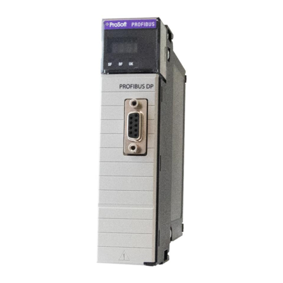
Installation Module Layout The ILX56-PBS has one RS485 PROFIBUS DP port at the front of the module. NOTE: All required power for the module is derived from the ControlLogix backplane. The module provides 3 diagnostic LEDs and a 4-character alpha-numeric LED display that provides the mode and status of the module. -
Page 9: Profibus Dp Port (Rs485)
PROFIBUS DP Port (RS485) The PROFIBUS DP port uses a female DB9 connector. This provides connection for the communication conductors, cable shielding and +5Vdc output power. Figure 2.3 – ILX56-PBS PROFIBUS DP (RS485) DB9 connector Table 2.2 – DB9 Connector layout Signal... -
Page 10: Setup
ILX56-PBS ♦ PROFIBUS DPV1 Master/Slave Setup ControlLogix® Platform User Manual Setup Install Configuration Software All the network setup and configuration of the module is achieved by means of the ProSoft PLX50 Configuration Utility. This software can be downloaded from: http://www.prosoft-technology.com. - Page 11 A new device can now be added by selecting Add under the Device menu. Figure 3.3 - Adding a new device In the Add New Device window select the ILX56-PBS and click the Ok button. Figure 3.4 – ILX56-PBS The device will appear in the Project Explorer tree as shown below, and its configuration window opened.
-
Page 12: Ilx56-Pbs Parameters
NOTE: Refer to the additional information section for documentation and installation links for ProSoft’s PLX50 Configuration Utility. 3.3.1 General The General configuration is shown in the following figure. The ILX56-PBS General configuration window is opened by either double-clicking on the module in the tree, or right-clicking the module and selecting Configuration. -
Page 13: Profibus - Slave Mode
The ILX56-PBS can operate in one of two modes: Quiet This mode allows the user to connect the ILX56-PBS to an active bus and run a DP packet capture. In this mode the ILX56-PBS will not communicate on the DP Bus, but rather only listen. - Page 14 ILX56-PBS ♦ PROFIBUS DPV1 Master/Slave Setup ControlLogix® Platform User Manual selected depending on the cable length, see chapter “PROFIBUS DP” ProSoft Technology, Inc. Page 14 of 86...
-
Page 15: Logix
Logix Base Tag A/B This is the tagname of the ILX56-PBS used for the input and output assembly. For example, if the module is in the local slot connected to a Logix controller the base Logix tag will be local:x (where x is the slot number). -
Page 16: Adding Profibus Dp Devices
User Manual Adding PROFIBUS DP Devices The user will need to add each PROFIBUS device to the ILX56-PBS. Each PROFIBUS device can then be configured. This is done by right-clicking on the PROFIBUS Devices item in the tree and selecting Add PROFIBUS Device. -
Page 17: General
ILX56-PBS ♦ PROFIBUS DPV1 Master/Slave Setup ControlLogix® Platform User Manual 3.4.1 General The General configuration is shown in the following figure. The Device General Configuration window is opened by either double-clicking on the slave device in the tree, or right-clicking the slave device and selecting Configuration. -
Page 18: Profibus Configuration
ILX56-PBS ♦ PROFIBUS DPV1 Master/Slave Setup ControlLogix® Platform User Manual 3.4.2 PROFIBUS Configuration The PROFIBUS configuration is shown in the following figure. The Device PROFIBUS configuration window is opened by either double-clicking on the slave device in the tree, or right-clicking the slave device and selecting Configuration. - Page 19 Watchdog Enable This parameter is only configured by the PROFIBUS Master. Enables the watchdog for the ILX56-PBS to monitor bus traffic. This ensures that the network master is still active, with process data still being updated. If the Watchdog timeout has been reached, the slave goes to its safe state (sets its outputs to "0").
-
Page 20: Dpv1
ILX56-PBS ♦ PROFIBUS DPV1 Master/Slave Setup ControlLogix® Platform User Manual 3.4.3 DPV1 The DPV1 configuration is shown in the following figure. The slave device DPV1 configuration window is opened by either double-clicking on the slave device in the tree, or right-clicking the slave device and selecting Configuration. -
Page 21: User Parameters
▪ Diagnostic Alarm ▪ Manufacturer Alarm ▪ Status Alarm ▪ Update Alarm 3.4.4 User Parameters The User Parameters tab is not used for the ILX56-PBS. Figure 3.17 – Device User Parameter configuration parameters ProSoft Technology, Inc. Page 21 of 86... -
Page 22: Slot Configuration
ILX56-PBS ♦ PROFIBUS DPV1 Master/Slave Setup ControlLogix® Platform User Manual 3.4.5 Slot Configuration The PROFIBUS Input/Output Module can be added in Slot Configuration tab. Slot data point selectable sizes are as follows: 1, 2, 4, 8 and 16 byte. Modular Input/Output Slave supports up to 16 modules. - Page 23 ILX56-PBS ♦ PROFIBUS DPV1 Master/Slave Setup ControlLogix® Platform User Manual When the module is emulating the legacy device, the Module Selection will appear as follows: Figure 3.20 – Module Selection (legacy device) ProSoft Technology, Inc. Page 23 of 86...
-
Page 24: Start-Up Parameters
Setup ControlLogix® Platform User Manual 3.4.6 Start-up Parameters The Start-up Parameters tab is not used for the ILX56-PBS. Figure 3.21 – Device Start-up Parameters 3.4.7 DPV1 Objects The DPV1 Objects configuration is shown in the following figure. The slave device DPV1 Objects configuration window is opened by either double-clicking on the slave device in the tree, or right-clicking the slave device and selecting Configuration. -
Page 25: Dpv1 Alarms
The Logix Tagname from where the alarm data will be read. (Logix Only) NOTE: The PROFIBUS DP Master connected to the ILX56-PBS will be able to configure the following alarms: Diagnostic Alarm, Process Alarm, Pull Plug Alarm, Status Alarm, Update Alarm, and Manufacturer Specific Alarm. -
Page 26: Module Download
User Manual Module Download Once the ILX56-PBS configuration has been completed, it must be downloaded to the module. The configured IP address of the Logix Controller or the 1756 Ethernet card will be used to connect to the module, as set in the “Connection Path”. -
Page 27: Studio 5000 Configuration
Profile (AOP). 3.6.1 Installing the Add-On Profile (AOP) The user will first need to install the ILX56-PBS AOP before the module can be added to the Logix I/O tree. Download the AOP from www.prosoft-technology.com. Once downloaded, extract the zip file and run the MPSetup.exe file. - Page 28 The module configuration dialog will open, specify the Name and Slot to complete the instantiation. Figure 3.30 – Module instantiation Once the instantiation is complete, the ILX56-PBS module will appear in the Logix IO tree. Figure 3.31 – Logix IO tree The Module Defined Data Types will automatically be created during the instantiation process.
-
Page 29: Plx50 Configuration Utility Project File
User Manual 3.6.3 PLX50 Configuration Utility Project File The ILX56-PBS AOP allows the user to save the PLX50 Configuration Utility project file in the AOP, as well as launch the PLX50 Configuration Utility from the AOP. Figure 3.32 – AOP - PLX50 Configuration Utility When no PLX50 Configuration Utility project has been defined, the user can Browse for an existing PLX50 Configuration Utility project. -
Page 30: Generating A Logix .L5X File
3.7.1 Local Rack Module Location If the ILX56-PBS is in the same local rack as the Logix controller owning it, the Logix Base Tag will be Local:xx (where xx is the slot number of the module). Below is an example where the ILX56-PBS is in slot 1 of the local rack. -
Page 31: Remote Rack Module Location
ILX56-PBS ♦ PROFIBUS DPV1 Master/Slave Setup ControlLogix® Platform User Manual 3.7.2 Remote Rack Module Location If the module is in a remote rack, the user will need to enter the Logix Base Tag based on the name of the remote rack (see the example below): Figure 3.36 –... -
Page 32: Generating The L5X File
ControlLogix® Platform User Manual 3.7.3 Generating the L5X File In the PLX50 Configuration Utility, right-click on the ILX56-PBS item in the tree and select Generate Logix L5X. Figure 3.38 – Selecting Generate Logix L5X The user will then be prompted to select a suitable file name and path for the L5X file. - Page 33 ILX56-PBS ♦ PROFIBUS DPV1 Master/Slave Setup ControlLogix® Platform User Manual This L5X file can now be imported into the Studio 5000 project by right-clicking on a suitable Program and selecting Add, and then Import Routine. Figure 3.40 – Importing the L5X file into Studio 5000 In the file open dialog, select the newly-created L5X file and click OK.
- Page 34 ILX56-PBS ♦ PROFIBUS DPV1 Master/Slave Setup ControlLogix® Platform User Manual Figure 3.42 – Imported Logix Objects Tags are created for each emulated slave device. The structure of which comprises the following: • Input Status - Status related to slave device Input Data –...
- Page 35 ILX56-PBS ♦ PROFIBUS DPV1 Master/Slave Setup ControlLogix® Platform User Manual Figure 3.43 – Slave Device-Specific tag ProSoft Technology, Inc. Page 35 of 86...
-
Page 36: Sd Card
ControlLogix® Platform User Manual SD Card The ILX56-PBS supports an SD Card that can be used for disaster recovery. It can be pre-loaded with the required firmware and/or application configuration. Figure 3.44 – Module Bottom View – SD Card Slot Important: The user will need to ensure that the SD Card has been formatted for FAT32. -
Page 37: Configuration
ILX56-PBS ♦ PROFIBUS DPV1 Master/Slave Setup ControlLogix® Platform User Manual 3.10 Configuration The user can add the PLX50CU configuration file to the SD Card root directory in one of two ways. Figure 3.46 – SD Card – Configuration file 3.10.1 Manual Copy... - Page 38 ILX56-PBS ♦ PROFIBUS DPV1 Master/Slave Setup ControlLogix® Platform User Manual Figure 3.48 – Configuration Export for SD Card Important: The filename of the configuration file must not be changed. Important: If more than one configuration file, with different configuration signatures, of the same product is on the SD Card, only the last configuration will be used.
-
Page 39: Plx50 Configuration Utility Upload
ILX56-PBS ♦ PROFIBUS DPV1 Master/Slave Setup ControlLogix® Platform User Manual 3.10.2 PLX50 Configuration Utility Upload When the SD Card has been inserted into the module, the user has the option to directly upload the configuration onto the SD Card using the Save Configuration to SD Card option in PLX50CU. -
Page 40: Operation
1 – ILX56-PBS has been successfully configured. 0 – ILX56-PBS is not configured. Owned Indicates if the ILX56-PBS is owned by a Logix Controller with a connection count similar to what has been configured in PLX50CU. 1 – ILX56-PBS is connected. - Page 41 This tag was designed for ILX56-PBM to decipher between ILX56-PBM in master mode or slave mode. 1 – The ILX56-PBS will always have this bit on. 0 – The ILX56-PBS should never be in state where this bit is 0. ControllerRun The connected Logix controller is in RUN mode.
-
Page 42: General Control
User Manual General Control The emulated ILX56-PBS slave devices will be enabled by setting the correct enable bit in the Logix output assembly. Once the respective bit has been set in the DeviceEnable array, the ILX56-PBS will become active on the PROFIBUS network and will start responding to a PROFIBUS DP Master. -
Page 43: Status And Dpv0 Data Exchange
The DPV0 data is exchanged with Logix using the Class 1 Logix connection. The device-specific tag contains all the input and output data fields, as well as important control and status information. Figure 4.3 – ILX56-PBS Slave Device-Specific tag Table 4.4 – Device Input tags Description... - Page 44 ILX56-PBS ♦ PROFIBUS DPV1 Master/Slave Operation ControlLogix® Platform User Manual This Error flag is transient and will clear once a valid response is received. AlarmPending Indicates the device has an alarm pending on the local PROFIBUS network. When the specific bit is set ‘1’ then the device has an alarm pending that must be unloaded and when the bit is off ‘0’...
-
Page 45: Dpv1 Class 1 Messaging (Ms1)
(from 0 to 1) the AlarmTrigger tag as shown below: Figure 4.5 – ILX56-PBS Slave Alarm Trigger Once the alarm has been triggered, the ILX56-PBS will read the alarm data from the Logix tag and add it to the PROFIBUS diagnostics (which will then be read by the PROFIBUS Master). - Page 46 ControlLogix® Platform User Manual Figure 4.6 – ILX56-PBS Alarm Acknowledge NOTE: An alarm will only be triggered when the AlarmTrigger tag is toggled from 0 to 1. The format of the DPV1 Alarm data in the Logix SINT array is shown below:...
- Page 47 ILX56-PBS ♦ PROFIBUS DPV1 Master/Slave Operation ControlLogix® Platform User Manual An example of the Alarm Data is shown below: Figure 4.7 –DPV1 Alarm Data Example ProSoft Technology, Inc. Page 47 of 86...
-
Page 48: Firmware Upgrade
ILX56-PBS ♦ PROFIBUS DPV1 Master/Slave Operation ControlLogix® Platform User Manual Firmware Upgrade The PLX50 Configuration Utility allows the user to upgrade the module firmware in the field. In the PLX50 Configuration Utility, go to the Tool menu and select the DeviceFlash option. - Page 49 Once firmware upgrade is complete, the Device Flash tool will provide the details of the updated module. Figure 4.11 – ILX56-PBS successfully updated Important: The ILX56-PBS firmware is digitally signed so the user will only be able to flash the ILX56- PBS with authorized firmware. ProSoft Technology, Inc.
-
Page 50: Diagnostics
ControlLogix® Platform User Manual Diagnostics LEDs The ILX56-PBS provides 3 diagnostic LEDs and a 4-character alpha-numeric LED display for diagnostics purposes. Figure 5.1 - ILX56-PBS LEDs The ILX56-PBS LEDs indicate the module status as follows: Table 5.1 – ILX56-PBS Module LED operation Description Off –... - Page 51 Duplicate Station A PROFIBUS station with a duplicate node has been detected. No Config Loaded No configuration has been loaded onto the ILX56-PBS. The module LED display will also show the instance name of the module configured in PLX50CU. ProSoft Technology, Inc.
-
Page 52: Module Status Monitoring
Configuration Utility. To view the module’s status in the PLX50 Configuration Utility environment, the ILX56-PBS must be online. If the module is not already online (following a recent configuration download), then right-click on the module and select the Go Online option. -
Page 53: Ilx56-Pbs Status
ControlLogix® Platform User Manual 5.2.1 ILX56-PBS Status The Status monitoring window of the ILX56-PBS can be opened by either double- clicking on the Status item in the Project Explorer tree, or by right-clicking on the module and selecting Status. Figure 5.4 - Selecting ILX56-PBS online Status... - Page 54 This is the mode of operation of the module. Quiet This mode allows the user to connect the ILX56-PBS to an active bus and run a DP packet capture. In this mode the ILX56-PBS will not communicate on the DP Bus but rather only listen.
-
Page 55: Slave Status
ControlLogix® Platform User Manual Slave Status The Slave mode diagnostics tab displays the following parameters: Figure 5.6 – ILX56-PBS Status monitoring – Slave Status Table 5.4 - Parameters displayed in the Status Monitoring – Slave Status Tab Description Parameter BAUD Rate... -
Page 56: Logix Statistics
ILX56-PBS ♦ PROFIBUS DPV1 Master/Slave Diagnostics ControlLogix® Platform User Manual Logix Statistics The Logix statistics are the statistics for connections and messages from the ILX56- PBS to the Logix Controller. These are used when DPV1 messaging and alarming are mapped to Logix tags. -
Page 57: Ilx56-Pbs Emulated Slave Device Status
5.2.2 ILX56-PBS Emulated Slave Device Status The Status monitoring window of each PROFIBUS slave device connected to the ILX56-PBS can be opened by right-clicking on the specific slave device in the PLX50 Configuration Utility tree, and selecting Status. Figure 5.8 - Selecting slave device online Status The device status window contains multiple tabs to display the current status of the specific slave device. -
Page 58: Profibus Packet Capture
ControlLogix® Platform User Manual PROFIBUS Packet Capture The ILX56-PBS provides the capability to capture the PROFIBUS traffic for analysis. To invoke the capture, double-click on the module in the Project Explorer tree, or right-clicking the module and selecting DP Packet Capture. - Page 59 ILX56-PBS ♦ PROFIBUS DPV1 Master/Slave Diagnostics ControlLogix® Platform User Manual Example PROFIBUS capture: Figure 5.11 - PROFIBUS Packet Capture complete The captured PROFIBUS packets are tabulated as follows: Table 5.6 - PROFIBUS Packet Capture fields Description Statistic Index The packet index incremented for each packet sent or received.
-
Page 60: Packet Details
ILX56-PBS ♦ PROFIBUS DPV1 Master/Slave Diagnostics ControlLogix® Platform User Manual 5.3.1 Packet Details Additional detail about specific packets can be viewed by either double-clicking or right-clicking on the packet and selecting the Show Detail option. Figure 5.12 - PROFIBUS Packet Capture - Show Detail A Packet Window will display the details of the selected packet. -
Page 61: Packet Filter
ILX56-PBS ♦ PROFIBUS DPV1 Master/Slave Diagnostics ControlLogix® Platform User Manual 5.3.2 Packet Filter The packet filter can be used to hide certain packet types. To open the packet filter, click on the Filter icon in the toolbar. Figure 5.14 - PROFIBUS Packet Filter Figure 5.15 - PROFIBUS Packet Filter Options... -
Page 62: Saving Packet Filter Options
ILX56-PBS ♦ PROFIBUS DPV1 Master/Slave Diagnostics ControlLogix® Platform User Manual 5.3.3 Saving Packet Filter Options The selected Filter options can also be saved and re-opened for future use. Figure 5.16 - PROFIBUS Packet Filter Options – Save / Open The packet capture can be saved to a file for further analysis, by selecting the Save button on the toolbar. -
Page 63: Module Event Log
ControlLogix® Platform User Manual Module Event Log The ILX56-PBS module logs various diagnostic records to an internal event log. These logs are stored in non-volatile memory and can be displayed using the PLX50 Configuration Utility. To view the logs, select the Event Viewer option in the Project Explorer tree. -
Page 64: Technical Specifications
ILX56-PBS ♦ PROFIBUS DPV1 Master/Slave Technical Specifications ControlLogix® Platform User Manual Technical Specifications Electrical Table 6.1 - Electrical specification Rating Specification Backplane Current Load 450 mA @ 5 VDC 2 mA @ 24 VDC Enclosure rating IP20, NEMA/UL Open Type Temperature -20 to 70 °C... -
Page 65: Profibus Dp
ILX56-PBS ♦ PROFIBUS DPV1 Master/Slave PROFIBUS DP ControlLogix® Platform User Manual PROFIBUS DP Introduction PROFIBUS is a vendor-independent, open Fieldbus standard for a wide range of applications in manufacturing, process and building automation. Vendor independence and openness are guaranteed by the PROFIBUS standard EN 50 170. -
Page 66: Profibus Fms
ILX56-PBS ♦ PROFIBUS DPV1 Master/Slave PROFIBUS DP ControlLogix® Platform User Manual 7.1.3 PROFIBUS FMS PROFIBUS FMS is the general-purpose solution for communication tasks at the cell level. Powerful FMS services open up a wide range of applications and provide great flexibility. -
Page 67: Acyclic Communication
ILX56-PBS ♦ PROFIBUS DPV1 Master/Slave PROFIBUS DP ControlLogix® Platform User Manual Acyclic communication In addition to the cyclic data exchange, the PROFIBUS protocol has the option of acyclic communication. This service is not configured. There are 2 different communication channels possible between the requested master and the slave: •... -
Page 68: Profibus Dp Connector Description
ILX56-PBS ♦ PROFIBUS DPV1 Master/Slave PROFIBUS DP ControlLogix® Platform User Manual PROFIBUS DP connector description Table 9.4 – PROFIBUS DP connector DB9 Pin# DB9 Termination with ILX56-PBS DB9 Pin Description Chassis ground Reserved Data+ / B In case of termination connect this pin to Pin 8... -
Page 69: Ilx56-Pbs Quickstart
ILX56-PBS Quickstart ControlLogix® Platform User Manual ILX56-PBS Quickstart This chapter covers the configuration of the ILX56-PBS to communicate with a Siemens CPU 315-2PN/DP PROFIBUS Master using the Siemens TIA Portal v15 software. GSD File Management Tool Installation Download the ProSoft PLX50 Configuration Utility from http://www.prosoft-... -
Page 70: Creating A New Project
Device menu. Figure 8.3 – Adding a new device In the Add New Device window, select the ILX56-PBS and click the Ok button. Figure 8.4 – Adding a new ILX56-PBS device The device will appear in the Project Explorer tree with its configuration window opened. -
Page 71: Profibus Configuration
Figure 8.5 – Profibus tab 8.2.2 Logix Configuration Under the Logix tab, configure the Logix Connections and Logix Base Tag A to reflect ILX56-PBS position in ControlLogix Rack. Click Apply and then the Ok button. Figure 8.6 – Logix tab ProSoft Technology, Inc. -
Page 72: Adding A Profibus Slave
User Manual Adding a PROFIBUS Slave You will need to add each PROFIBUS device to the ILX56-PBS project tree, depending on how many PROFIBUS slaves you need to emulate (up to 10). In this example, 1 slave PROFIBUS slave will be added and configured. - Page 73 ILX56-PBS ♦ PROFIBUS DPV1 Master/Slave ILX56-PBS Quickstart ControlLogix® Platform User Manual Add the appropriate modules and click the Ok button. Figure 8.10 – Added modules The ILX56-PBS is now configured in the ProSoft PLX50 Configuration Utility. ProSoft Technology, Inc. Page 73 of 86...
-
Page 74: Downloading The Configuration To The Ilx56-Pbs
Click on the Browse button to launch the target browser. Navigate to the module, and press Ok. Figure 8.12 – Connection Path Download device configuration by right-clicking on the ILX56-PBS icon and selecting Download. Figure 8.13 – Downloading the device configuration Upon successful download, the PLX50 Configuration Utility device configuration is now complete. -
Page 75: Controllogix Configuration
ControlLogix Configuration Generate the required Logix and UDTs in the PLX50 Configuration Utility by right- clicking on the ILX56-PBS icon and selecting Generate Logix L5X. Figure 8.14 – Generate Logix L5X option Select a suitable file name and path for the L5X file, then click the Save button. - Page 76 Main Routine. Figure 8.17 – Imported mapping routine To enable the ILX56-PBS PROFIBUS slave, place a value of ‘1’ in the appropriate slave ID Controller Tag(s) Local:1:O1.DeviceEnable.SlaveID_xxx. Figure 8.18 – Setting the value of the slave ID Controller Tag ProSoft Technology, Inc.
-
Page 77: Profibus Master Configuration
ILX56-PBS ♦ PROFIBUS DPV1 Master/Slave ILX56-PBS Quickstart ControlLogix® Platform User Manual PROFIBUS Master Configuration The Siemens 315-2PN/DP Processor will be used as a PROFIBUS Master to the ILX56-PBS slave. Open the Total Integrated Automation Portal V15 software and create a new project. - Page 78 ILX56-PBS Quickstart ControlLogix® Platform User Manual Add the ILX56-PBS GSD by selecting Option at the menu bar then selecting Manage general station description files (GSD) Figure 8.21 – Manage general station description files *In this example, ILX56-PBS GSD has already been installed in this computer but this may not be the case for new users.
- Page 79 Figure 8.23 – Configuring the MP/DP interface Add ILX56-PBS as PROFIBUS slave by choosing ILX56-PBS in the catalog list from the right and dragging the ILX56-PBS module in the Network window. Figure 8.24 – Adding the ILX56-PBS as PROFIBUS slave ProSoft Technology, Inc.
- Page 80 Connect the two purple box icons to assign the PLC_1 CPU 315-2PN/DP PROFIBUS Master to Slave_1 ILX56-PBS PROFIBUS Slave. Figure 8.25 – Connecting the purple box icons Double click on Slave_1 ILX56-PBS icon to configure the input/output bytes of ILX56-PBS. Figure 8.26 – Configuring the input/output bytes ProSoft Technology, Inc.
- Page 81 ILX56-PBS ♦ PROFIBUS DPV1 Master/Slave ILX56-PBS Quickstart ControlLogix® Platform User Manual 10 Change the address of I address and Q address if so desire. Figure 8.27 – Changing the I address and Q address 11 Add Watch Table to modify the output and monitor the input. Add desired QB and IB address to modify and monitor.
- Page 82 ILX56-PBS ♦ PROFIBUS DPV1 Master/Slave ILX56-PBS Quickstart ControlLogix® Platform User Manual 12 Compile and download the TIA V15 file to the 315-2PN/DP CPU. Figure 8.29 – Compiling the TIA V15 file Figure 8.30 – Downloading the TIA V15 file ProSoft Technology, Inc.
- Page 83 ILX56-PBS ♦ PROFIBUS DPV1 Master/Slave ILX56-PBS Quickstart ControlLogix® Platform User Manual 13 Click the Load button. Figure 8.31 – Load preview 14 Click the Finish button. Figure 8.32 – Load results ProSoft Technology, Inc. Page 83 of 86...
- Page 84 ILX56-PBS ♦ PROFIBUS DPV1 Master/Slave ILX56-PBS Quickstart ControlLogix® Platform User Manual 15 Go Online with the Siemens processor. Figure 8.33 – Going online with the Siemens processor 16 To modify and monitor the PROFIBUS Output/Input data, open the Watch table and click the Monitor All button.
- Page 85 ILX56-PBS Quickstart ControlLogix® Platform User Manual 18 To verify the data was sent and received by the ILX56-PBS, Open Studio 5000 and check the appropriate Controller Tags while being online with the Rockwell Processor. Figure 8.36 – Checking the Controller Tags 19 To monitor the PROFIBUS Input data, enter values in the appropriate Controller Tags in Studio 5000 while being online with Rockwell Processor.
-
Page 86: Support, Service & Warranty
ControlLogix® Platform User Manual Support, Service & Warranty Contacting Technical Support ProSoft Technology, Inc. is committed to providing the most efficient and effective support possible. Before calling, please gather the following information to assist in expediting this process: • Product Version Number •...
Need help?
Do you have a question about the ILX56-PBS and is the answer not in the manual?
Questions and answers