
Related Manuals for Fronius Robacta Reamer Alu Edition


Summary of Contents for Fronius Robacta Reamer Alu Edition
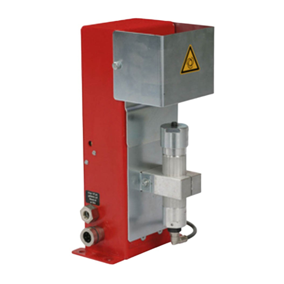
- Page 1 Operating Instructions Robacta Reamer Alu Edition Robacta Reamer Alu 3000upm Robacta Reamer Twin Operating Instructions 42,0426,0146,EN 018-01062022...
-
Page 3: Table Of Contents
Application areas Illustration of the various device types Scope of supply and options General Robacta Reamer Alu Edition scope of supply Robacta Reamer Alu Edition options Robacta Reamer Alu 3000upm scope of supply Robacta Reamer Alu 3000upm options Robacta Reamer Twin scope of supply... - Page 4 Welding torch cleaning position - Robacta Reamer Alu 3000upm Welding torch cleaning position - Robacta Reamer Twin Adjusting the gas nozzle clamping device on the Robacta Reamer Alu Edition and Robacta Reamer Alu 3000upm Adjusting the gas nozzle clamping device...
- Page 5 Technical data Robacta Reamer Alu Edition and Robacta Reamer Alu 3000upm Robacta Reamer Twin Appendix Circuit diagram Robacta Reamer, Robacta Reamer Alu Edition, Robacta Reamer Alu Edition 3000rpm Circuit diagram Robacta Reamer Twin Robacta Reamer Twin pneumatic diagram Declarations of Conformity...
-
Page 6: Safety Rules
Safety rules Explanation of DANGER! safety notices Indicates immediate danger. ▶ If not avoided, death or serious injury will result. WARNING! Indicates a potentially hazardous situation. ▶ If not avoided, death or serious injury may result. CAUTION! Indicates a situation where damage or injury could occur. ▶... -
Page 7: Proper Use
Proper use The device is to be used exclusively for its intended purpose. The device is intended solely for the mechanical cleaning of Fronius robot weld- ing torches in automatic mode. Any use above and beyond this purpose is deemed improper. The manufacturer shall not be held liable for any damage arising from such usage. -
Page 8: Protecting Yourself And Others
Stay out of the working area of the robot. The device must be incorporated into a higher-level safety system within a se- cured area. If this area has to be accessed when setup and maintenance work is carried out, make sure that the entire system is switched off for the duration of the work in this area and that it is prevented from starting up accidentally, e.g. -
Page 9: Emc Measures
Devices in emission class B: Satisfy the emissions criteria for residential and industrial areas. This is also true for residential areas in which the energy is supplied from the public low- voltage mains. EMC device classification as per the rating plate or technical data. EMC measures In certain cases, even though a device complies with the standard limit values for emissions, it may affect the application area for which it was designed (e.g. -
Page 10: Safety Measures In Normal Operation
After transporting the device, it must be visually inspected for damage before commissioning. Any damage must be repaired by trained service technicians be- fore commissioning the device. Safety measures Only operate the device if all safety devices are fully functional. If the safety in normal opera- devices are not fully functional, there is a risk of tion... -
Page 11: Disposal
Further details on safety inspection and calibration can be obtained from your service centre. They will provide you on request with any documents you may re- quire. Disposal Waste electrical and electronic equipment must be collected separately and re- cycled in an environmentally-friendly way, in accordance with the European Dir- ective and national legislation. -
Page 13: General
General... -
Page 15: General
During the cleaning process, both wire electrodes are shortened to a defined length for the next welding process. The wire cutter is an optional extra with the Robacta Reamer Alu Edition and Robacta Reamer Alu 3000upm. For professional installation, a stable fitting base is available for all devices. -
Page 16: Illustration Of The Various Device Types
Illustration of the various device types Robacta Reamer Alu Edition, Robacta Reamer Alu 3000upm, Robacta Reamer Twin... -
Page 17: Scope Of Supply And Options
Alu Edition scope of supply The cleaning brush and adapter for the cleaning brush are not included in the scope of supply. Robacta Reamer Alu Edition cleaning device Spatter tray retainer Spatter tray Tightening key for cleaning mo- Compressed air relief valve... -
Page 18: Robacta Reamer Alu 3000Upm Scope Of Supply
Robacta Reamer NOTE! Alu 3000upm The cleaning cutter and adapter for scope of supply the cleaning cutter are not included in the scope of supply. Robacta Reamer Alu 3000upm cleaning device Spatter tray retainer Spatter tray Tightening key for cleaning mo- Compressed air relief valve not shown: Harting Han6P connecting plug (X1) without cable... -
Page 19: Robacta Reamer Twin Options
Filling funnel for parting agent Fixings for assembling the cleaning device: 4 screws 4 washers 4 lock washers 4 nuts Robacta Reamer Fitting base Twin options Cleaning cutter adjustment aid Parting agent - spray unit... -
Page 20: Warning Notices On The Device
The warning notices and rating plate must not be removed or painted over. The locations of the warning notices are shown on the Robacta Reamer Twin as an example. On the Robacta Reamer Alu Edition and Robacta Reamer Alu 3000upm the warning notices are in the same location. - Page 21 Do not use the functions described here until you have thoroughly read and understood the following documents: these operating instructions all the operating instructions for the system components, es- pecially the safety rules For indoor use only Wear eye protection Notice warning of automatic start-up of the device...
-
Page 22: Transport
Transport Transport The device is to be transported by the following devices: devices On pallets using a forklift truck On pallets using a lift truck Manual WARNING! Danger from machines and objects falling. This can result in serious injury and damage to property. ▶... -
Page 23: Controls, Connections And Mechanical Components
Controls, connections and mechan- ical components... -
Page 25: Safety
Safety Safety Observe the following safety instructions for all work described in the "Control elements, connections and mechanical components" section. WARNING! Operating the equipment incorrectly can cause serious injury and damage. The functions described must only be used by trained and qualified personnel. Do not use the functions described here until you have thoroughly read and un- derstood the following documents: ▶... -
Page 26: Control Elements, Connections And Mechanical Components Of The Robacta Reamer Alu Edi
Control elements, connections and mechanical components of the Robacta Reamer Alu Edition and Robacta Reamer Alu 3000upm Control ele- ments, connec- tions and mech- anical compon- ents Side view Front view Compressed air connection for a dry compressed air supply at 6 bar (86.99 psi) Thread identification compressed air connection: G ¼“... -
Page 27: Robacta Reamer Twin Control Elements, Connections And Mechanical Components
Robacta Reamer Twin control elements, connec- tions and mechanical components Control ele- ments, connec- tions and mech- anical compon- ents Parting agent adjuster for setting the spray amount on the parting agent spray nozzles Compressed air connection for a dry compressed air supply at 6 bar (86.99 psi) Thread identification compressed air connection: G ¼“... - Page 28 (10) (10) ( ( 1 1 1 1 ) ) 1 1 1 1 ) ) Wire cutter valve lever activates the wire cutter (10) Wire cutter (11) Parting agent spray nozzles sprays the parting agent into the interior and onto the front of the gas nozzles using compressed air...
-
Page 29: Harting Han6P Connecting Plug Pin Assignment (X1) For Robot Control
Harting Han6P connecting plug pin assignment (X1) for robot control General CAUTION! Danger from overcurrent. Damage to the Harting Han6P connection supply may result. ▶ Secure the power supply of the cleaning device against overcurrent with a 500 mA slow-blow fuse. NOTE! To avoid malfunction, keep the cable length between the cleaning device and ro- bot control as short as possible. -
Page 31: Installation And Commissioning
Installation and commissioning... -
Page 33: Safety
Safety Safety Observe the following safety rules for all work described in the "Installation and start-up" section. WARNING! Incorrect operation or shoddy workmanship can cause serious injury or damage. All activities described in these operating instructions may only be carried out by trained and qualified personnel. -
Page 34: Ensuring That The Cleaning Device Is Depressurised
Ensure that the cleaning device has been disconnected from the compressed air supply On the Robacta Reamer Alu Edition, Robacta Reamer Alu 3000upm: Briefly turn the "Cleaning" screw on the cleaning device 90° to the right, then turn it straight back to its original position... - Page 35 If the cleaning device wire cutter does not respond to the movement of the valve lever, the cleaning device (including the wire cutter) is depressurised If the wire cutter responds to the movement of the valve lever, the cleaning device (and therefore also the wire cutter) is still connected to a compressed air supply.
-
Page 36: Before Commissioning
Before commissioning Proper use The cleaning device is to be used exclusively for cleaning Fronius robot welding torches, especially the gas nozzle and its interior, in automatic mode and within the scope of the technical data. Any use above and beyond this purpose is deemed improper. -
Page 37: Measures For The Safe Operation Of The Device With Untrained Personnel
Measures for the If untrained operators have access to the device, its compressed air supply must safe operation of be disconnected for the duration of work in accordance with 'Performance Level the device with d' of the ISO 13849-1 standard. untrained per- sonnel To ensure that the compressed air supply is interrupted as required, MS6-SV... -
Page 38: Screwing The Cleaning Device To The Underlying Surface
Screwing the cleaning device to the underlying surface Screwing the WARNING! cleaning device and installation Danger from machines falling or toppling over. stand to the un- This can result in serious injury and damage to property. ▶ derlying surface Always secure the installation stand to the underlying surface. ▶... -
Page 39: Screwing The Cleaning Device To The Underlying Surface
Attach the spatter tray retainer as shown Screwing the WARNING! cleaning device to the underlying Danger from machines falling or toppling over. surface This can result in serious injury and damage to property. ▶ Always secure the cleaning device to the underlying surface. ▶... - Page 40 Attach the spatter tray retainer as shown...
-
Page 41: Torch Cleaning Position
Torch cleaning position Welding torch cleaning position - Robacta Ream- er Alu Edition Welding torch cleaning position - Robacta Ream- er Alu 3000upm Welding torch NOTE! cleaning position - Robacta Ream- Ensure that the coolant lines on the er Twin gas nozzle cannot be damaged by the extending/retracting gas nozzle clamping device. -
Page 42: Adjusting The Gas Nozzle Clamping Device On The Robacta Reamer Alu Edition And Robacta
Adjusting the gas nozzle clamping device on the Robacta Reamer Alu Edition and Robacta Reamer Alu 3000upm Adjusting the NOTE! gas nozzle The gas nozzle clamping device must be adjusted so that no bearing pressure is clamping device transferred to the robot. -
Page 43: Fitting The Cleaning Brush On The Robacta Reamer Alu Edition
Fitting the cleaning brush on the Robacta Reamer Alu Edition Fitting the CAUTION! cleaning brush A cleaning brush that has become very hot through use can cause severe burns. Before handling the cleaning brush, allow cleaning brush to cool to room temper- ature (+25°C, +77 °F). -
Page 44: Fitting The Cleaning Cutter On The Robacta Reamer Alu 3000Upm
Fitting the cleaning cutter on the Robacta Ream- er Alu 3000upm Fitting the CAUTION! cleaning cutter A cleaning cutter that has become very hot through use can cause severe burns. Before handling cleaning cutters, allow cleaning cutter to cool to room temperat- ure (+25°C, +77 °F). -
Page 45: Fitting The Cleaning Cutter On The Robacta Reamer Twin
Fitting the cleaning cutter on the Robacta Ream- er Twin Fitting the CAUTION! cleaning cutter Danger due to cleaning cutter that has become very hot through use. This can result in severe burns. ▶ Before handling cleaning cutters, allow cleaning cutter to cool to room tem- perature (+25 °C, +77 °F). -
Page 46: Adjusting The Robacta Reamer Alu Edition Lifting Device
Adjusting the Robacta Reamer Alu Edition lifting device Adjusting the Remove protective covering (1) lifting device Ensure that the lifting device is in its lowest position Loosen screw (2) on the lifting device Move the welding torch to the cleaning position... -
Page 47: Adjusting The Robacta Reamer Alu 3000Upm Lifting Device
Adjusting the Robacta Reamer Alu 3000upm lift- ing device Adjusting the Remove protective covering (1) lifting device Remove gas nozzle from torch neck Ensure that the lifting device is in its lowest position Loosen screw (2) on the lifting device Move the welding torch to the cleaning position Push the lifting device (3) by hand... -
Page 48: Adjusting The Robacta Reamer Twin Lifting Device
Adjusting the Robacta Reamer Twin lifting device Adjusting the It is recommended that one of the following adjustment aids is used to adjust the lifting device lifting device: Robacta Twin 900 adjustment aid, item no. 42,0001,5560 An adjustment aid is not necessary when the gas nozzle is open, as the welding torch is clamped above the gas nozzle. -
Page 49: Starting Up The Robacta Reamer Twin Parting Agent Nebuliser
Starting up the Robacta Reamer Twin parting agent nebuliser Starting up the NOTE! parting agent nebuliser Only use "Robacta Reamer" parting agent (item number 42,0411,8042). The composition of this parting agent is designed specifically for the cleaning device. If other manufacturers' products are used, trouble-free operation cannot be guaranteed. - Page 50 Correct adjust- NOTE! ment of the part- Both spray jets of parting agent must ing agent spray nozzles on the meet in front of the gas nozzle, so that Robacta Reamer they fully enter the nozzle. Twin...
-
Page 51: Installing Mechanically-Controlled Wire Cutter On The Robacta Reamer Alu Edition And
Reamer Alu 3000upm (optional) Installing the NOTE! mechanically- Installation of the wire cutter is shown for the Robacta Reamer Alu Edition. controlled wire cutter The wire cutter is installed in exactly the same way on the Robacta Reamer Alu 3000upm. - Page 52 Remove screw (5) Undo screws and washers (6) (6) (6) Keep the screws and washers for future use Screw the wire cutter to the clean- ing device using the previously re- moved screws and washers (6)
- Page 53 Cut through the compressed air hose (7) in the interior of the clean- ing device housing in the position shown Detach compressed air connection (8) from compressed air connec- tion (9)
- Page 54 Attach the wire cutter compressed air connection (9) to compressed air connection (8) on the cleaning device housing, as shown Insert the compressed air hose (10) firmly into the compressed air distributor (11) Insert the two loose ends (12) and (13) of the previously cut com- pressed air hose firmly into the compressed air distributor (11) as...
-
Page 55: Installing The Electrically-Controlled Wire Cutter On The Robacta Reamer Alu Edition And
Reamer Alu 3000upm (optional) Installing the NOTE! electrically-con- Installation of the wire cutter is shown for the Robacta Reamer Alu Edition. trolled wire cut- The wire cutter is installed in exactly the same way on the Robacta Reamer Alu 3000upm. - Page 56 Undo screws and washers (5) (5) (5) Keep the screws and washers for future use Screw the wire cutter to the clean- ing device using the previously re- moved screws and washers (5) as shown Fit the cleaning device housing cover (4) to the cleaning device in its original position NOTE!
-
Page 57: Wire Cutter Function
Wire cutter function Maximum wire Wire electrodes with a diameter of up to 1.6 mm (0.063 in.) can be cut with an diameter electrically or mechanically-controlled wire cutter. Two wire electrodes with a diameter of up to 1.6 mm (0.063 in.) can be cut in the case of twin applications. -
Page 58: Installing The Compressed Air Supply
Installing the compressed air supply Establishing the To establish the compressed air supply: compressed air Depressurise the compressed air supply line of the cleaning device and en- supply for the sure that it remains depressurised for the duration of the following work on cleaning device, the device function of the... -
Page 59: Starting Up The Cleaning Device
If present, the cleaning device installation stand is bolted to underlying sur- face Cleaning device is bolted to underlying surface Only on the Robacta Reamer Alu Edition and Robacta Reamer Alu 3000upm: gas nozzle clamping device is adjusted Cleaning cutter / cleaning brush has been fitted... -
Page 60: Programme Sequence And Signal Waveform On The Robacta Reamer Alu Edition And Robacta
Programme sequence and signal waveform on the Robacta Reamer Alu Edition and Robacta Reamer Alu 3000upm Cleaning pro- CAUTION! gramme se- quence Risk of damage. Do not start in automated mode until the cleaning device has been properly in- stalled and started up. - Page 61 Start from position A Pos. A - approx. 50 mm (1.97 in.) above centre of cleaning motor - Speed: high speed mode Query output (Gas nozzle free output sig- Query = Low nal) (Gas nozzle clamped) - Low or High Query = High Stop (Gas nozzle free)
-
Page 62: Signal Waveform
Query output (Gas nozzle free output sig- Query = Low nal) (Gas nozzle clamped) - Low or High Query = High Stop (Gas nozzle free) Start from position A Pos. A - approx. 50 mm (1.97 in.) above centre of cleaning device - Speed: 10 cm/s (236.22 ipm) Signal waveform... -
Page 63: Robacta Reamer Twin Programme Sequence And Signal Waveform
Robacta Reamer Twin programme sequence and signal waveform Cleaning pro- CAUTION! gramme se- quence Risk of damage. Do not start in automated mode until the cleaning device has been properly in- stalled and started up. NOTE! Not coating the interior of the welding torch may result in permanent soiling of the torch when welding begins. - Page 64 Start from position C Pos. C - approx. 50 mm (1.97 in.) above centre of cleaning device - Speed: high speed mode Query output (Gas nozzle free output sig- Query = Low nal) (Gas nozzle clamped) - Low or High Query = High Reset (Gas nozzle free)
- Page 65 Cleaning procedure Input "Begin cleaning" Gas nozzle clamping device clamps the gas nozzle Cleaning cutter cleans the first side of the welding torch for approx. 3 sec. Cleaning motor moves to the starting position Gas nozzle clamping device opens for approx. 0.5 sec. to allow the cleaning motor to move to the second side of the welding torch Gas nozzle clamping device clamps the gas nozzle again Cleaning cutter cleans the second side of the welding torch for approx.
-
Page 66: Signal Waveform
Start from position C Pos. C - approx. 50 mm (1.97 in.) above centre of cleaning device - Speed: 10 cm/s (236.22 ipm) Signal waveform Meaning Input "Begin cleaning" Output "Gas nozzle released" Gas nozzle released (Cleaning, page 1) Gas nozzle released (Cleaning, page 2) Cleaning time: 7.0 - 7.5 seconds... -
Page 67: Care, Maintenance And Disposal
Care, maintenance and disposal... -
Page 69: Safety
Safety Safety Observe the following safety rules for all work described in the "Care, mainten- ance and disposal" section. WARNING! Incorrect operation or shoddy workmanship can cause serious injury or damage. All activities described in these operating instructions may only be carried out by trained and qualified personnel. -
Page 70: Ensuring That The Cleaning Device Is Depressurised
Ensure that the cleaning device has been disconnected from the compressed air supply On the Robacta Reamer Alu Edition, Robacta Reamer Alu 3000upm: Briefly turn the "Cleaning" screw on the cleaning device 90° to the right, then turn it straight back to its original position... - Page 71 On the Robacta Reamer Twin: Briefly press the valve lever on the cleaning device wire cutter to the side by more than 15° using a tool If the cleaning device wire cutter does not respond to the movement of the valve lever, the cleaning device (including the wire cutter) is depressurised If the wire cutter responds to the movement of the valve lever, the cleaning device (and therefore also the wire cutter) is still connected to a compressed...
-
Page 72: Care, Maintenance And Disposal
Care, maintenance and disposal General The cleaning device generally needs no maintenance. However, to keep the clean- ing device in good working condition for years to come, several points on care and maintenance must be observed. Before each Only Robacta Reamer Twin: Check fill level in parting agent container and start-up top up if necessary Check the cleaning cutter / cleaning brushes for wear and replace if neces-... -
Page 73: Troubleshooting
Troubleshooting... -
Page 75: Safety
Safety Safety Observe the following safety rules for all work described in the "Troubleshooting" section. WARNING! Incorrect operation or shoddy workmanship can cause serious injury or damage. All activities described in these operating instructions may only be carried out by trained and qualified personnel. -
Page 76: Ensuring That The Cleaning Device Is Depressurised
Ensure that the cleaning device has been disconnected from the compressed air supply On the Robacta Reamer Alu Edition, Robacta Reamer Alu 3000upm: Briefly turn the "Cleaning" screw on the cleaning device 90° to the right, then turn it straight back to its original position... - Page 77 On the Robacta Reamer Twin: Briefly press the valve lever on the cleaning device wire cutter to the side by more than 15° using a tool If the cleaning device wire cutter does not respond to the movement of the valve lever, the cleaning device (including the wire cutter) is depressurised If the wire cutter responds to the movement of the valve lever, the cleaning device (and therefore also the wire cutter) is still connected to a compressed...
-
Page 78: Troubleshooting
Troubleshooting Errors in pro- Parting agent does not spray (Robacta Reamer Twin only) gram sequence Parting agent container is full Cause: Not enough spray Remedy: Adjust spray amount Cause: Parting agent spray nozzles are blocked Remedy: Clean parting agent spray nozzles If cleaning does not rectify problem, contact After-Sales Service - replace parting agent spray nozzles Cause:... - Page 79 Cleaning motor does not work Cause: Compressed air relief valve closed Remedy: Open compressed air relief valve Cause: No signal from robot Remedy: Check connection to robot control Cause: Mechanical fault on cleaning motor Remedy: Contact After-Sales Service - replace cleaning motor...
-
Page 81: Technical Data
Technical data... -
Page 83: Technical Data
Technical data Robacta Reamer Supply voltage + 24 V DC Alu Edition and Nominal output 3.2 W Robacta Reamer Alu 3000upm Nominal pressure 6 bar 86.99 psi Air consumption 420 l/min 443.81 qt./min Thread identification compressed air connec- G ¼“ tion Harting Han6P (X1) Input: + 24 V DC / max. - Page 84 Max. noise emission (LWA) 82 dB (A) Dimensions l x w x h 325 x 220 x 350 mm 12.80 x 8.66 x 13.78 in. Weight 17 kg (without parting agent and optional wire cut- 37.48 lb. ter)
-
Page 85: Appendix
Appendix... -
Page 87: Circuit Diagram Robacta Reamer, Robacta Reamer Alu Edition, Robacta Reamer Alu Edition
Circuit diagram Robacta Reamer, Robacta Ream- er Alu Edition, Robacta Reamer Alu Edition 3000rpm... -
Page 88: Circuit Diagram Robacta Reamer Twin
Circuit diagram Robacta Reamer Twin input start cleaning GND 0VDC +24V output gas nozzle free - BLUE - - BROWN - - BLACK - - BLUE - - BROWN - - BLACK - - BLUE - - BROWN - - BLACK -... -
Page 89: Robacta Reamer Twin Pneumatic Diagram
Robacta Reamer Twin pneumatic diagram... -
Page 90: Declarations Of Conformity
(technische Dokumentation) (technical documents) (technique documentation) Ing. Josef Feichtinger Ing. Josef Feichtinger Ing. Josef Feichtinger Günter Fronius Straße 1 Günter Fronius Straße 1 Günter Fronius Straße 1 A - 4600 Wels-Thalheim A - 4600 Wels-Thalheim A - 4600 Wels-Thalheim 2016 ppa. - Page 91 (technische Dokumentation) (technical documents) (technique documentation) Ing. Josef Feichtinger Ing. Josef Feichtinger Ing. Josef Feichtinger Günter Fronius Straße 1 Günter Fronius Straße 1 Günter Fronius Straße 1 A - 4600 Wels-Thalheim A - 4600 Wels-Thalheim A - 4600 Wels-Thalheim 2016 ppa.
- Page 92 SPAREPARTS ONLINE Fronius International GmbH Froniusstraße 1 4643 Pettenbach Austria contact@fronius.com www.fronius.com Under www.fronius.com/contact you will find the adresses of all Fronius Sales & Service Partners and locations.
Need help?
Do you have a question about the Robacta Reamer Alu Edition and is the answer not in the manual?
Questions and answers