Table of Contents
Advertisement
Quick Links
/ Perfect Charging /
Perfect Welding
Robacta Reamer Alu Edition
Robacta Reamer Alu 3000upm
Robacta Reamer Twin
42,0426,0146,EN 015-04042019
Fronius prints on elemental chlorine free paper (ECF) sourced from certified sustainable forests (FSC).
/ Solar Energy
Operating Instructions
Spare parts list
Welding torch cleaning
Advertisement
Table of Contents
Troubleshooting

Related Manuals for Fronius Robacta Reamer Alu Edition


Summary of Contents for Fronius Robacta Reamer Alu Edition
- Page 1 Perfect Welding / Solar Energy Operating Instructions Robacta Reamer Alu Edition Spare parts list Robacta Reamer Alu 3000upm Welding torch cleaning Robacta Reamer Twin 42,0426,0146,EN 015-04042019 Fronius prints on elemental chlorine free paper (ECF) sourced from certified sustainable forests (FSC).
- Page 3 Thank you for the trust you have placed in our company and congratulations on buying this high-quality Fronius product. These instructions will help you familiarise yourself with the product. Reading the instructions carefully will enable you to learn about the many different features it has to offer.
-
Page 5: Table Of Contents
Controls, connections and mechanical components Safety................................. Safety..............................Control elements, connections and mechanical components of the Robacta Reamer Alu Edition and Ro- bacta Reamer Alu 3000upm ........................Control elements, connections and mechanical components............... Robacta Reamer Twin control elements, connections and mechanical components ........ - Page 6 Welding torch cleaning position - Robacta Reamer Alu 3000upm............Welding torch cleaning position - Robacta Reamer Twin ..............Adjusting the gas nozzle clamping device on the Robacta Reamer Alu Edition and Robacta Reamer Alu 3000upm ..............................Adjusting the gas nozzle clamping device ....................
- Page 7 Spare parts list: Robacta Reamer Alu 3000upm..................Spare parts list: Robacta Reamer Twin ..................... Spare parts list: Robacta Reamer Twin ..................... Circuit diagrams: Robacta Reamer Alu Edition / Robacta Reamer Alu 3000upm ........Circuit diagrams: Robacta Reamer Twin ....................Robacta Reamer Twin pneumatic diagram....................
-
Page 9: Safety Rules
Proper use The device is to be used exclusively for its intended purpose. The device is intended solely for the mechanical cleaning of Fronius robot welding torches in automatic mode. Any use above and beyond this purpose is deemed improper. The manufacturer shall not be held liable for any damage arising from such usage. -
Page 10: Obligations Of The Operator
Relative humidity: up to 50 % at 40 °C (104 °F) up to 90 % at 20 °C (68 °F) Keep ambient air free from dust, acids, corrosive gases and substances, etc. Can be used at altitudes of up to 2000 m (6500 ft) Obligations of the The operator must only allow persons to work with the device who: operator... -
Page 11: Protecting Yourself And Others
Covers may only be opened/removed for the duration of any maintenance, installation or repair work. During operation Ensure that all covers are closed and fitted properly Keep all covers closed Protecting your- When welding, you expose yourself to numerous dangers. In addition to these operating self and others instructions, the safety rules of the manufacturer of the entire welding system must also be observed. -
Page 12: Emf Measures
EMF measures Electromagnetic fields may pose as yet unknown risks to health: effects on the health of others in the vicinity, e.g. wearers of pacemakers and hearing aids wearers of pacemakers must seek advice from their doctor before approaching the de- vice or any welding that is in progress for safety reasons, keep distances between the welding cables and the welder's head/ torso as large as possible... -
Page 13: Commissioning, Maintenance And Repair
Commissioning, It is impossible to guarantee that bought-in parts are designed and manufactured to meet maintenance and the demands made of them, or that they satisfy safety requirements. repair Use only original spare and wearing parts (also applies to standard parts). Do not carry out any modifications, alterations, etc. -
Page 15: General
General... -
Page 17: General
During the cleaning process, both wire electrodes are shortened to a defined length for the next welding process. The wire cutter is an optional extra with the Robacta Reamer Alu Edition and Robacta Reamer Alu 3000upm. For professional installation, a stable fitting base is available for all devices. -
Page 18: Scope Of Supply And Options
NOTE! of supply The cleaning brush and adapter for the cleaning brush are not included in the scope of supply. Robacta Reamer Alu Edition clea- ning device Spatter tray retainer Spatter tray Tightening key for cleaning motor Compressed air relief valve... -
Page 19: Robacta Reamer Alu 3000Upm Scope Of Supply
Robacta Reamer Alu 3000upm NOTE! scope of supply The cleaning cutter and adapter for the cleaning cutter are not included in the scope of supply. Robacta Reamer Alu 3000upm cle- aning device Spatter tray retainer Spatter tray Tightening key for cleaning motor Compressed air relief valve not shown: Harting Han6P connecting plug (X1) without cable... -
Page 20: Robacta Reamer Twin Options
Filling funnel for parting agent Fixings for assembling the cleaning device: 4 screws 4 washers 4 lock washers 4 nuts Robacta Reamer Fitting base Twin options Cleaning cutter adjustment aid Parting agent - spray unit... -
Page 21: Warning Notices On The Device
The warning notices and rating plate must not be removed or painted over. The locations of the warning notices are shown on the Robacta Reamer Twin as an exam- ple. On the Robacta Reamer Alu Edition and Robacta Reamer Alu 3000upm the warning notices are in the same location. - Page 22 WARNING! Risk of serious injury from: mechanically powered parts compressed air/parting agent mixture escaping from the parting agent spray nozzles flying parts (shavings, etc.) Keep device free from current and pressure during maintenance and servic- ing. Do not use the functions described here until you have thoroughly read and understood the following documents: these operating instructions all the operating instructions for the system components, especially the...
-
Page 23: Transport
Transport Vehicles The device is to be transported by the following vehicles: on pallets using a counterbalanced lift truck on pallets using a lift truck manually WARNING! Equipment that falls or topples over can cause serious or even fatal injury. ►... -
Page 25: Controls, Connections And Mechanical Components
Controls, connections and mechani- cal components... -
Page 27: Safety
Safety Safety Observe the following safety instructions for all work described in the "Control elements, connections and mechanical components" section. WARNING! Operating the equipment incorrectly can cause serious injury and damage. The functions described must only be used by trained and qualified personnel. Do not use the functions described here until you have thoroughly read and understood the following documents: ►... -
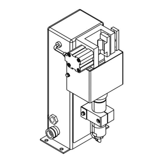
Page 28: Control Elements, Connections And Mechanical Components Of The Robacta Reamer Alu Edition And Robacta Reamer Alu 3000Upm
Control elements, connections and mechanical components of the Robacta Reamer Alu Edition and Robacta Reamer Alu 3000upm Control elements, connections and mechanical com- ponents Side view Front view Function Compressed air connection for a dry compressed air supply at 6 bar (86.99 psi) -
Page 29: Robacta Reamer Twin Control Elements, Connections And Mechanical Components
Robacta Reamer Twin control elements, connec- tions and mechanical components Control elements, connections and mechanical com- ponents Function Parting agent adjuster for setting the spray amount on the parting agent spray nozzles Compressed air connection for a dry compressed air supply at 6 bar (86.99 psi) Harting Han6P connection socket (X1) for a + 24 V DC supply CAUTION! - Page 30 (10) (10) ( ( 1 1 1 1 ) ) 1 1 1 1 ) ) Function Wire cutter valve lever activates the wire cutter (10) Wire cutter (11) Parting agent spray nozzles sprays the parting agent into the interior and onto the front of the gas nozzles using compressed air...
-
Page 31: Harting Han6P Connecting Plug Pin Assignment (X1) For Robot Control
Harting Han6P connecting plug pin assignment (X1) for robot control General CAUTION! Risk of damage to Harting Han6P connection (X1) supply due to overcurrent. Secure supply against overcurrent with a 500 mA slow-blow fuse. NOTE! To avoid malfunction, keep the cable length between the cleaning device and robot control as short as possible. -
Page 33: Installation And Commissioning
Installation and commissioning... -
Page 35: Safety
Safety Safety Observe the following safety rules for all work described in the "Installation and start-up" section. WARNING! Incorrect operation or shoddy workmanship can cause serious injury or damage. All activities described in these operating instructions may only be carried out by trained and qualified personnel. -
Page 36: Ensuring That The Cleaning Device Is Depressurised
Ensure that the cleaning device has been disconnected from the compressed air sup- On the Robacta Reamer Alu Edition, Robacta Reamer Alu 3000upm: Briefly turn the "Cleaning" screw on the cleaning device 90° to the right, then turn it... -
Page 37: Before Commissioning
Before commissioning Proper use The cleaning device is to be used exclusively for cleaning Fronius robot welding torches, especially the gas nozzle and its interior, in automatic mode and within the scope of the technical data. Any use above and beyond this purpose is deemed improper. The manu- facturer shall not be held liable for any damage arising from such usage. -
Page 38: Screwing The Cleaning Device To The Underlying Surface
Screwing the cleaning device to the underlying sur- face Screwing the NOTE! cleaning device and installation Different fixings may be required to set up the installation stand depending on the stand to the un- type of underlying surface (foundation). derlying surface Fixings are therefore not included in the scope of supply of the installation stand. - Page 39 NOTE! Place the cleaning device and the spatter tray retainer on a level, firm and vibration- free surface (foundation). Position the cleaning device in such a way that the distance the robot has to travel to the cleaning position is as short as possible.
-
Page 40: Torch Cleaning Position
Torch cleaning position Welding torch cleaning position - Robacta Reamer Alu Edition Welding torch cleaning position - Robacta Reamer Alu 3000upm Welding torch cleaning position NOTE! - Robacta Reamer Twin Ensure that the coolant lines on the gas nozzle cannot be damaged by the exten- ding/retracting gas nozzle clamping de- vice. -
Page 41: Adjusting The Gas Nozzle Clamping Device On The Robacta Reamer Alu Edition And Robacta Reamer Alu 3000Upm
Adjusting the gas nozzle clamping device on the Ro- bacta Reamer Alu Edition and Robacta Reamer Alu 3000upm Adjusting the gas NOTE! nozzle clamping device The gas nozzle clamping device must be adjusted so that no bearing pressure is transferred to the robot. The gas nozzle must only be clamped onto the cylindrical surface. -
Page 42: Fitting The Cleaning Brush On The Robacta Reamer Alu Edition
Fitting the cleaning brush on the Robacta Reamer Alu Edition Fitting the clean- CAUTION! ing brush A cleaning brush that has become very hot through use can cause severe burns. Before handling the cleaning brush, allow cleaning brush to cool to room temperature (+25°C, +77 °F). -
Page 43: Fitting The Cleaning Cutter On The Robacta Reamer Alu 3000Upm
Fitting the cleaning cutter on the Robacta Reamer Alu 3000upm Fitting the clean- CAUTION! ing cutter A cleaning cutter that has become very hot through use can cause severe burns. Before handling cleaning cutters, allow cleaning cutter to cool to room temperature (+25°C, +77 °F). -
Page 44: Fitting The Cleaning Cutter On The Robacta Reamer Twin
Fitting the cleaning cutter on the Robacta Reamer Twin Fitting the clean- CAUTION! ing cutter A cleaning cutter that has become very hot through use can cause severe burns. Before handling cleaning cutters, allow cleaning cutter to cool to room temperature (+25°C, +77 °F). -
Page 45: Adjusting The Robacta Reamer Alu Edition Lifting Device
Adjusting the Robacta Reamer Alu Edition lifting de- vice Adjusting the lift- Remove protective covering (1) ing device Ensure that the lifting device is in its lo- west position Loosen screw (2) on the lifting device Move the welding torch to the cleaning... -
Page 46: Adjusting The Robacta Reamer Alu 3000Upm Lifting Device
Adjusting the Robacta Reamer Alu 3000upm lifting device Adjusting the lift- Remove protective covering (1) ing device Remove gas nozzle from torch neck Ensure that the lifting device is in its lo- west position Loosen screw (2) on the lifting device Move the welding torch to the cleaning position Push the lifting device (3) by hand into... -
Page 47: Adjusting The Robacta Reamer Twin Lifting Device
Adjusting the Robacta Reamer Twin lifting device Adjusting the lift- It is recommended that one of the following adjustment aids is used to adjust the lifting de- ing device vice: Robacta Twin 900 adjustment aid, item no. 42,0001,5560 Remove protective covering (1) Ensure that the lifting device is in its lo- west position Loosen screw (2) on the lifting device... -
Page 48: Starting Up The Robacta Reamer Twin Parting Agent Nebuliser
Starting up the Robacta Reamer Twin parting agent nebuliser Starting up the NOTE! parting agent nebuliser Only use "Robacta Reamer" parting agent (item number 42,0411,8042). The composition of this parting agent is designed specifically for the cleaning device. If oth- er manufacturers' products are used, trouble-free operation cannot be guaranteed. -
Page 49: Correct Adjustment Of The Parting Agent Spray Nozzles On The Robacta Reamer Twin
Correct adjust- ment of the part- NOTE! ing agent spray nozzles on the Both spray jets of parting agent must Robacta Reamer meet in front of the gas nozzle, so that Twin they fully enter the nozzle. -
Page 50: Installing Mechanically-Controlled Wire Cutter On The Robacta Reamer Alu Edition And Robacta Reamer Alu 3000Upm (Optional)
NOTE! chanically-con- trolled wire cutter Installation of the wire cutter is shown for the Robacta Reamer Alu Edition. The wire cutter is installed in exactly the same way on the Robacta Reamer Alu 3000upm. Position the mounting bracket (1) on... - Page 51 Remove screw (5) Undo screws and washers (6) (6) (6) Keep the screws and washers for future use Screw the wire cutter to the cleaning device using the previously removed screws and washers (6)
- Page 52 Cut through the compressed air hose (7) in the interior of the cleaning device housing in the position shown Detach compressed air connection (8) from compressed air connection (9)
- Page 53 Attach the wire cutter compressed air connection (9) to compressed air connection (8) on the cleaning device housing, as shown Insert the compressed air hose (10) firmly into the compressed air distribu- tor (11) Insert the two loose ends (12) and (13) of the previously cut compressed air hose firmly into the compressed air dis- tributor (11) as shown...
-
Page 54: Installing The Electrically-Controlled Wire Cutter On The Robacta Reamer Alu Edition And Robacta Reamer Alu 3000Upm (Optional)
NOTE! electrically-con- trolled wire cutter Installation of the wire cutter is shown for the Robacta Reamer Alu Edition. The wire cutter is installed in exactly the same way on the Robacta Reamer Alu 3000upm. Position the mounting bracket (1) on... - Page 55 Undo screws and washers (5) (5) (5) Keep the screws and washers for future use Screw the wire cutter to the cleaning device using the previously removed screws and washers (5) as shown Fit the cleaning device housing cover (4) to the cleaning device in its original position NOTE! The wire cutter must be supplied with compressed air from a separate supply line.
-
Page 56: Wire Cutter Function
Wire cutter function Maximum wire di- Wire electrodes with a diameter of up to 1.6 mm (0.063 in.) can be cut with an electrically ameter or mechanically-controlled wire cutter. Two wire electrodes with a diameter of up to 1.6 mm (0.063 in.) can be cut in the case of twin applications. -
Page 57: Installing The Compressed Air Supply
Installing the compressed air supply Establishing the To establish the compressed air supply: compressed air Depressurise the compressed air supply line of the cleaning device and ensure that it supply for the remains depressurised for the duration of the following work on the device cleaning device, Screw the supplied compressed air relief valve into the compressed air connection on function of the... -
Page 58: Starting Up The Cleaning Device
If present, the cleaning device installation stand is bolted to underlying surface Cleaning device is bolted to underlying surface Only on the Robacta Reamer Alu Edition and Robacta Reamer Alu 3000upm: gas nozzle clamping device is adjusted Cleaning cutter / cleaning brush has been fitted... -
Page 59: Programme Sequence And Signal Waveform On The Robacta Reamer Alu Edition And Robacta Reamer Alu 3000Upm
Programme sequence and signal waveform on the Robacta Reamer Alu Edition and Robacta Reamer Alu 3000upm Cleaning program CAUTION! sequence Risk of damage. Do not start in automated mode until the cleaning device has been properly installed and started up. -
Page 62: Signal Waveform
Signal waveform Meaning Input "Begin cleaning" Output "Gas nozzle free" Gas nozzle free Cleaning time: 3.0 - 5.0 seconds... -
Page 63: Robacta Reamer Twin Programme Sequence And Signal Waveform
Robacta Reamer Twin programme sequence and signal waveform Cleaning program CAUTION! sequence Risk of damage. Do not start in automated mode until the cleaning device has been properly installed and started up. NOTE! Not wetting the interior of the welding torch may result in permanent soiling of the torch when welding begins. -
Page 67: Signal Waveform
Signal waveform Meaning Input "Begin cleaning" Output "Gas nozzle released" Gas nozzle released (Cleaning, page 1) Gas nozzle released (Cleaning, page 2) Cleaning time: 7.0 - 7.5 seconds... -
Page 69: Care, Maintenance And Disposal
Care, maintenance and disposal... -
Page 71: Safety
Safety Safety Observe the following safety rules for all work described in the "Care, maintenance and dis- posal" section. WARNING! Incorrect operation or shoddy workmanship can cause serious injury or damage. All activities described in these operating instructions may only be carried out by trained and qualified personnel. -
Page 72: Ensuring That The Cleaning Device Is Depressurised
Ensure that the cleaning device has been disconnected from the compressed air sup- On the Robacta Reamer Alu Edition, Robacta Reamer Alu 3000upm: Briefly turn the "Cleaning" screw on the cleaning device 90° to the right, then turn it... -
Page 73: Care, Maintenance And Disposal
Care, maintenance and disposal General The cleaning device generally needs no maintenance. However, to keep the cleaning de- vice in good working condition for years to come, several points on care and maintenance must be observed. Before each start- Only Robacta Reamer Twin: Check fill level in parting agent container and top up if necessary Check the cleaning cutter / cleaning brushes for wear and replace if necessary Empty the cleaning device spatter tray... -
Page 75: Troubleshooting
Troubleshooting... -
Page 77: Safety
Safety Safety Observe the following safety rules for all work described in the "Troubleshooting" section. WARNING! Incorrect operation or shoddy workmanship can cause serious injury or damage. All activities described in these operating instructions may only be carried out by trained and qualified personnel. -
Page 78: Ensuring That The Cleaning Device Is Depressurised
Ensure that the cleaning device has been disconnected from the compressed air sup- On the Robacta Reamer Alu Edition, Robacta Reamer Alu 3000upm: Briefly turn the "Cleaning" screw on the cleaning device 90° to the right, then turn it... -
Page 79: Troubleshooting
Troubleshooting Errors in program Parting agent does not spray (Robacta Reamer Twin only) sequence Parting agent container is full Cause: Not enough spray Remedy: Adjust spray amount Cause: Parting agent spray nozzles are blocked Remedy: Clean parting agent spray nozzles If cleaning does not rectify problem, contact After-Sales Service - replace parting agent spray nozzles Cause:... -
Page 81: Technical Data
Technical data... -
Page 83: Technical Data
Technical data Robacta Reamer Supply voltage + 24 V DC Alu Edition and Nominal output 3.2 W Robacta Reamer Alu 3000upm Nominal pressure 6 bar 86.99 psi Air consumption 420 l/min 443.81 qt./min Harting Han6P (X1) Input: + 24 V DC / max. 150 mA Output: + 24 V DC / max. -
Page 85: Appendix
Appendix... -
Page 86: Spare Parts List: Robacta Reamer Alu Edition
Spare parts list: Robacta Reamer Alu Edition... -
Page 87: Spare Parts List: Robacta Reamer Alu 3000Upm
Spare parts list: Robacta Reamer Alu 3000upm... -
Page 88: Spare Parts List: Robacta Reamer Twin
Spare parts list: Robacta Reamer Twin... -
Page 89: Spare Parts List: Robacta Reamer Twin
Spare parts list: Robacta Reamer Twin Robacta Reamer Twin 44,0450,1145 Robacta Reamer Twin without Wire Cutter 44,0450,1282 Robacta Reamer Twin without Injection 44,0450,1229 44,0450,1174 44,0450,1175 44,0450,1366 44,0450,1174 44,0450,1200 44,0450,1179 44,0450,1174 44,0450,1192 44,0450,1193 44,0450,1193 44,0450,1204 44,0450,1187 44,0450,1199 44,0450,1173 44,0450,1178 44,0450,1177... -
Page 90: Circuit Diagrams: Robacta Reamer Alu Edition / Robacta Reamer Alu 3000Upm
Circuit diagrams: Robacta Reamer Alu Edition / Ro- bacta Reamer Alu 3000upm... -
Page 91: Circuit Diagrams: Robacta Reamer Twin
Circuit diagrams: Robacta Reamer Twin input start cleaning GND 0VDC +24V output gas nozzle free - BLUE - - BROWN - - BLACK - - BLUE - - BROWN - - BLACK - - BLUE - - BROWN - - BLACK -... -
Page 92: Robacta Reamer Twin Pneumatic Diagram
Robacta Reamer Twin pneumatic diagram... -
Page 93: Declarations Of Conformity
(technische Dokumentation) (technical documents) (technique documentation) Ing. Josef Feichtinger Ing. Josef Feichtinger Ing. Josef Feichtinger Günter Fronius Straße 1 Günter Fronius Straße 1 Günter Fronius Straße 1 A - 4600 Wels-Thalheim A - 4600 Wels-Thalheim A - 4600 Wels-Thalheim 2016 ppa. - Page 94 (technische Dokumentation) (technical documents) (technique documentation) Ing. Josef Feichtinger Ing. Josef Feichtinger Ing. Josef Feichtinger Günter Fronius Straße 1 Günter Fronius Straße 1 Günter Fronius Straße 1 A - 4600 Wels-Thalheim A - 4600 Wels-Thalheim A - 4600 Wels-Thalheim 2016 ppa.
- Page 96 FRONIUS INTERNATIONAL GMBH Vorchdorfer Straße 40, A-4643 Pettenbach, Austria E-Mail: sales@fronius.com www.fronius.com Under www.fronius.com/contact you will find the addresses of all Fronius Sales & Service Partners and locations...
Need help?
Do you have a question about the Robacta Reamer Alu Edition and is the answer not in the manual?
Questions and answers