
Related Manuals for Fronius Robacta Reamer V Comfort


Summary of Contents for Fronius Robacta Reamer V Comfort
- Page 1 Operating Instructions Robacta Reamer V Comfort EN-US Operating instructions 42,0426,0385,EA 005-02082022...
-
Page 3: Table Of Contents
Table of contents Safety Instructions General Intended Use Environmental Conditions Obligations of the Operating Company Obligations of Personnel Particular Hazard Areas Personal Protection and Protection of Others EMC Device Classifications EMC Measures EMF measures Safety Measures at the Setup Location and during Transport Safety Measures in Normal Operation Maintenance and repair Safety Inspection... - Page 4 Weekly Every 6 months Whenever required Empty parting agent collecting container Disposal Troubleshooting Safety Safety Ensuring that the cleaning device is depressurized Troubleshooting Errors in the Program Sequence Technical data Technical data Robacta Reamer V Comfort Appendix Declaration of conformity...
-
Page 5: Safety Instructions
Intended Use The device is to be used exclusively for its intended purpose. The device is intended exclusively for the mechanical cleaning of Fronius robot welding torches in automatic mode. Utilization for any other purpose, or in any other manner, shall be deemed to be "not in accordance with the intended purpose."... -
Page 6: Obligations Of The Operating Company
Temperature range of the ambient air: During operation: 0°C to + 40°C (32°F to 104°F) During transport and storage: -25°C to +55°C (-13°F to 131°F) Relative humidity: Up to 50% at 40°C (104°F) Up to 90% at 20°C (68°F) Ambient air: free of dust, acids, corrosive gases or substances, etc. Altitude above sea level: up to 2000 m (6500 ft.) Obligations of The operating company must only allow persons to work with the device if they... -
Page 7: Personal Protection And Protection Of Others
Protect hands, face and eyes from flying parts (chips, etc.) and compressed air/ parting agent mixture discharged from the parting-agent injection nozzle. Covers must only be opened/removed during maintenance, installation and re- pair work. During operation: ensure that all covers are closed, and all side parts have been mounted prop- erly keep all covers closed Personal Protec-... -
Page 8: Emf Measures
Supporting measures to avoid EMC problems: Grid power supply If electromagnetic interference occurs despite a grid connection that complies with regulations, take additional measures (e.g., use a suitable grid filter). Control lines Keep them as short as possible Route them close together (also to avoid EMF problems) Route them far from other lines Equipotential bonding Shield, if necessary... -
Page 9: Maintenance And Repair
The device must be examined at least once a week for externally detectable dam- age and functionality of the safety devices. Only use appropriate original parting agents from the manufacturer. When handling parting agent, observe the information on the parting agent safety data sheet. -
Page 10: Safety Symbols
Copyright Copyright of these Operating Instructions remains with the manufacturer. Text and illustrations were accurate at the time of printing. Fronius reserves the right to make changes. The contents of the Operating Instructions shall not provide the basis for any claims whatsoever on the part of the purchaser. If you... -
Page 11: General
General... -
Page 13: General
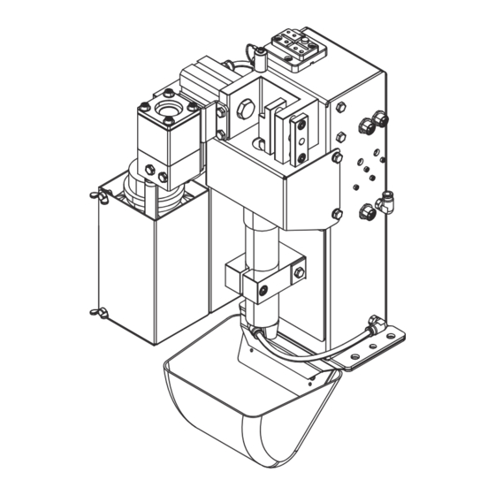
General Device concept The cleaning device is intended to automatically clean MIG/MAG welding torches. The cleaning device can be used to reliably clean the inside of gas nozzles and the face of the gas nozzles in a range of welding torch geometries. This significantly increases the service life of wearing parts. - Page 14 Robacta Reamer V Comfort Art.No. 42,0411,0333 Chargen No. 0.1A 6bar (87PSI) Warning notices on the cleaning device PLEASE NOTE! Risk of serious injury from mechanically moving parts. Keep the device de-energized and depressurized during main- tenance and servicing. Do not use the functions described here until you have fully...
- Page 15 Wear eye protection Warning before the device switches on automatically...
-
Page 16: Transport
Transport Transport equip- Transport the device using the following transport equipment: ment On a pallet using a counterbalanced lift truck On a pallet using a lift truck Manually WARNING! Danger from devices and objects falling. This can result in severe personal injury and damage to property. ▶... -
Page 17: Scope Of Supply And Options
Scope of Supply and Options Scope of supply Robacta Reamer V Comfort cleaning device Compressed air relief valve Leather seal for the parting agent injection device Wrench for cleaning motor Collecting container together with suitable holder Included in scope of supply, but not shown:... -
Page 19: Operating Controls, Connections And Mechanical Components
Operating controls, connections and mechanical components... -
Page 21: Safety
Safety Safety Please follow the safety rules below when using all the functions described in the "Operating controls, connections, and mechanical components" chapter. WARNING! Danger from incorrect operation and work that is not carried out properly. This can result in severe personal injury and damage to property. ▶... -
Page 22: Operating Controls, Connections And Mechanical Components
Operating controls, connections and mechanical components Operating con- trols, connec- tions, and mech- anical compon- ents Gas nozzle clamping device Holds the gas nozzle in place during the cleaning process Parting agent injection device includes the parting-agent injection nozzle; ensures that the parting agent only reaches the inside/face of the gas nozzle Parting-agent injection nozzle Sprays the parting agent into the gas nozzle and onto the face of the gas... - Page 23 (10) (11) (12) (13) Connection for actuator For switching an option Connection for sensor For connecting a sensor "Start cleaning" screw For manual testing The function of the gas nozzle clamping device (piston of the clamp- ing device extends) The immersion depth of the cleaning cutter in the gas nozzle (lifting device moves the cleaning motor upwards) The function of the cleaning motor (cleaning motor starts) (10)
- Page 24 (14) (15) (16) (17) (14) Touch sense See enclosed documentation 42,0410,2571 (15) Connection for sensor For connecting a sensor (16) Compressed air connection For supplying dry compressed air at 6 bar (86.99 psi) - for more informa- tion on compressed air quality, see section Specifications for the Com- pressed Air Supply on page...
- Page 25 (18) (19) (20) (21) (22) (18) TCP (ToolCenterPoint) with protective cover (19) Parting agent collecting container For collecting excess parting agent after the injection process (20) Parting agent container (21) Side cover (22) Fill-level control sensor...
-
Page 26: Harting Han12P (X1) Connecting Plug Configuration For The Robot Control
Harting Han12P (X1) connecting plug configura- tion for the robot control General CAUTION! Danger from overcurrent. Damage to the Harting Han12P (X1) connection power supply may result. ▶ Provide the power supply with 500 mA fuse protection against overcurrent. CAUTION! Danger due to long control line. -
Page 27: Installation And Startup
Installation and Startup... -
Page 29: Safety
Safety Safety Please follow the safety rules below when carrying out all the tasks described in the "Installation and commissioning" chapter. WARNING! Danger from incorrect operation and work that is not carried out properly. This can result in severe personal injury and damage to property. ▶... -
Page 30: Ensuring That The Cleaning Device Is Depressurized
Ensuring that To ensure that the cleaning device is depressurized, try to briefly activate the the cleaning cleaning device without the compressed air supply. To do this, proceed as follows: device is depres- Take protective measures: surized The cleaning cutter, lifting device, gas nozzle clamping device, wire cut- ter, and parting-agent injection nozzle could be activated. -
Page 31: Before Installation
Before installation Intended Use The cleaning device is used exclusively to mechanically clean Fronius robot weld- ing torches in automatic mode within the limits of technical data, especially to clean the gas nozzle and gas nozzle internal space. Any other use does not con- stitute proper use. -
Page 32: Measures To Ensure Safe Operation Of The Device When Operating Personnel Are Untrained
Measures to en- If untrained operating personnel have access to the device, the compressed air sure safe opera- supply to the device must be disconnected for the duration of this access in ac- tion of the cordance with "Performance Level d" of ISO 13849-1. device when op- erating person- We recommend FESTO's MS6-SV soft-start and quick exhaust valve for inter-... -
Page 33: Screwing The Cleaning Device To The Solid Surface
Screwing the Cleaning Device to the Solid Sur- face Screwing the WARNING! cleaning device and work stand Danger from devices falling or toppling over. to the surface This can result in severe personal injury and damage to property. ▶ Always screw the work stand to the surface. ▶... -
Page 34: Screw The Cleaning Device To The Surface
Attach the collecting container as shown Screw the clean- WARNING! ing device to the surface Danger from devices falling or toppling over. This can result in severe personal injury and damage to property. ▶ Always screw the cleaning device to the surface. ▶... - Page 35 Attach the collecting container as shown...
-
Page 36: Welding Torch Cleaning Position
Welding Torch Cleaning Position Welding torch The welding torch (gas nozzle) must be centered over the cleaning motor / clean- cleaning position ing cutter, with 1-2 mm (0.039 - 0.079 inches) distance to the protective cover. -
Page 37: Adjusting The Gas Nozzle Clamping Device
Adjusting the Gas Nozzle Clamping Device Adjusting the CAUTION! gas nozzle clamping device Danger due to incorrectly adjusted gas nozzle clamping device. The welding torch may be damaged. ▶ Set the gas nozzle clamping device so that no reaction forces can be trans- mitted to the robot. -
Page 38: Fitting The Cleaning Cutter
The cleaning cutter is not included in the scope of supply. Find the right cleaning cutter in the Spare Parts List for the welding torch used: https://spare- parts.fronius.com/ Remove the protective cover from the cleaning device Mount the protective cover on the cleaning device so that it is in its original... -
Page 39: Adjusting The Position Of The Cleaning Motor
Adjusting the Position of the Cleaning Motor Adjusting the position of the cleaning motor Remove protective cover (1) Remove the gas nozzle from the torch body Loosen the screw (2) on the lifting device Make sure that the lifting device (3) is in the bottom lift position Move the welding torch into the cleaning position (approx. -
Page 40: Configuring The Injection Device
The available leather seals can be found in the Spare Parts List: https://spare- parts.fronius.com/ Replace leather seal: Remove existing leather seal Fit leather seal with smaller diameter... -
Page 41: Install Electrically Controlled Wire Cutter (Option)
Install electrically controlled wire cutter (option) Functionality of The opening and closing of the electrically controlled wire cutter is triggered by the electrically an active signal from the robot control. controlled wire cutter Maximum wire The wire cutter can be used to cut wire electrodes with a diameter of up to diameter 1.6 mm (0.063 in.) Installing the... - Page 42 Use the mounting material supplied with the wire cutter. Ensure that the recesses in the spacers face the cleaning device. The wire cutter is electrically con- trolled via the robot control.
-
Page 43: Setting Up The Compressed Air Supply
Setting up the Compressed Air Supply Setting up the Set up the compressed air supply: cleaning device Disconnect the compressed air supply to the cleaning device and ensure that compressed air this compressed air supply remains disconnected while the tasks described supply, com- below are being carried out on the device pressed air relief... -
Page 44: Starting Up The Parting Agent Atomizer
Starting Up the Parting Agent Atomizer Filling the part- Only use the "Robacta Reamer" parting agent (item number 42,0411,8042) ing agent con- provided by the manufacturer. Its composition is specifically tailored for use with tainer (1 liter) the cleaning device. Correct operation is not ensured when other products are and connecting used. -
Page 45: Connecting The Parting Agent Container (10 Liter) To The Cleaning Device
Connecting the Only use the "Robacta Reamer" parting agent (item number 42,0411,8042) parting agent provided by the manufacturer. Its composition is specifically tailored for use with container (10 the cleaning device. Correct operation is not ensured when other products are liter) to the used. - Page 46 The existing 1-liter parting agent container and hose are no longer required if a 10-liter parting agent container is used. * "Long parting agent hose" option (42,0300,3007) The hose of the "long parting agent hose" option (42,0300,3007) must not be ex- tended.
- Page 47 To ensure proper operation of the injection device, do not position the parting agent container above the cleaning device: Do not position the parting agent container above the cleaning device. To ensure proper operation of the injection device, position the parting agent container no more than 1000 mm (39.37 inches) below the cleaning device: max.
-
Page 48: Manually Checking The Cleaning Device Functions
Manually Checking the Cleaning Device Functions Safety WARNING! For the following tasks, the cleaning device must be supplied with compressed air. This results in danger from the rotating cleaning cutter, cleaning motor mov- ing up/down, gas nozzle clamping device moving out/in, flying parts (chips, etc.), compressed air/parting agent mixture escaping from the parting-agent in- jection nozzle. - Page 49 Start cleaning Deactivate the function Spray in parting agent function Check the following while the function is executed: Whether the gas nozzle is adequately wetted with parting agent...
- Page 50 Inject parting agent Deactivate the function...
-
Page 51: Start Up The Cleaning Device
Start up the Cleaning Device Requirements The following requirements must be met in order to start up the cleaning device: for starting up If present, cleaning device work stand screwed tightly to the surface Cleaning device screwed tightly to the surface Gas nozzle clamping device adjusted Cleaning cutter fitted Position of the cleaning motor set... -
Page 52: Cleaning Program Sequence
Cleaning Program Sequence Safety CAUTION! Danger due to improper installation and commissioning. This can result in damage to property. ▶ The cleaning device's functions must be manually checked before starting automatic operation. ▶ Only start automatic mode once the cleaning device has been installed and commissioned properly. -
Page 53: Cleaning Program Sequence
Cleaning pro- Wire cutter option Start gram sequence Move to position C - Approx. 25 mm (0.98 in.) adjacent to wire cutter - Speed: High-speed mode Move to position D - Move into wire cutter - Speed: 10 cm/s (236.22 ipm) - External signal “Cut wire electrode”... - Page 54 Move to position A - Approx. 50 mm (1.97 in.) centrally above cleaning device - Speed: High-speed mode Output query (output signal Gas nozzle free) Query = low - Low or high (Gas nozzle clamped) Query = high Stop (Gas nozzle free) Move to position B (cleaning position) - Move into gas nozzle clamping device...
- Page 55 Reset - Input “Start cleaning” Wait 1.5 seconds Reset - Blow out compressed air through welding torch Query = low (Gas nozzle clamped) Output query (output signal Gas nozzle free) - Low or high Stop Query output = high (Gas nozzle free) Move to position A - Approx.
- Page 56 Move to position F (injection position) - Approx. 10-35 mm (0.39-1.38 in.) deep into the injection device - Speed: 10 cm/s (236.22 ipm) -Input "Spray in parting agent“ Wait 0.7 seconds Reset -Input "Spray in parting agent“ Move to position E - Approx.
-
Page 57: Cleaning Signal Sequence
Cleaning signal sequence Defined signal Start cleaning signal: input = Pin 1 on the Harting Han12P connecting plug (X1) Spray in parting agent signal: = Pin 2 on the Harting Han12P connecting plug (X1) Signal outputs Gas nozzle free: defined in time = Pin 5 on the Harting Han12P connecting plug (X1) Cleaning motor top: = Pin 6 at the Harting Han12P connecting plug (X1) - Page 58 Wire end reached: = Pin 8 on the Harting Han12P connecting plug (X1) Sensor option: = Pin 9 on Harting Han12P connecting plug (X1)
-
Page 59: Service, Maintenance And Disposal
Service, maintenance and disposal... -
Page 61: Safety
Safety Safety Follow the safety rules below when carrying out all the tasks described in the "Service, maintenance, and disposal" chapter. WARNING! Danger from incorrect operation and work that is not carried out properly. This can result in severe personal injury and damage to property. ▶... -
Page 62: Ensuring That The Cleaning Device Is Depressurized
CAUTION! Danger due to hot cleaning cutter as a result of operation. Serious burns may result. ▶ Before handling the cleaning cutter, allow it to cool to room temperature (+25 °C, +77 °F). Ensuring that To ensure that the cleaning device is depressurized, try to briefly activate the the cleaning cleaning device without the compressed air supply. -
Page 63: Service, Maintenance And Disposal
Service, maintenance and disposal General The cleaning device does not usually require maintenance. To ensure the cleaning device remains operational over time, there are a number of care and mainten- ance tasks that need to be carried out, however: Before every Check the fill level in the parting agent container and top up the parting start-up agent container if necessary... -
Page 64: Empty Parting Agent Collecting Container
Lightly oil the guides on the lifting device's lifting cylinder Restore the original state of the device Empty parting agent collecting container Unlock housing (slide up ~ 3 cm / 1.18 inches) Rotate housing Pull the housing off the parting agent hose Dispose of old parting agent properly Return the empty parting agent collecting container together with the hous- ing to its original position... -
Page 65: Disposal
Disposal Materials should be disposed of according to valid local and national regulations. -
Page 67: Troubleshooting
Troubleshooting... -
Page 69: Safety
Safety Safety Follow the safety rules below when carrying out all the tasks described in the "Troubleshooting" chapter. WARNING! Danger from incorrect operation and work that is not carried out properly. This can result in severe personal injury and damage to property. ▶... -
Page 70: Ensuring That The Cleaning Device Is Depressurized
CAUTION! Danger due to hot cleaning cutter as a result of operation. Serious burns may result. ▶ Before handling the cleaning cutter, allow it to cool to room temperature (+25 °C, +77 °F). Ensuring that To ensure that the cleaning device is depressurized, try to briefly activate the the cleaning cleaning device without the compressed air supply. -
Page 71: Troubleshooting
Troubleshooting Errors in the Parting agent is not injected Program Se- Parting agent container is full quence Cause: Injection quantity too low Remedy: Extend injection time Cause: Intake filter of the parting agent hose in the parting agent container is contaminated Remedy: Clean the suction filter of the parting agent hose with compressed air Starting Up the Parting Agent At-... - Page 72 Lifting device does not move up or down Cause: Compressed air supply missing Remedy: Set up the compressed air supply Cause: No signal from robot Remedy: Check robot program Cause: Solenoid valve has mechanical fault Remedy: Contact service team (solenoid valve needs replacing) Cause: Throttle valve cannot be adjusted or is faulty Remedy:...
-
Page 73: Technical Data
Technical data... -
Page 75: Technical Data
Technical data Robacta Reamer Supply voltage + 24 V DC V Comfort Nominal output 2.4 W Nominal pressure 6 bar 86.99 psi Air consumption 420 l/min 443.81 qt./min Thread identification compressed air con- G ¼“ nection Standard I/O (X1) Input: + 24 V DC/max. 100 mA Output: + 24 V DC/max. -
Page 77: Appendix
Appendix... -
Page 79: Declaration Of Conformity
Declaration of conformity...
Need help?
Do you have a question about the Robacta Reamer V Comfort and is the answer not in the manual?
Questions and answers