Fronius Robacta Operating Instructions Manual
Mig/mag robot welding torch
Hide thumbs
Also See for Robacta:
- Operating instructions manual (88 pages) ,
- Operating instructions manual (76 pages)

Related Manuals for Fronius Robacta


Summary of Contents for Fronius Robacta
- Page 1 / Perfect Charging / Perfect Welding / Solar Energy Operating Instructions Robacta Robacta Twin MIG/MAG robot welding torch MTB /i MTB /d MIG/MAG 42,0410,1933 003-07112019...
-
Page 3: Dear Reader
Dear reader, Thank you for the trust you have placed in our company and congra- tulations on buying this high-quality Fronius product. These instructions will help you familiarise yourself with the product. Reading the instructions carefully will enable you to learn about the many different features it has to offer. - Page 4 For hose pack lengths up to 6 metres (19 ft. 8.22 in.), the Robac- ta and Robacta Twin robot hose packs represent a low-cost alterna- tive to the motorised Robacta Drive or Robacta Drive Twin robot hose...
- Page 5 Safety WARNING! Work perfor- med incorrectly can cause serious injury and dama- ge. The activities described must only be carried out by trained and qualified personnel. Pay particular attention to the enclosed „Safety rules“ docu- WARNING! An electric shock can be fatal. Only carry out the activities described the power source mains switch is in the „O“...
- Page 6 Safety WARNING! An electric shock can be fatal. There is also a risk of injury from filler wire emerging. Switch the power source mains switch to the „O“ position before cleaning the welding torch and checking its components. CAUTION! When a welding torch becomes extremely hot from use, it represents a fire risk.
- Page 7 Safety CAUTION! Danger of scalding by hot coolant. Never check the water connec- tions until they have cooled down. CAUTION! Risk of injury from unsatisfactory connections. All cables, leads and hose packs must be proper- ly secured, undamaged, insula- ted and adequately dimensio- ned.
- Page 8 (m/min) t (s) 2,5 3...
-
Page 9: Controls And Connections
Controls and connec- tions „Feeder inching“ button for feeding in the filler wire with no accompanying flow of gas or current. As long as the feeder inching button is held down, the filler wire is fed in. The feeder inching speed depends on the length of time that the feeder inching button is held down (Fig. - Page 11 The Robacta clamp and Robacta adjusting clip are for fitting the Robacta hose pack to the robot or to the welding machine. The adjusting clip supports TCP correction on the robot. The Robac-...
- Page 12 Drill / Ø5,8 Reamer / Ø6G7...
- Page 13 Fitting the mounting bracket (standard) WARNING! Work perfor- med incorrectly can cause serious injury to people and damage to property. This instal- lation must only be carried out by trained and qualified person- nel. Observe the safety rules in the power source operating instructions.
- Page 14 Drill / Ø5,8 Reamer / Ø6G7...
- Page 15 Fitting the mounting bracket (individually) WARNING! Work perfor- med incorrectly can cause serious injury to people and damage to property. This instal- lation must only be carried out by trained and qualified person- nel. Observe the safety rules in the power source operating instructions.
- Page 17 Robacta torch necks - dismantling and as- sembling NOTE! Risk of coolant escaping through loose union nut. When fitting the torch neck, ensure that the union nut is securely fastened: Tighten union nut using a flat spanner. For a defined, reproducible tighte-...
- Page 19 Dismantling and as- sembling Robacta Twin torch necks NOTE! Risk of coolant escaping through loose union nuts. When fitting the Twin torch neck, ensure that the union nuts are securely fastened: Tighten union nuts using flat spanner and torque wrench, tightening torque = 18 ±2 Nm.
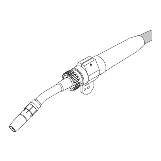
- Page 21 Connecting the robot hose pack Connection for torch blow-off option NOTE! Shielding gas mixed with extraneous air has an adverse effect on welding results. The end of the hose must be sealed off with the stopper supplied if the torch blow-off connection is not in use Do not connect the hose if no compressed air is connected...
- Page 23 Correct laying of the robot hose pack To attain optimum wirefeed, obser- ve the following when laying the hose pack: Do not kink the hose pack Arrange the hose pack in as straight a line as possible Do not overstretch the hose pack, especially in robot mode Keep bends in the hose pack as wide as possible...
- Page 25 Replacing the gas nozz- le obacta 160/300/500 Robacta 700/700 Time NOTE! The O-rings may be damaged if the gas nozzle is removed or replaced incorrectly. Always open the union nut before removing or replacing the gas nozzle. Important! When replacing the...
- Page 27 Replacing welding torch wearing parts - Robacta Robacta 160 Robacta 280 Robacta 300 / 500 Robacta 400 Robacta 700 / 700 TIME Robacta 2500...
- Page 29 Replacing welding torch wearing parts - Robacta Robacta 5000...
- Page 31 Replacing welding torch wearing parts - Robacta Twin Important! Always use two identi- cal contact tubes. NOTE! Risk of serious damage. ALWAYS observe the work se- quence and the specified torques. Instead of the standard tool provided, a torque wrench and appropriate box spanner are also available.
- Page 32 1,3* 1,6* 1,6* 1,9* 2,3 2,9* inch .023 .030 .035 .040 .045 1/16 .043 .051* .063* .063* .075* .091 .063 .075 .075 .091 .115*...
- Page 33 Standard values for steel liners Important! Inner liners are sup- plied in overlengths. Use bare steel liner * recommended...
- Page 34 i n . . 3 5 ( . 3 n . ) - . 0...
- Page 35 Fitting the steel liner Robacta 280 / 400 Ro- bacta 2500 / 5000 Robacta Twin Torch neck with nozzle fitting screwed on NOTE! When cutting the liner to length, make sure that no flash protrudes into the liner Place the cutting pliers at a...
- Page 36 n . ) ( . 3 i n . n . ) ( . 6 i n . ( - . i n . ( - .
- Page 37 Fitting the steel liner Robacta 160/300/500 Robacta 700/700 Time Torch neck with no nozzle fitting screwed on NOTE! When cutting the liner to length, make sure that no flash protrudes into the liner Place the cutting pliers at a slight angle (flash is pulled...
- Page 38 inch inch .023 .030 .035 .040 .045 1/16 .023 .030 .035 .040 .045 1/16 .043 .043 .059 .059 .079 .098 .059 .059 .059 .059 .079 .098...
- Page 39 Standard values for graphite combination liners and Teflon li- ners NOTE! For aluminium applications, choose the next largest contact tube diameter. Important! Inner liners are sup- plied in overlengths. Figure 1: Graphite combination liners Figure 2: Teflon liners...
- Page 40 i n . . 0 8 ( . 0...
- Page 41 Fitting plastic liners (Fronius connection with no wirefeeding nozzle) applies to: Teflon liners Combination liners Graphite liners NOTE! Feed the inner liner as close to the feed rollers as possible, but do not let them touch. NOTE! Before feeding in the filler wire, round off the end of the wire.
- Page 43 Fitting plastic liners (Fronius connection with wirefeeding nozz- applies to: Teflon liners Combination liners Graphite liners Plastic component - do not overtighten! NOTE! Guide the wirefee- ding nozzle as close to the feed rollers as possible, but do not let them touch.
- Page 44 (.04 - .08 in.) 1-2 mm...
- Page 45 Fitting plastic liner (Euro connection) applies to: Teflon liners Combination liners Graphite liners Inlet nozzle option (42,0001,5621) NOTE! Feed the inner liner or inlet nozzle as close to the feed rollers as possible, but do not let them touch. NOTE! Before feeding in the filler wire, round off the end of the wire.
-
Page 47: Care, Maintenance And Disposal
Care, maintenance and disposal Regular preventive maintenance of the welding torch is essential for problem-free operation. The welding torch is subjected to high tempera- tures and heavy soiling. The welding torch therefore requires more frequent maintenance than other components in the welding system. - Page 48 Robacta 700...
- Page 49 Replace worn out contact tube Remove welding spatter from gas nozzle (e.g. manually, by blowing off, or by using a Robacta Reamer or Robacta TC 1000) If there is dirt that cannot be removed from around the nozzle join, replace the gas...
- Page 51 Care, maintenance and disposal Every time the wirespool is chan- ged: Recommended: replace inner liner Clean wirefeeding hose with reduced compressed air Clean wearing parts before fitting Disposal: Dispose of in accordance with the applicable national and local regulations.
-
Page 53: Recognising Faulty Wearing Parts
Recognising faulty wearing parts Insulating parts Notches Burned off or torn middle Scorched or torn-off shoul- ders Nozzle fittings Notches and burns on the front edge heavily covered in welding spatter Spatter guard Burned-off outside edges Notches Contact tubes Worn out (oval) wire entry and wire exit holes Heavily covered in welding spatter... -
Page 54: Troubleshooting
Troubleshooting No welding current Mains switch is on, indicators on the power source are lit, shielding gas available Cause: Incorrect earth (ground) connection Remedy: Check the earth (ground) connection and clamp for correct polarity Cause: There is a break in the current cable in the welding torch Remedy: Replace the torch No shielding gas... - Page 55 Cause: Welding spatter in the gas nozzle Remedy: Remove welding spatter Poor welding properties Cause: Turbulence caused by too high a rate of shielding gas flow Remedy: Reduce amount of shielding gas, recommended shielding gas quantity (l/min) = wire diameter (mm) x 10 (e.g.
- Page 56 The welding torch becomes very hot Cause: Loose union nut on central connector Remedy: Tighten the union nut Cause: The welding torch has been operated beyond its maximum number of amps. Remedy: Reduce welding power or use a higher capacity torch Cause: The design dimensions of the torch are not sufficient for this task Remedy:...
- Page 57 Weld seam porosity Cause: Spattering in the gas nozzle, causing inadequate gas-shielding of the weld seam Remedy: Remove welding spatter Cause: Either the shielding gas hose has holes in it, or the hose is not connected properly Remedy: Replace shielding gas hose Cause: The O-ring seals on the connection points have been cut through or are faulty Remedy:...
- Page 62 Technical Data Torch necks Explanation of symbols: Water-cooled torch neck X ..Duty cycle in % ED* ..Duty cycle ..max. welding current in A (M6) ..with contact tube M6 (M8) ..with contact tube M8 Electrode diameter Ø...
- Page 63 1,0-1,6 1,0-1,6 0,8-1,2 Ø [in.] .031-.063 .039-.063 .039-.063 .031-.047 Robacta 5000 Robacta 7000 MTW 500-M (Con-Drive) Laser HD/W X / I (10 min / 40°C) [%] / [A] M21 (EN 439) [%] / [A] [%] / [A] 100 / 500...
- Page 64 MTB 500i W/R MTB 330i W/R X / I (10 min / 40°C) [%] / [A] M21 (EN 439) [%] / [A] [%] / [A] 100 / ED* 500 100 / ED* 330 X / I (10 min / 40°C) [%] / [A] C1 (EN 439) [%] / [A]...
- Page 65 Technical Data Hosepacks Explanation of symbols: Water cooling Length of the hosepack X .... Duty cycle in % ..max. welding current in A Electrode diameter Ø Ø Lowest cooling power as per IEC 60974-2, depends on the length of the hosepack Voltage measurement (V-Peak): for mechanically driven welding torches: 141 V...
- Page 66 Robacta Robacta W/CB-PAP X / I (10 min / 40°C) [%] / [A] M21 (EN 439) [%] / [A] [%] / [A] 100 / 700 100 / 500 X / I (10 min / 40°C) [%] / [A] C1 (EN 439)
- Page 68 FRONIUS INTERNATIONAL GMBH Froniusstraße 1, A-4643 Pettenbach, Austria E-Mail: sales@fronius.com www.fronius.com Under www.fronius.com/contact you will find the addresses of all Fronius Sales & Service Partners and locations Find your spareparts online...
Need help?
Do you have a question about the Robacta and is the answer not in the manual?
Questions and answers