Table of Contents
Troubleshooting

Related Manuals for Fronius WF 15i


Summary of Contents for Fronius WF 15i
- Page 1 / Perfect Charging / Perfect Welding / Solar Energy Operating instructions WF 15i WF 15i n.S. WF 25i WF 30i 42,0426,0116,EN 035-18112021 Fronius prints on elemental chlorine free paper (ECF) sourced from certified sustainable forests (FSC).
-
Page 3: Table Of Contents
Contents Safety rules Explanation of safety notices General Proper use Environmental conditions Obligations of the operator Obligations of personnel Mains connection Protecting yourself and others Danger from toxic gases and vapours Danger from flying sparks Risks from mains current and welding current Meandering welding currents EMC Device Classifications EMC measures... - Page 4 Safety Troubleshooting Care, maintenance and disposal General Safety Every start-up Every 6 months Disposal Technical data Technical data WF 15i WF 15i n.S. WF 25i WF 30i HP 70i HP 95i HP 120i HP 70i, HP PC Cable HD 70...
-
Page 5: Safety Rules
Safety rules Explanation of DANGER! safety notices Indicates immediate danger. ▶ If not avoided, death or serious injury will result. WARNING! Indicates a potentially hazardous situation. ▶ If not avoided, death or serious injury may result. CAUTION! Indicates a situation where damage or injury could occur. ▶... -
Page 6: Environmental Conditions
The device is intended solely for the welding processes specified on the rating plate. Any use above and beyond this purpose is deemed improper. The manufacturer shall not be held liable for any damage arising from such usage. Proper use includes: carefully reading and following all the instructions given in the operating instructions studying and obeying all safety and danger notices carefully performing all stipulated inspection and maintenance work. -
Page 7: Protecting Yourself And Others
This may affect a number device types in terms of: Connection restrictions Criteria with regard to the maximum permissible mains impedance Criteria with regard to the minimum short-circuit power requirement at the interface with the public grid see "Technical data" In this case, the plant operator or the person using the device should check whether the device may be connected, where appropriate by discussing the matter with the power supply company. -
Page 8: Danger From Flying Sparks
Fumes and hazardous gases must not be breathed in must be extracted from the working area using appropriate methods. Ensure an adequate supply of fresh air. Ensure that there is a ventilation rate of at least 20 m³ per hour at all times. Otherwise, a welding helmet with an air supply must be worn. -
Page 9: Meandering Welding Currents
Make sure that you and others are protected with an adequately insulated, dry base or cover for the earth or ground potential. This base or cover must extend over the entire area between the body and the earth or ground potential. All cables and leads must be secured, undamaged, insulated and adequately dimen- sioned. -
Page 10: Emc Device Classifications
Position the device with sufficient insulation against electrically conductive environments, such as insulation against conductive floor or insulation to conductive racks. If power distribution boards, twin-head mounts, etc., are being used, note the following: The electrode of the welding torch / electrode holder that is not used is also live. Make sure that the welding torch / electrode holder that is not used is kept sufficiently insu- lated. -
Page 11: Emf Measures
EMF measures Electromagnetic fields may pose as yet unknown risks to health: Effects on the health of persons in the vicinity, e.g. those with pacemakers and hear- ing aids Individuals with pacemakers must seek advice from their doctor before approaching the device or any welding that is in progress For safety reasons, maintain as large a distance as possible between the welding power-leads and the head/torso of the welder... -
Page 12: Requirement For The Shielding Gas
If the wirefeeder is attached to a crane holder during welding, always use a suitable, in- sulated wirefeeder hoisting attachment (MIG/MAG and TIG devices). If the device has a carrying strap or handle, this is intended solely for carrying by hand. The carrying strap is not to be used if transporting with a crane, counterbalanced lift truck or other mechanical hoist. -
Page 13: Danger From Escaping Shielding Gas
Danger from es- Risk of suffocation from the uncontrolled escape of shielding gas caping shielding Shielding gas is colourless and odourless and, in the event of a leak, can displace the oxygen in the ambient air. Ensure an adequate supply of fresh air with a ventilation rate of at least 20 m³/hour. Observe safety and maintenance instructions on the shielding gas cylinder or the main gas supply. -
Page 14: Commissioning, Maintenance And Repair
Always fasten the shielding gas cylinder securely and remove it beforehand if the device is to be transported by crane. Only the manufacturer's original coolant is suitable for use with our devices due to its properties (electrical conductibility, anti-freeze agent, material compatibility, flammability, etc.). -
Page 15: Disposal
(e.g. relevant product standards of the EN 60 974 series). Fronius International GmbH hereby declares that the device is compliant with Directive 2014/53/EU. The full text on the EU Declaration of Conformity can be found at the follow- ing address: http://www.fronius.com... -
Page 17: General
General... -
Page 19: General
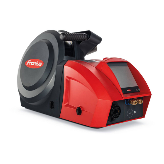
General Device concept The wire-feed units WF 15i, WF 25i, WF 30i are fitted with a cover for wirespools with an outer diameter of up to 300 mm (11.81 in). Also available is the WF 15i n.S. (no Spool) variant without an integrated wirespool holder. - Page 20 Attention: Les pièces peuvent être à la tension de soudage 40,0006,3035 WF 15i n.S. Do not use the functions described here until you have thoroughly read and understood the following documents: these operating instructions all the operating instructions for the system components, especially the safety rules Welding is dangerous.
-
Page 21: Controls, Connections And Mechanical Components
Controls, connections and mechan- ical components... -
Page 23: Controls, Connections And Mechanical Components
Function Coolant return connection (red) - is fitted as standard on WF 15i, WF 15i n.S., WF 30i, as an option for WF 25i for connecting the coolant hose from the welding torch hosepack... -
Page 24: Rear Of Wire-Feed Unit
SpeedNet cable Shielding gas connection Function Coolant return connection (red) - is fitted as standard on WF 15i, WF 15i n.S., WF 30i, as an option for WF 25i for connecting the coolant hose from the interconnecting hosepack Coolant flow connection (blue) - is fitted as standard on WF 15i, WF 15i n.S., WF 30i, as an option for WF 25i... -
Page 25: Wire-Feed Unit Underside
Function Wirespool holder (not in the case of WF 15i n.S.) for holding standard wirespools with a max. outer diameter of 300 mm (11.81 in) and max. weight of 19 kg (41.89 lbs.) 4-roller drive Protective cover for the 4-roller drive... -
Page 26: Optional Control Panels
Optional control panels Safety WARNING! Danger from incorrect operation and work that is not carried out properly. This can result in serious personal injury and damage to property. ▶ All the work and functions described in this document must only be carried out by technically trained and qualified personnel. -
Page 27: Opt/I Wf Gas Test & Wire Threading
Adjuster functions during electrode welding Influencing the arc-force dynamic: 0 = soft, low-spatter arc 10 = harder, more stable arc Adjuster functions during TIG welding Setting the welding current Not active OPT/i WF gas test Function & wire threading OPT/i WF gas test & wire thread- Operating status LED lights up green when the device is ready for use... - Page 28 NOTE! Risk when retracting the wire electrode. No winding onto the wirespool. ▶ Do not allow long lengths of wire electrode to be retracted, as the wire electrode is not wound onto the wirespool when retracted. If there was a ground earth connection with the contact tip before the wire retract button was pressed, the wire electrode will be retracted when the button is pressed until it is short-circuit-free - it retracts by no more than 10 mm (0.39 in.) with each press of the button.
-
Page 29: Opt/I Wf Standard Control Panel
OPT/i WF Stand- ard control panel (10) (14) (11) (13) (12) - Page 30 Function Parameter selection button (left) for selecting the parameters listed below. The corresponding indicator lights up when a parameter is selec- ted. Material thickness *) in mm or inches Current *) current in A Before the start of welding, the machine automatically displays a standard value based on the programmed parameters.
- Page 31 Function Parameter selection button (right) for selecting the parameters listed below. The corresponding indicator lights up when a parameter is selec- ted. Arc length correction for correcting the arc length - ... shorter arc length 0 ... neutral arc length + ...
- Page 32 Function Adjusting dial with turn/press function for changing the arc length correction, voltage, pulse/ dynamic correction parameters for selecting the job number EasyJob button for saving, opening and deleting EasyJobs. The LED in the button indicates that EasyJob is selected How it works: Press and hold the button for 3 seconds = save EasyJob (all current settings are saved).
- Page 33 Function Hold indicator the actual values are displayed automatically at the end of each welding operation (current, voltage, wire feed speed, etc.). The actual values are displayed through the HOLD indicator lighting up. Intermediate arc indicator a spatter-prone intermediate arc occurs between the short arc and the spray arc.
-
Page 35: Installation And Commissioning
Installation and commissioning... -
Page 37: Before Installation And Commissioning
60° to the vertical The WF 15i, WF 25i and WF 30i wirefeeders can be set up and operated outdoors in accordance with degree of protection IP23. Avoid direct wetting (e.g. from rain). -
Page 38: Placing Wire-Feed Unit On Swivel Pin Holder
Placing wire-feed unit on swivel pin holder Safety WARNING! Danger from electrical current. This can result in serious personal injury and damage to property. ▶ Before starting work, switch off all devices and components involved and disconnect them from the grid. ▶... -
Page 39: Connecting Wire-Feed Unit To Power Source
Connecting wire-feed unit to power source Safety WARNING! Danger from electrical current. This can result in serious personal injury and damage to property. ▶ Before starting work, switch off all devices and components involved and disconnect them from the grid. ▶... -
Page 40: Connecting The Extension Hosepack
Connecting the WARNING! extension hosep- Danger from electric current due to defective system components and incorrect operation. This can result in serious personal injury and damage to property. ▶ All cables, leads and hosepacks must always be securely connected, undamaged and correctly insulated. -
Page 42: Connecting The Welding Torch
Connecting the welding torch Safety WARNING! Danger from electrical current. This can result in serious personal injury and damage to property. ▶ Before starting work, switch off all devices and components involved and disconnect them from the grid. ▶ Secure all devices and components involved so they cannot be switched back on. ▶... -
Page 43: Inserting/Replacing Feed Rollers
Inserting/replacing feed rollers Safety WARNING! Danger from electrical current. This can result in serious personal injury and damage to property. ▶ Before starting work, switch off all devices and components involved and disconnect them from the grid. ▶ Secure all devices and components involved so they cannot be switched back on. ▶... - Page 44 CAUTION! Danger from exposed feed rollers. This can result in injuries. ▶ Always fit the protective cover of the 4-roller drive after inserting or replacing a feed roller.
-
Page 45: Inserting The Wirespool, Inserting The Basket-Type Spool
Inserting the wirespool, inserting the basket-type spool Safety WARNING! Danger from electrical current. This can result in serious personal injury and damage to property. ▶ Before starting work, switch off all devices and components involved and disconnect them from the grid. ▶... -
Page 46: Installing The Basket-Type Spool
Installing the bas- WARNING! ket-type spool Danger from falling basket-type spool due to missing basket-type spool adapter. This can result in severe personal injury and damage to property. ▶ When working with basket-type spools, only use the basket-type spool adapter in- cluded in the scope of supply. - Page 47 WARNING! Gefahr durch herabfallende Korbspule bei seitenverkehrt aufgesetztem Sicherung- sring. Schwerwiegende Personen- und Sachschäden können die Folge sein. ▶ Den Sicherungsring immer wie nachfolgend dargestellt aufsetzen.
-
Page 48: Threading The Wire Electrode
Threading the wire electrode General NOTE! If there is no wire threading button on the wire-feed unit, use the wire threading button of another of the manufacturer's system components to thread the wire, for example the power source wire threading button. The wire threading button functions in the same way for all system components from the manufacturer. -
Page 49: Threading The Wire Electrode
Threading the CAUTION! wire electrode Danger from welding current and accidental ignition of an arc. This can result in severe personal injury and damage to property. ▶ Before starting work, disconnect the ground earth connection between the welding system and the workpiece. CAUTION! Danger from emerging wire electrode. - Page 50 Contact pressure preferred values for U-groove rollers: Steel: 4 - 5 CrNi: 4 - 5 Tubular cored electrodes: 2 - 3...
-
Page 51: Adjust The Brake
Adjust the brake General NOTE! Overrunning of the brake can result in damage to property. ▶ After releasing the torch trigger / wire threading button the wirespool must stop un- reeling. ▶ If it continues unreeling, readjust the brake. Adjusting the CAUTION! brake Danger from welding current and accidental ignition of an arc. -
Page 52: Design Of The Brake
STOP Design of the WARNING! brake Danger from incorrect installation. This can result in severe personal injury and damage to property. ▶ Do not dismantle the brake. ▶ Maintenance and servicing of brakes is to be carried out by trained, quali- fied personnel only. -
Page 53: Start-Up
(not for WF 15i n.S.) Wire electrode threaded in Feed roller contact pressure set Brake set (not for WF 15i n.S.) All covers closed, all side panels in place, all protection devices intact and in their proper place General The wire-feed unit is started by pressing the torch trigger (for manual applications) or by means of a welding start-up signal (for automatic applications). -
Page 55: Troubleshooting, Maintenance And Disposal
Troubleshooting, maintenance and disposal... -
Page 57: Troubleshooting
Troubleshooting Safety WARNING! Danger from incorrect operation and work that is not carried out properly. This can result in serious personal injury and damage to property. ▶ All the work and functions described in this document must only be carried out by technically trained and qualified personnel. - Page 58 Power source does not function Mains switch is on, but indicators are not lit up Cause: There is a break in the mains lead; the mains plug is not plugged in Remedy: Check the mains lead, ensure that the mains plug is plugged in Cause: Mains socket or mains plug faulty Remedy:...
- Page 59 Irregular wire feed speed Cause: Braking force has been set too high Remedy: Loosen the brake Cause: Hole in the contact tip is too narrow Remedy: Use a suitable contact tip Cause: Faulty inner liner in welding torch Remedy: Check the inner liner for kinks, dirt, etc. and replace if necessary Cause: The feed rollers are not suitable for the wire electrode being used Remedy:...
- Page 60 Poor weld properties Cause: Incorrect welding parameters Remedy: Check the settings Cause: Poor ground earth connection Remedy: Ensure good contact to workpiece Cause: Inadequate or no protective gas shield Remedy: Check the pressure regulator, gas hose, gas solenoid valve, torch gas con- nection, etc.
-
Page 61: Care, Maintenance And Disposal
Care, maintenance and disposal General Under normal operating conditions, the device requires only a minimum of care and maintenance. However, it is vital to observe some important points to ensure the welding system remains in a usable condition for many years. Safety WARNING! Danger from incorrect operation and work that is not carried out properly. -
Page 62: Disposal
Open covers, remove device side panels and clean inside of device with dry re- duced compressed air. After cleaning, restore device to its original state. Disposal Dispose of in accordance with the applicable national and local regulations. -
Page 63: Technical Data
Technical data... -
Page 65: Technical Data
25.91 x 11.10 x 14.25 in. Weight 13 kg 28.66 Ib. *) D.C. = duty cycle WF 15i n.S. Supply voltage 24 V DC / 60 V DC Nominal current 0,5 A / 1 A Welding current at 10 min / 40 °C (104 °F) - Page 66 D.C.* 500 A 450 A 360 A Maximum shielding gas pressure 7 bar 101.53 psi Coolant Original Fronius Maximum coolant pressure 5 bar 72.53 psi Wire feed speed 1 - 25 m/min 39.37 - 984.25 ipm Wire drive 4-roller drive...
- Page 67 650 A 600 A 500 A Maximum shielding gas pressure 7 bar 101.53 psi Coolant Original Fronius Maximum coolant pressure 5 bar 72.53 psi Wire feed speed 1 - 30 m/min 39.37 - 1181.10 ipm Wire drive 4-roller drive Wire diameter 0,8 - 1,6 mm .03 - .06 in.
- Page 68 HP 70i, HP PC Welding current at 10 min/40 °C (104 °F) 60% ED* / 600 A Cable HD 70 100% ED* / 500 A ED = Duty cycle...
- Page 72 SPAREPARTS ONLINE Fronius International GmbH Froniusstraße 1 4643 Pettenbach Austria contact@fronius.com www.fronius.com Under www.fronius.com/contact you will find the adresses of all Fronius Sales & Service Partners and locations.
Need help?
Do you have a question about the WF 15i and is the answer not in the manual?
Questions and answers