Table of Contents
Advertisement
/ Perfect Charging /
Perfect Welding
Robacta Reamer V Easy
Robacta Reamer V Easy Han6P J
Robacta Reamer V
42,0426,0094,EN 035-09102019
Fronius prints on elemental chlorine free paper (ECF) sourced from certified sustainable forests (FSC).
/ Solar Energy
Operating Instructions
Spare parts list
Welding torch cleaning
Advertisement
Table of Contents
Troubleshooting

Related Manuals for Fronius Robacta Reamer V Easy


Summary of Contents for Fronius Robacta Reamer V Easy
- Page 1 / Solar Energy Operating Instructions Robacta Reamer V Easy Spare parts list Robacta Reamer V Easy Han6P J Welding torch cleaning Robacta Reamer V 42,0426,0094,EN 035-09102019 Fronius prints on elemental chlorine free paper (ECF) sourced from certified sustainable forests (FSC).
- Page 3 Thank you for the trust you have placed in our company and congratulations on buying this high-quality Fronius product. These instructions will help you familiarise yourself with the product. Reading the instructions carefully will enable you to learn about the many different features it has to offer.
-
Page 5: Table Of Contents
Controls, connections and mechanical components Safety................................. Safety..............................Robacta Reamer V Easy, Robacta Reamer V Easy Han6P J control elements, connections and mechan- ical components ............................Robacta Reamer V Easy, Robacta Reamer V Easy Han6P J control elements, connections and me- chanical components .......................... - Page 6 V) ................................Checking the Robacta Reamer V Easy and Robacta Reamer V Easy Han6P J functions......General ..............................Manually checking the Robacta Reamer V Easy and Robacta Reamer V Easy Han6P J functions ..Manually checking Robacta Reamer V functions ..................
- Page 7 Cleaning program on the Robacta Reamer V Easy and Robacta Reamer V Easy Han6P J ....Cleaning program on the Robacta Reamer V..................Cleaning signal waveform on the Robacta Reamer V Easy and Robacta Reamer V Easy Han6P J ..Signal inputs ............................
-
Page 9: Safety Rules
Proper use The device is to be used exclusively for its intended purpose. The device is intended solely for the mechanical cleaning of Fronius robot welding torches in automatic mode. Any use above and beyond this purpose is deemed improper. The manufacturer shall not be held liable for any damage arising from such usage. -
Page 10: Obligations Of The Operator
Relative humidity: up to 50 % at 40 °C (104 °F) up to 90 % at 20 °C (68 °F) Keep ambient air free from dust, acids, corrosive gases and substances, etc. Can be used at altitudes of up to 2000 m (6500 ft) Obligations of the The operator must only allow persons to work with the device who: operator... -
Page 11: Protecting Yourself And Others
During operation Ensure that all covers are closed and fitted properly Keep all covers closed Protecting your- Anyone working with the device exposes themselves to numerous risks. In addition to self and others these Operating Instructions, the safety rules of the manufacturer of the entire welding sys- tem must also be observed. -
Page 12: Emf Measures
EMF measures Electromagnetic fields may pose as yet unknown risks to health: effects on the health of others in the vicinity, e.g. wearers of pacemakers and hearing aids wearers of pacemakers must seek advice from their doctor before approaching the de- vice or any welding that is in progress for safety reasons, keep distances between the welding cables and the welder's head/ torso as large as possible... -
Page 13: Commissioning, Maintenance And Repair
Commissioning, It is impossible to guarantee that bought-in parts are designed and manufactured to meet maintenance and the demands made of them, or that they satisfy safety requirements. repair Use only original spare and wearing parts (also applies to standard parts). Do not carry out any modifications, alterations, etc. -
Page 15: General
General... -
Page 17: General
The options available for each cleaning device are shown on the following pages. Device concept - The gas nozzle clamping device on the front of the Robacta Reamer V Easy Han6P J holds Robacta Reamer the gas nozzle in place during cleaning. A cleaning cutter is used to clean the nozzle. After... -
Page 18: Applications
The locations of the warning notices are shown on the Robacta Reamer V as an example. The warning notices are all in the same place on the Robacta Reamer V Easy, Robacta Reamer V Easy Han6P and Robacta Reamer V Easy Han6P J. - Page 19 Type Art.No. Chargen No. Wels - Austria 24 V p max 6 bar (87psi.) Warning notices on the cleaning device WARNING! Risk of serious injury from: mechanically powered components compressed air/parting agent mixture escaping from the parting-agent injection nozzle flying parts (shavings, etc.) Keep the device free from current and pressure during maintenance and servicing.
- Page 20 Wear eye protection Notice warning of automatic start-up of the device...
-
Page 21: Transport
Transport Vehicles The device is to be transported by the following vehicles: on pallets using a counterbalanced lift truck on pallets using a lift truck manually WARNING! Equipment that falls or topples over can cause serious or even fatal injury. ►... -
Page 22: Robacta Reamer V Easy Scope Of Supply And Options
Robacta Reamer V Easy scope of supply and op- tions Robacta Reamer V Easy scope of NOTE! supply The "Robacta Reamer" parting agent (item number 42,0411,8042) and the cle- aning cutter are not part of the scope of supply. Robacta Reamer V Easy cleaning... -
Page 23: Robacta Reamer V Easy Han6P J Scope Of Supply, Options And Required Components
Robacta Reamer V Easy Han6P J scope of supply, options and required components Robacta Reamer V Easy Han6P J NOTE! scope of supply The "Robacta Reamer" parting agent (item number 42,0411,8042) and the cle- aning cutter are not part of the scope of supply. - Page 24 Mounting plates for the wire cutter including fixings...
-
Page 25: Robacta Reamer V Scope Of Supply And Options
Robacta Reamer V scope of supply and options Robacta Reamer V scope of supply NOTE! The "Robacta Reamer" parting agent (item number 42,0411,8042) and the cle- aning cutter are not part of the scope of supply. Robacta Reamer V cleaning device Spatter tray retainer Spatter tray Tightening key for cleaning motor... -
Page 27: Controls, Connections And Mechanical Components
Controls, connections and mechani- cal components... -
Page 29: Safety
Safety Safety Observe the following safety rules for all work described in the "Control elements, connec- tions and mechanical components" section. WARNING! Operating the equipment incorrectly can cause serious injury and damage. The functions described must only be used by trained and qualified personnel. Do not use the functions described here until you have fully read and understood the following docu- ments: ►... -
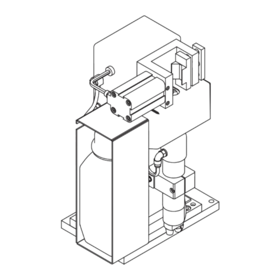
Page 30: Robacta Reamer V Easy, Robacta Reamer V Easy Han6P J Control Elements, Connections And Mechan- Ical Components
Robacta Reamer V Easy, Robacta Reamer V Easy Han6P J control elements, connections and me- chanical components Robacta Reamer NOTE! V Easy, Robacta Reamer V Easy The control elements, connections and mechanical components are shown on the Han6P J control Robacta Reamer V Easy. - Page 31 Lifting device lifts the cleaning motor and the cleaning cutter when cleaning the inside of the gas nozzle Cleaning motor with parting-agent injection nozzle drives the cleaning cutter Compressed air connection for the wire cutter option Parting-agent injection nozzle applies the parting agent to the inside and front of the gas nozzle (10) Cleaning cutter with internal through hole for the parting-agent injection nozzle...
-
Page 32: Robacta Reamer V Control Elements, Connections And Mechanical Components
Robacta Reamer V control elements, connections and mechanical components Robacta Reamer V control ele- (12) ments, connec- tions and (11) mechanical com- ponents (10) Side view Front view Function Standard I/O connection socket (X1) for a + 24 V DC supply CAUTION! Risk of damage to standard I/O connection (X1) supply due to overcurrent. - Page 33 (11) Gas nozzle clamping device holds the gas nozzle in place during cleaning (12) TCP (ToolCenterPoint) with protective covering Absolute zero position for setting and checking the position of the welding torch (for cleaning purposes) CAUTION! Risk of injury from pointed TCP. The protective covering may only be removed when setting and checking the position of the welding torch.
-
Page 34: Standard I/O Connecting Plug (X1) Pin Assignment For Robot Control (Robacta Reamer V)
Standard I/O connecting plug (X1) pin assignment for robot control (Robacta Reamer V) General CAUTION! Risk of damage to standard I/O connection (X1) supply due to overcurrent. Secure supply against overcurrent with a 500 mA slow-blow fuse. NOTE! To avoid malfunction, keep the cable length between the cleaning device and robot control as short as possible. -
Page 35: Harting Han6P Connecting Plug Pin Assignment (X1) For Robot Control (Robacta Reamer V Easy, Robacta Reamer V Easy Han6P J)
Harting Han6P connecting plug pin assignment (X1) for robot control (Robacta Reamer V Easy, Robacta Reamer V Easy Han6P J) General CAUTION! Risk of damage to Harting Han6P connection (X1) supply due to overcurrent. Secure supply against overcurrent with a 500 mA slow-blow fuse. -
Page 37: Installation And Commissioning
Installation and commissioning... -
Page 39: Safety
Safety Safety Observe the following safety rules for all work described in the "Installation and start-up" section. WARNING! Incorrect operation or poorly executed work can cause serious injury or damage. All activities described in these Operating Instructions may only be carried out by trained and qualified personnel. -
Page 40: Ensuring That The Cleaning Device Is Depressurised
Ensure that the cleaning device has been disconnected from the compressed air sup- Robacta Reamer V Easy and Robacta Reamer V Easy Han6P J: Briefly turn the "Cleaning" screw on the cleaning device 90° to the right, then turn it... -
Page 41: Before Commissioning
Before commissioning Proper use The cleaning device is to be used exclusively for cleaning Fronius robot welding torches, especially the gas nozzle and its interior, in automatic mode and within the scope of the technical data. Any use above and beyond this purpose is deemed improper. The manu- facturer shall not be held liable for any damage arising from such usage. -
Page 42: Screwing The Robacta Reamer V Easy, Robacta Reamer V To The Underlying Surface
Screwing the Robacta Reamer V Easy, Robacta Reamer V to the underlying surface Screwing the NOTE! cleaning device and installation Different fixings may be required to set up the installation stand depending on the stand to the un- type of underlying surface (foundation). - Page 43 NOTE! Place the cleaning device and the spatter tray retainer on a level, firm and vibration- free surface (foundation). Position the cleaning device in such a way that the distance the robot has to travel to the cleaning position is as short as possible.
-
Page 44: Screwing The Robacta Reamer V Easy Han6P J To The Underlying Surface
Screwing the Robacta Reamer V Easy Han6P J to the underlying surface Screwing the ad- NOTE! justed cleaning device and instal- Different fixings may be required to set up the installation stand depending on the lation stand to the type of underlying surface (foundation). -
Page 46: Torch Cleaning Position
Torch cleaning position Welding torch cleaning position NOTE! The welding torch cleaning position is shown on the Robacta Reamer V as an example. The welding torch cleaning position is the same for all Robacta Reamer V cleaning devices. -
Page 47: Adjust Gas Nozzle Clamping Device
CAUTION! nozzle clamping device Robacta Reamer V Easy Han6P J only: risk of damage to the cleaning device and the welding torch if the gas nozzle clamp- ing device is not properly adjusted. ► The gas nozzle clamping device must not be altered when using gas nozzles with an outer diameter of 25 mm (0.98 inch) - the gas nozzle clamping device has already been... -
Page 48: Fitting The Cleaning Cutter
Fitting the cleaning cutter General NOTE! The cleaning cutter is fitted in the same way for all Robacta Reamer V cleaning de- vices. Fitting the clean- CAUTION! ing cutter A cleaning cutter that has become very hot through use can cause severe burns. Before handling cleaning cutters, allow cleaning cutter to cool to room temperature (+25°C, +77 °F). -
Page 49: Adjusting The Lifting Device
Adjusting the lifting device Adjusting the lift- NOTE! ing device The lifting device is adjusted in the same way for all Robacta Reamer V cleaning de- vices. Remove the protective covering (1) Remove the gas nozzle from the torch neck Loosen the screw (2) on the lifting de- vice Ensure that the lifting device (3) is in its... -
Page 50: Installing A Mechanically Or Electrically-Controlled Wire Cutter On The Robacta Reamer V Easy
Installing a mechanically or electrically-controlled wire cutter on the Robacta Reamer V Easy Installing the me- chanically con- NOTE! trolled wire cutter Use the fixings supplied with the wire cutter Use screws and washers to fit the wire cutter to the cleaning device... -
Page 51: Installing The Electrically-Controlled Wire Cutter
NOTE! Route the compressed air hose for the wire cutter behind the cleaning device Installing the electrically-con- NOTE! trolled wire cutter Use the fixings supplied with the wire cutter NOTE! The wire cutter must be controlled elec- trically by the robot control... -
Page 52: Installing A Mechanically Or Electrically-Controlled Wire Cutter On The Robacta Reamer V
Installing a mechanically or electrically-controlled wire cutter on the Robacta Reamer V Installing the me- chanically con- NOTE! trolled wire cutter Use the fixings supplied with the wire cutter NOTE! Use the fixings supplied with the wire cutter... -
Page 53: Installing The Electrically-Controlled Wire Cutter
Installing the electrically-con- NOTE! trolled wire cutter Use the fixings supplied with the wire cutter NOTE! The wire cutter is controlled electrically by the robot control... -
Page 54: Installing The Adjusted Wire Cutter
Installing the adjusted wire cutter Fitting mounting NOTE! plates for the wire cutter Use the fixings supplied with the mounting plates to fasten the mounting plates. Installing the ad- justed wire cutter... - Page 55 NOTE! Use the fixings supplied with the wire cutter NOTE! The wire cutter must be controlled elec- trically by the robot control...
-
Page 56: Wire Cutter Function
Wire cutter function Maximum wire di- Wire electrodes with a diameter of up to 1.6 mm (0.063 in.) can be cut with an electrically ameter or mechanically controlled wire cutter. How the mechani- If a torch neck pushes the valve lever (1) to cally-controlled the side by more than 15°... -
Page 57: Installing The Compressed Air Supply
Installing the compressed air supply Establishing the To establish the compressed air supply: compressed air Depressurise the compressed air supply line of the cleaning device and ensure that it supply for the remains depressurised for the duration of the following work on the device cleaning device, Screw the supplied compressed air relief valve into the compressed air connection on function of the... -
Page 58: Starting Up The Parting Agent Nebuliser
Starting up the parting agent nebuliser Fill parting agent NOTE! container (1 litre) and connect to Only use "Robacta Reamer" parting agent (item number 42,0411,8042) supplied by the cleaning de- the manufacturer. vice The composition of the manufacturer's parting agent is designed specifically for the clean- ing device. -
Page 59: Adjusting The Parting Agent Nebuliser Spray Amount
2 2 2 2 2 2 * Option (long parting agent hose) Adjusting the NOTE! parting agent nebuliser spray To ensure that the spray amount is adjusted properly, the welding torch must be in amount the cleaning position. Establish a compressed air supply to the cleaning device Connect the cleaning device to the robot control Start the spraying process using the robot control and check that sufficient spray is be- ing applied... - Page 60 If the spray amount is not sufficient, increase it as required by adjusting the spray time using the robot control - a spray time of ~ 0.7 seconds is recommended or by using the parting agent adjuster - see figure below Finely adjusting the spray amount on parting agent ad- juster...
-
Page 61: Using The Fill-Level Control Sensor
Using the fill-level control sensor General The fill-level control sensor emits a signal once the fill level in the parting agent container falls below a specified level. Controls and indi- Function cators on the sen- 'OUT OFF' button for programming the sensor 'OUT ON' button for programming the sensor indicates the sensor operating sta-... -
Page 62: Fitting The Fill-Level Control Sensor
Fitting the fill-lev- el control sensor NOTE! First press the upper part of the sensor into the installation adapter as shown - the sockets (1) on the installation adap- ter must fit into the recesses (2) in the sensor. When the upper part of the sensor is pro- perly lined up in the installation adapter, press the sensor fully into the installation adapter - the latch (3) on the installation ad-... -
Page 63: Calibrating The Empty State
Calibrating the Drain the parting agent container until empty state the parting agent level is at least 20 mm (0.787 in.) below the sensor Establish a power supply to the sensor 20 mm (0.79 in.) Press the "OUT OFF" button for bet- ween 2 and 6 seconds The LED on the sensor flashes slowly... -
Page 64: Locking/Unlocking The Fill-Level Control Sensor
Press the "OUT OFF" button for at least 6 seconds The sensor LED flashes slowly at first, then more rapidly after 6 se- conds After releasing the "OUT OFF" > 6 s button the LED goes out - the sen- sor has detected a high fluid level Locking/unlock- ing the fill-level... -
Page 65: Separating Gnd For Actuators And Sensors (Robacta Reamer V Only)
Separating GND for actuators and sensors (Robacta Reamer V only) General NOTE! The separate GND supply for actuators and sensors is only available for devices purchased after 01/01/2017. Separating GND NOTE! for actuators and sensors (Robac- Once the cable clip has been removed from the terminal strip, pin 15 becomes avail- ta Reamer V) able on the standard I/O connecting plug (X1) as GND for sensors and pin 2 as GND for actuators. -
Page 66: Separating Gnd For Actuators And Sensors (Electrically Controlled Wire Cutter On The Robacta Reamer V)
Separating GND NOTE! for actuators and sensors (electri- After reconnecting the cables, the actuators and sensors of the wire cutter are sup- cally controlled plied separately with GND. wire cutter on the Robacta Reamer... -
Page 67: Checking The Robacta Reamer V Easy And Robacta Reamer V Easy Han6P J Functions
Checking the Robacta Reamer V Easy and Robacta Reamer V Easy Han6P J functions General NOTE! Before starting the automatic cleaning process, the functions of the cleaning device must be checked manually. NOTE! To ensure that the functions are checked properly, the welding torch must be in the cleaning position. - Page 68 If necessary, only activate the spray device: The following must be checked when the function is being performed: parting agent emerging from the par- ting-agent injection nozzle Spraying in parting agent...
-
Page 69: Manually Checking Robacta Reamer V Functions
Manually checking Robacta Reamer V functions General NOTE! Before starting the automatic cleaning process, the functions of the cleaning device must be checked manually. NOTE! To ensure that the functions are checked properly, the welding torch must be in the cleaning position. - Page 70 Lifting device up/down Deactivating the function The following must be checked when the function is being performed: parting agent emerging Spraying in parting agent Deactivating the function...
-
Page 71: Starting Up The Cleaning Device
Starting up the cleaning device Prerequisites for The following requirements must be met before the cleaning device is started up: start-up If present, the cleaning device installation stand is screwed to the underlying surface The cleaning device is screwed to the underlying surface The gas nozzle clamping device has been adjusted - not on the Robacta Reamer V Easy Han6P J and if a gas nozzle with an outer diameter of 25 mm ( 0,98 inch) is used. -
Page 72: Cleaning Programme
Cleaning programme Safety CAUTION! Risk of damage. Do not start in automated mode until the cleaning device has been properly installed and started up. NOTE! Not coating the interior of the welding torch may result in permanent soiling of the torch when welding begins. -
Page 73: Cleaning Program On The Robacta Reamer V Easy And Robacta Reamer V Easy Han6P J
Cleaning program on the Robacta Reamer V Easy and Robacta Reamer V Easy Han6P J... -
Page 76: Cleaning Program On The Robacta Reamer
Cleaning program on the Robacta Reamer V... -
Page 80: Cleaning Signal Waveform On The Robacta Reamer V Easy And Robacta Reamer V Easy Han6P J
Cleaning signal waveform on the Robacta Reamer V Easy and Robacta Reamer V Easy Han6P J Signal inputs Start cleaning (clamp gas nozzle, cleaning motor on, cleaning motor off, spray parting agent): Signal outputs Gas nozzle free:... -
Page 81: Robacta Reamer V Cleaning Signal Waveform
Robacta Reamer V cleaning signal waveform Signal inputs Clamp gas nozzle/cleaning motor on: Cleaning motor up: Spray in parting agent: Signal outputs Gas nozzle free: Gas nozzle clamped: Cleaning motor turning (impulse signal): Cleaning motor lowered: Cleaning motor raised:... -
Page 82: Signal Waveform: Optional Wire Cutter (Inputs And Outputs)
Signal waveform: Cut wire electrode input signal: optional wire cut- ter (inputs and outputs) Wire cutter open output signal: Wire cutter closed output signal: Signals not de- Parting agent level OK: fined using time... -
Page 83: Care, Maintenance And Disposal
Care, maintenance and disposal... -
Page 85: Care, Maintenance And Disposal
Care, maintenance and disposal General The cleaning device generally needs no maintenance. However, to keep the cleaning de- vice in good working condition for years to come, several points on care and maintenance must be observed. Before each start- Check fill level in parting agent container and top up if necessary Check fill level in parting agent spatter tray and empty if necessary Check cleaning cutter for wear and replace if necessary Empty the cleaning device spatter tray... -
Page 87: Troubleshooting
Troubleshooting... -
Page 89: Safety
Safety Safety Observe the following safety rules for all work described in the "Troubleshooting" section. WARNING! Incorrect operation or poorly executed work can cause serious injury or damage. All activities described in these Operating Instructions may only be carried out by trained and qualified personnel. -
Page 90: Ensuring That The Cleaning Device Is Depressurised
Ensure that the cleaning device has been disconnected from the compressed air sup- Robacta Reamer V Easy and Robacta Reamer V Easy Han6P J: Briefly turn the "Cleaning" screw on the cleaning device 90° to the right, then turn it... -
Page 91: Troubleshooting
Troubleshooting Errors in program Parting agent does not spray sequence Parting agent container is full Cause: Not enough spray Remedy: Adjust spray amount (spray time or parting agent adjuster) Cause: Parting agent hose suction filter in the parting agent container is soiled Remedy: Clean the parting agent hose suction filter with compressed air (see "Starting up the parting agent nebuliser") - Page 92 Lifting device is not moving up or down Cause: Compressed air relief valve closed Remedy: Open compressed air relief valve Cause: No signal from robot Remedy: Check robot program Cause: Mechanical fault on solenoid valve Remedy: Contact After-Sales Service (arrange for solenoid valve to be replaced) Cause: Choke valve not adjustable, or faulty Remedy:...
-
Page 93: Technical Data
Technical data... -
Page 95: Technical Data
Technical data Robacta Reamer Supply voltage + 24 V DC V Easy Nominal output 2.4 W Nominal pressure 6 bar 86.99 psi Air consumption 420 l/min 443.81 qt./min Harting Han6P (X1) Input: + 24 V DC/ max. 100 mA Output: + 24 V DC / max. 30 mA Cleaning time 3.0 - 5.0 s Total cycle time... -
Page 96: Robacta Reamer V
7.28 x 9.65 x 13.86 in. Weight 11 kg (without parting agent, wire cutter and mounting 24.25 lb. plates for the wire cutter / Robacta Reamer V Easy Han6P J) Robacta Reamer Supply voltage + 24 V DC Nominal output 7.2 W... -
Page 97: Appendix
Appendix... -
Page 98: Spare Parts List: Robacta Reamer V Easy
Spare parts list: Robacta Reamer V Easy... -
Page 99: Spare Parts List: Robacta Reamer V
Spare parts list: Robacta Reamer V... -
Page 100: Spare Parts List: Robacta Reamer V Easy Han6P J
Spare parts list: Robacta Reamer V Easy Han6P J Robacta Reamer V Easy Han6P J 44,0450,1951 Front Back Han6P J... -
Page 101: Circuit Diagrams: Robacta Reamer V
Circuit diagrams: Robacta Reamer V... -
Page 102: Circuit Diagrams: Robacta Reamer V Easy, Easy Han6P, Easy Han6P J
Circuit diagrams: Robacta Reamer V Easy, Easy Han6P, Easy Han6P J Engschalter „Gasdüse frei“ Limit switch „Gas nozzle free“ 24 V DC max. 150 mA 24 V DC max. 105 mA... -
Page 103: Robacta Reamer V Easy And Easy Han6P J Pneumatic Diagram
Robacta Reamer V Easy and Easy Han6P J pneumat- ic diagram... -
Page 104: Robacta Reamer V Pneumatic Diagram
Robacta Reamer V pneumatic diagram... -
Page 105: Declarations Of Conformity
Produkt: responsibility that the following que le produit suivant: product: Robacta Reamer V easy Robacta Reamer V easy Robacta Reamer V easy Gasdüsenreinigungsgerät Gas nozzle cleaner Appareil de nettoyage de buses gaz auf das sich diese Erklärung... - Page 106 (technische Dokumentation) (technical documents) (technique documentation) Ing. Josef Feichtinger Ing. Josef Feichtinger Ing. Josef Feichtinger Günter Fronius Straße 1 Günter Fronius Straße 1 Günter Fronius Straße 1 A - 4600 Wels-Thalheim A - 4600 Wels-Thalheim A - 4600 Wels-Thalheim 2016 ppa.
- Page 108 FRONIUS INTERNATIONAL GMBH Froniusstraße 1, A-4643 Pettenbach, Austria E-Mail: sales@fronius.com www.fronius.com Under www.fronius.com/contact you will find the addresses of all Fronius Sales & Service Partners and locations...
Need help?
Do you have a question about the Robacta Reamer V Easy and is the answer not in the manual?
Questions and answers