Heartland VALUE Series Assembly Manual
Hide thumbs
Also See for VALUE Series:
- Assembly manual (85 pages) ,
- Assembly manual (33 pages) ,
- Assembly manual (71 pages)
Advertisement
Quick Links
For questions on assembly or for general inquiries, you may contact us in the following ways:
Call a Recruiter Today! 734-365-7000
Flexible schedule
*based on number of completed installations
Call Us First!
DO NOT RETURN TO STORE.
Call customer service: 1-877-743-3400
AVOID THE WAIT!
visit us online at
help.backyardproducts.com
Submit a help request
Answers to frequently asked questions
Live chat with an agent
Did you enjoy building your shed?
JOIN OUR TEAM
AND MAKE UP TO $1,500/WEEK*
No selling,
just building
Bonus incentives
available
16917
Advertisement

Subscribe to Our Youtube Channel
Related Manuals for Heartland VALUE Series


Summary of Contents for Heartland VALUE Series
- Page 1 16917 Call Us First! DO NOT RETURN TO STORE. For questions on assembly or for general inquiries, you may contact us in the following ways: Call customer service: 1-877-743-3400 AVOID THE WAIT! visit us online at help.backyardproducts.com Submit a help request Answers to frequently asked questions Live chat with an agent Did you enjoy building your shed?
- Page 2 Win $500 A new winner is selected every 2 months. Review your product for the chance to win a $500 Visa Gift Card. Open camera. How to Enter: Aim. Tap. Scan Click Find your product. Submit your review. QR code above. ‘write a review’...
-
Page 3: Assembly Manual
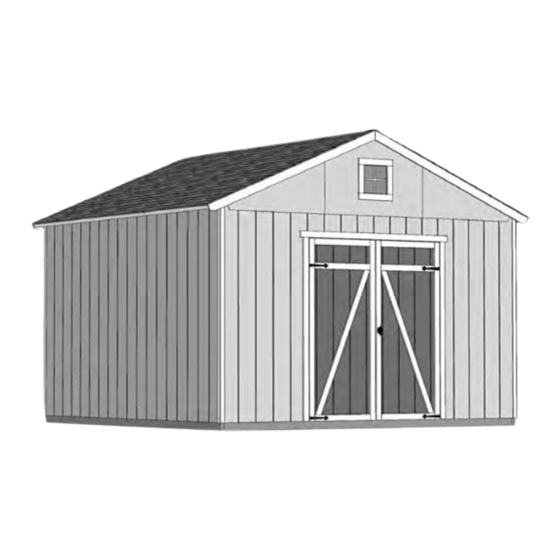
16917 01/18/2022 ASSEMBLY MANUAL VALUE SERIES CLASSIC 12' x 12' (365,8 x 365,8 cm) BUILDING SIZE ACTUAL FLOOR SIZE 12' x 12' (365,8 x 365,8 cm) 12' x 12' (365,8 x 365,8 cm) BASE MODEL +1: 12' x 4' Extender... - Page 4 TOOLS Required Optional ❑ Phillips ❑ Tool Belt/ ❑ Utility Knife Screwdriver Nail Pouch ❑ Shingle Blades ❑ Drill / Driver ❑ Tin Snips ❑ 3/8" Drill Bit ❑ Caulk Gun (for drip edge) ❑ #2 Philips Drive Bit ❑ Chalk Line ❑...
-
Page 5: Additional Materials
ADDITIONAL MATERIALS FOUNDATION OR FLOOR MATERIALS • This shed does not include any floor or leveling materials. • See the FLOOR LEVELING section on page 10 for recommended methods and suggested materials to properly level your floor, as this will vary depending on your specific site. REINFORCED WOOD FLOOR FRAME (OPTIONAL) IMPORTANT! Depending on your specific use you may want to construct a heavy duty floor frame by adding additional floor joists (shown below as shaded). -
Page 6: Optional Materials
ADDITIONAL MATERIALS COMPLETING YOUR SHED You will need these additional materials: 12x12' 12x16' 12x20' 12x24' 12x12' 12x16' 12x20' 12x24' Paint for trim/Quart 3-TAB SHINGLES (Bundles)..Use 100% acrylic latex exterior paint. PAINT FOR SIDING (Gallons)..Caulk Tubes ... Use 100% acrylic latex exterior paint. Use acrylic paintable (2) coats recommended. - Page 7 PARTS IDENTIFICATION AND SIZES Double letter part identification WOOD SIZE CONVERSION CHART Nominal Board Size Actual Size is stamped on some parts. 2 x 4 ....1-1/2" x 3-1/2" (3,8 x 8,9 cm) 1 x 4 ....3/4" x 3-1/2" (1,9 x 8,9 cm) •...
- Page 8 PANEL & DOORS PARTS LIST NOTE: Panel parts are not stamped with part identification. 3/8 x 48 x 84" 3/8 x 23-7/8 x 84" (1 x 121,9 x 213,4 cm) (1 x 60,6 x 213,4 cm) ROOF PANELS Roof panels are 7/16" (1,1 cm) thick. 48"...
- Page 9 NAIL BOXES (Shown Actual Size) 3" (7,6 cm) BOXES 2" (5,1 cm) BOXES FASTENER/HARDWARE BAG (Shown Actual Size) 2" (5,1 cm) x155 1-1/2" (3,8 cm) 3" (7,6 cm) 2" (5,1 cm) NOTE: 1-1/4" (3,2 cm) If you are using a nail gun, nails may be used where screws are 3/4"...
- Page 10 GABLE EXTENDER KIT PARTS LIST Inventory your parts before you begin. We suggest sorting parts by the category they are listed in. Part identification WOOD SIZE CONVERSION CHART is stamped on some parts. Nominal Board Size Actual Size 2 x 4 ....1-1/2" x 3-1/2" (3,8 x 8,9 cm) 1 x 4 ....3/4"...
- Page 11 CONCRETE FOUNDATION If you choose to install your kit on a concrete slab refer to the diagram below. Attach the sill plates on the foundaton as shown, and continue on to page 14. Treated Sill Plate Caulk between sill plate and concrete.
- Page 12 OPTIONAL WOOD FRAME FLOOR LEVELING OPTIONS There are multiple ways to level your floor frame. Our recommended leveling method is shown below. Leveling materials are not included in this kit. PREFERRED METHOD - 4x4 TREATED RUNNERS (Typical for 12' x 12' Kit) Measurements to centers of 4x4's.
- Page 13 LEVELING & SQUARING THE FLOOR FRAME (Not Included) LEVEL AND SQUARE FLOOR FRAME Before attaching floor decking, it is important to level and square the floor frame. A level and square floor frame is required to correctly construct your shed. See page 10 for the preferred foor leveling method.
- Page 14 IMPORTANT! I M P O R T A N T ! NOTE: 12' x 12' Gable shown standard throughout manual Ensure the foor frame is level after installing foor panels. Re-level if needed. • The foor should used as a stable work surface for wall construction. •...
- Page 15 WALL INDEX IMPORTANT! Build door header before building any walls (see page 14). 12' x 12' 12' x 16' After assembling the walls for your 12' x 12' shed, After assembling the walls for your 12' x 16' shed, go to page 28 for wall installation. go to page 33 for wall installation.
-
Page 16: Parts Required
DOOR HEADER Assemble this door header before building any walls! PARTS REQUIRED: 3" (7,6 cm) 2 x 4 x 67" (5,1 x 10,2 x 170,2 cm) 7/16 x 3-1/4 x 66-3/4" (1,1 x 8,3 x 170,2 cm) BEGIN Place (1) AM and OSB end-to-end on flat surface, flush in middle. Center OSB on top of AM. - Page 17 WALL PANEL INSTALLATION HINTS & EXAMPLES PARTS REQUIRED: 2" (5,1 cm) 2x3" TEMP. SPACER 3/4" GAUGE BLOCK 3/8 x 48 x 84" (1 x 121,9 x 213,4 cm ) Ensure your wall is square by installing one panel and squaring frame. Install all wall panels with the primed side facing up.
- Page 18 GABLE WALL 01 WITH DOOR PARTS REQUIRED: 2 x 4 x 7" (5,1 x 10,2 x 17,8 cm) 3" (7,6 cm) 2 x 4 x 48" (5,1 x 10,2 x 121,9 cm) 3" (7,6 cm) 2 x 4 x 78-1/2" (5,1 x 10,2 x 199,4 cm) 2 x 4 x 96"...
- Page 19 GABLE WALL 01 WITH DOOR PARTS REQUIRED: 3" (7,6 cm) x166 2" (5,1 cm) 23-7/8 x 84" (60,6 x 213,4 cm) Temporary Brace 69" (75,3 cm) Door Stiffener Install the left panel 1-1/2" from the top plate. 1-1/2" Flush (3,8 cm) Use a 2x3 spacer for 3/4"...
- Page 20 12' GABLE WALL 02 PARTS REQUIRED: 3" (7,6 cm) 2 x 4 x 48" (5,1 x 10,2 x 121,9 cm) 2 x 4 x 78-1/2" (5,1 x 10,2 x 199,4 cm) 2 x 4 x 96" (5,1 x 10,2 x 243,8 cm) BEGIN Orient parts on edge on floor as shown.
- Page 21 12' GABLE WALL 02 PARTS REQUIRED: x150 2" (5,1 cm) 48 x 84" 23-7/8" x 84" (121,9 x 213,4 cm ) (60,6 x 213,4 cm ) 1-1/2" (3,8 cm) 3/4" BEGIN HERE (1,9 cm) Install 48" x 84" panel 1-1/2" from the top plate.
- Page 22 12' EAVE WALL 03 PARTS REQUIRED: 3" (7,6 cm) 2 x 4 x 44-3/8" (5,1 x 10,2 x 112,7 cm) 2 x 4 x 92-5/8" (5,1 x 10,2 x 235 cm) 2 x 4 x 68-1/2" (5,1 x 10,2 x 174 cm) 2 x 4 x 78-1/2"...
- Page 23 12' EAVE WALL 03 PARTS REQUIRED: x240 2" (5,1 cm) 48 x 84" (121,9 x 213,4 cm ) 3/4" BEGIN HERE (1,9 cm) 3-1/2" Install 48" x 84" panel (8,9 cm) 1-1/2" from the top plate. 1-1/2" (3,8 cm) Use a 2x3 spacer for consistent measurement.
- Page 24 16' EAVE WALL 04 PARTS REQUIRED: 3" (7,6 cm) 2 x 4 x 44-3/8" (5,1 x 10,2 x 112,7 cm) 2 x 4 x 78-1/2" (5,1 x 10,2 x 199,4 cm) 2 x 4 x 48" (5,1 x 10,2 x 121,9 cm) 2 x 4 x 92-5/8"...
- Page 25 16' EAVE WALL 04 PARTS REQUIRED: x340 2" (5,1 cm) 48 x 84" (121,9 x 213,4 cm ) Install (1) 48" x 84" panel 1-1/2" from 3/4" BEGIN HERE (1,9 cm) the top plate. 1-1/2" (3,8 cm) Use a 2x3 spacer for consistent 6"...
- Page 26 20' EAVE WALL 05 PARTS REQUIRED: 3" (7,6 cm) 2 x 4 x 68-1/2" (5,1 x 10,2 x 174 cm) 2 x 4 x 44-3/8" (5,1 x 10,2 x 112,7 cm) 2 x 4 x 78-1/2" (5,1 x 10,2 x 199,4 cm) 2 x 4 x 92-5/8"...
- Page 27 20' EAVE WALL 05 PARTS REQUIRED: x440 2" (5,1 cm) 48 x 84" (121,9 x 213,4 cm ) Install (1) 48" x 84" panel 1-1/2" from the top plate. Use a 2x3 spacer for consistent measurement. Secure panel with 2" nails spaced 6" apart on edges and 12" inside panel. Note the panel lip-edge/square edge orientation.
- Page 28 24' EAVE WALL 06 PARTS REQUIRED: x112 3" (7,6 cm) 2 x 4 x 68-1/2" (5,1 x 10,2 x 174 cm) 2 x 4 x 44-3/8" (5,1 x 10,2 x 112,7 cm) 2 x 4 x 78-1/2" (5,1 x 10,2 x 199,4 cm) 2 x 4 x 48"...
- Page 29 24' EAVE WALL 06 PARTS REQUIRED: x540 2" (5,1 cm) 48 x 84" (121,9 x 213,4 cm ) Install (1) 48" x 84" panel 1-1/2" from the top plate. Use a 2x3 spacer for consistent measurement. Secure panel with 2" nails spaced 6" apart on edges and 12" inside panel. Note the panel lip-edge/square edge orientation.
- Page 30 12' GABLE WALL 02 INSTALLATION PARTS REQUIRED: 3" (7,6 cm) 69" (175,3 cm) Door Stiffener 3" (7,6 cm) 2" (5,1 cm) 1-1/2" BEGIN (3,8 cm) Center 12' gable wall on the 144" (365,8 cm) floor dimension. 1-1/2" (3,8 cm) overlap is to the top. Use OO as a temporary brace.
- Page 31 1st 12' EAVE WALL INSTALLATION PARTS REQUIRED 2" (5,1 cm) 3" (7,6 cm) 2" (5,1 cm) 1-1/2" (3,8 cm) 3" (7,6 cm) BEGIN Fig. B Place 12' eave wall centered on floor. 1-1/2" (3,8 cm) overlap is to the top. 2"...
- Page 32 2nd 12' EAVE WALL INSTALLATION PARTS REQUIRED: 2" (5,1 cm) 3" (7,6 cm) 2" (5,1 cm) 3" (7,6 cm) 1-1/2" (3,8 cm) Fig. B BEGIN 1-1/2" (3,8 cm) Place 2nd 12' eave wall centered on floor 1-1/2" (3,8 cm) overlap is to the top. 2"...
- Page 33 12' GABLE WALL WITH DOOR INSTALLATION PARTS REQUIRED 2" (5,1 cm) 3" (7,6 cm) 2" (5,1 cm) 3" (7,6 cm) 1-1/2" (3,8 cm) Fig. B BEGIN 2" (5,1 cm) Place 12' gable wall on floor, centered Screw between installed walls. Secure wall with 2"...
- Page 34 12' x 12' WALL DOUBLERS INSTALLATION PARTS REQUIRED: 3" (7,6 cm) 2 x 4 x 48" (5,1 x 10,2 x 121,9 cm) 2 x 4 x 44-3/8" (5,1 x 10,2 x 112,7 cm) 3" (7,6 cm) 2 x 4 x 92-5/8" (5,1 x 10,2 x 235 cm) 2 x 4 x 96"...
- Page 35 12' GABLE WALL 02 INSTALLATION PARTS REQUIRED: 3" (7,6 cm) 69" (175,3 cm) Door Stiffener 3" (7,6 cm) 2" (5,1 cm) 1-1/2" BEGIN (3,8 cm) Center 12' wall on the 120" (304,8 cm) floor dimension. 1-1/2" (3,8 cm) overlap is to the top. Use OO as a temporary brace.
- Page 36 1st 16' EAVE WALL INSTALLATION PARTS REQUIRED 2" (5,1 cm) 3" (7,6 cm) Temporary Brace 1-1/2" (3,8 cm) 2 x 4 x 92-5/8" (5,1 x 10,2 x 235 cm) 2" (5,1 cm) 3" (7,6 cm) Fig. B BEGIN Place 1st 16' eave wall centered on floor. 1-1/2"...
- Page 37 2nd 16' EAVE WALL INSTALLATION PARTS REQUIRED: 3" (7,6 cm) 2" (5,1 cm) 3" (7,6 cm) Temporary Brace 2 x 4 x 92-5/8" (5,1 x 10,2 x 235 cm) 2" (5,1 cm) 1-1/2" BEGIN (3,8 cm) 3" (7,6 cm) Screws Place 2nd 16' wall centered on floor.
- Page 38 2nd 16' EAVE WALL INSTALLATION PARTS REQUIRED: 1-1/2" (3,8 cm) 3" (7,6 cm) 3" (7,6 cm) Screw Fig. D 6" (15,2 cm) Nail 16' wall panel to 12' wall stud with 1-1/2" nails spaced 6" apart. 1-1/2" (3,8 cm) Nails Secure gable wall top plate with (1) 3"...
- Page 39 12' GABLE WALL WITH DOOR INSTALLATION PARTS REQUIRED 2" (5,1 cm) 3" (7,6 cm) 2" (5,1 cm) 3" (7,6 cm) 1-1/2" (3,8 cm) Fig. B BEGIN 2" (5,1 cm) Place 12' gable wall on floor, centered Screw between installed walls. Secure wall with 2"...
- Page 40 12' x 16' WALL DOUBLERS INSTALLATION PARTS REQUIRED: 3" (7,6 cm) 2 x 4 x 48" (5,1 x 10,2 x 121,9 cm) 2 x 4 x 44-3/8" (5,1 x 10,2 x 112,7 cm) 3" (7,6 cm) 2 x 4 x 92-5/8" (5,1 x 10,2 x 235 cm) 2 x 4 x 96"...
- Page 41 12' GABLE WALL 02 INSTALLATION PARTS REQUIRED: 3" (7,6 cm) 69" (175,3 cm) Door Stiffener 3" (7,6 cm) 2" (5,1 cm) 1-1/2" BEGIN (3,8 cm) Center 12' wall on the 120" (304,8 cm) floor dimension. 1-1/2" (3,8 cm) overlap is to the top. Use OO as a temporary brace.
- Page 42 1st 20' EAVE WALL INSTALLATION PARTS REQUIRED 2" (5,1 cm) 3" (7,6 cm) Temporary Brace 1-1/2" (3,8 cm) 2 x 4 x 92-5/8" (5,1 x 10,2 x 235 cm) 2" (5,1 cm) 3" (7,6 cm) BEGIN Fig. B Place 1st 20' eave wall centered on floor. 2"...
- Page 43 2nd 20' EAVE WALL INSTALLATION PARTS REQUIRED: 2" (5,1 cm) 3" (7,6 cm) 2" (5,1 cm) 3" (7,6 cm) Temporary Brace 2 x 4 x 92-5/8" (5,1 x 10,2 x 235 cm) BEGIN 3" (7,6 cm) 2" (5,1 cm) Place 2nd 20' wall centered on floor. Screw Screws 1-1/2"...
- Page 44 2nd 20' EAVE WALL INSTALLATION PARTS REQUIRED: 3" (7,6 cm) 1-1/2" (3,8 cm) Secure 20' wall panel to 12' wall stud with 1-1/2" nails spaced 6" apart. 3" (7,6 cm) Screw Fig. D Secure wall top plate with (1) 3" screw at the corner at an angle as shown (Fig.
- Page 45 12' GABLE WALL WITH DOOR INSTALLATION PARTS REQUIRED 2" (5,1 cm) 3" (7,6 cm) 2" (5,1 cm) 3" (7,6 cm) 1-1/2" (3,8 cm) Fig. B BEGIN 2" (5,1 cm) Place 12' gable wall on floor, centered Screw between installed walls. Secure wall with 2"...
- Page 46 12' x 20' WALL DOUBLERS INSTALLATION PARTS REQUIRED: PARTS REQUIRED: 3" (7,6 cm) 2 x 4 x 48" (5,1 x 10,2 x 121,9 cm) 2 x 4 x 44-3/8" (5,1 x 10,2 x 112,7 cm) 3" (7,6 cm) 2 x 4 x 92-5/8" (5,1 x 10,2 x 235 cm) 2 x 4 x 96"...
- Page 47 12' GABLE WALL 02 INSTALLATION PARTS REQUIRED: 3" (7,6 cm) 69" (175,3 cm) Door Stiffener 3" (7,6 cm) 2" (5,1 cm) 1-1/2" BEGIN (3,8 cm) Center 12' wall on the 120" (304,8 cm) floor dimension. 1-1/2" (3,8 cm) overlap is to the top. Use OO as a temporary brace.
- Page 48 1st 24' EAVE WALL INSTALLATION PARTS REQUIRED 2" (5,1 cm) 3" (7,6 cm) Temporary Brace 1-1/2" (3,8 cm) 2 x 4 x 92-5/8" (5,1 x 10,2 x 235 cm) 2" (5,1 cm) 3" (7,6 cm) Fig. B BEGIN Place 1st 24' eave wall centered on floor.
- Page 49 2nd 24' EAVE WALL INSTALLATION PARTS REQUIRED: 2" (5,1 cm) 3" (7,6 cm) 2" (5,1 cm) 3" (7,6 cm) Temporary Brace 2 x 4 x 92-5/8" (5,1 x 10,2 x 235 cm) BEGIN Place 2nd 24' wall centered 3" (7,6 cm) on floor.
- Page 50 2nd 24' EAVE WALL INSTALLATION PARTS REQUIRED: 3" (7,6 cm) 1-1/2" (3,8 cm) Secure 24' wall panel to 12' wall stud with 1-1/2" nails spaced 6" apart. 3" (7,6 cm) Fig. D Screw Secure wall top plate with (1) 3" screw at the corner at an angle as shown (Fig.
- Page 51 12' GABLE WALL WITH DOOR INSTALLATION PARTS REQUIRED 2" (5,1 cm) 3" (7,6 cm) 2" (5,1 cm) 3" (7,6 cm) 1-1/2" (3,8 cm) Fig. B BEGIN 2" (5,1 cm) Place 12' gable wall on floor, centered Screw between installed walls. Secure wall with 2"...
- Page 52 12' x 24' WALL DOUBLERS INSTALLATION PARTS REQUIRED: PARTS REQUIRED: 2 x 4 x 44-3/8" (5,1 x 10,2 x 112,7 cm) 3" (7,6 cm) 2 x 4 x 48" (5,1 x 10,2 x 121,9 cm) 3" (7,6 cm) 2 x 4 x 92-5/8" (5,1 x 10,2 x 235 cm) 2 x 4 x 96"...
- Page 53 12x12' 12x16' 12x20' 12x24' RAFTERS PARTS REQUIRED: 3" (7,6 cm) 6 x 24" (15,2 x 60,9 cm) x1 RL Temporary Support 2 x 4 x 24" (5,1 x 10,2 x 61 cm) 2 x 4 x 77-15/16" (5,1 x 10,2 x 198 cm) x144 x192 x240...
- Page 54 RAFTER INSTALLATION 12x12' 12x16' PARTS REQUIRED: 2-Gusset 1-Gusset Preassembled Preassembled 3" (7,6 cm) BEGIN Align rafters over the wall studs. Check that you have the measurements shown. Secure rafters with (2) 3" screws angled at each end (Fig. A, Fig. B). Secure rafters on opposite side.
- Page 55 RAFTER INSTALLATION 12x20' 12x24' PARTS REQUIRED: 2-Gusset 1-Gusset Preassembled Preassembled 3" (7,6 cm) BEGIN Align rafters over the wall studs. Check that you have the measurements shown. Secure rafters with (2) 3" screws angled at each end (Fig. A, Fig. B). Secure rafters on opposite side.
- Page 56 GABLE UNITS PARTS REQUIRED: x4 AF 2 x 4 x 18-1/8" (5,1 x 10,2 x 46 cm) 1-1/2" (3,8 cm) Install gable panels with the primed side facing up. BEGIN Place middle panel on (2) AF. Arrange parts to measurements shown. Secure panel with 1-1/2"...
- Page 57 GABLE INSTALLATION PARTS REQUIRED: 3" (7,6 cm) x108 2" (5,1 cm) Preassembled BEGIN Measure 2-9/16" (6,5 cm) down from top plate doubler and mark at each side as shown. Set gable unit on top plate. Fasten with (1) 2" nail on each side. BE SURE GABLE IS CENTERED ON WALL BEFORE NAILING.
- Page 58 12' x 12' ROOF PANELS PARTS REQUIRED: 2" (5,1 cm) 3/4" GAUGE BLOCK 7/16 x 48 x 96" (1,1 x 121,9 x 243,8 cm) Roof panels may cause serious injury until securely fastened. Note: Install all roof panels with the rough side up (painted grid lines). Flush at peak BEGIN...
- Page 59 12' x 12' ROOF PANELS PARTS REQUIRED: 2" (5,1 cm) 47-7/8 x 48" (121,6 x 121,9 cm) Flush at peak Install a 23-7/8" x 48" roof panel flush to the Fig. B 1/2" installed panel and flush at peak (Fig. B). (1,2 cm) Secure panel with (1) 2"...
- Page 60 12' x 12' ROOF PANELS PARTS REQUIRED: 2" (5,1 cm) 36-1/2" x 96" 36-1/2" x 47-7/8" 3/4" GAUGE (60,692,7 (91,7 x 121,9 cm) BLOCK Next, install 36-1/2" x 47-7/8" and 36-1/2" x 96" roof panels with a 3/4" measurement on the rafter (Fig A) and flush to the installed panels (Fig.
- Page 61 12' x 12' ROOF PANELS PARTS REQUIRED: x168 2" (5,1 cm) Secure all roof panels with 2" nails spaced 6" apart and 12" apart inside panels. 6" (15,2 cm) Repeat all steps to install roof panels on the opposite side. FINISH Your roof panels are now installed.
- Page 62 12' x 16' ROOF PANELS PARTS REQUIRED: 2" (5,1 cm) 3/4" GAUGE BLOCK 48 x 96" (121,9 x 243,8 cm) Roof panels may cause serious injury until securely fastened. Note: Install all roof panels with the rough side up (painted grid lines). Flush at BEGIN peak...
- Page 63 12' x 16' ROOF PANELS PARTS REQUIRED: 2" (5,1 cm) 47-7/8 x 48" (121,6 x 121,9 cm) Flush at 1/2" peak Install first 47-7/8" x 48" roof (1,2 cm) Fig. B panel flush to the installed panel and flush at the peak. Fig.
- Page 64 12' x 16' ROOF PANELS PARTS REQUIRED: 2" (5,1 cm) 3/4" GAUGE BLOCK 36-1/2" x 96" 36-1/2" x 47-7/8" (60,692,7 (91,7 x 121,9 cm) Next, install 36-1/2" x 96" with a 3/4" measurement on the rafter (Fig A), and flush to the installed panels. Secure panel with (1) 2"...
- Page 65 12' x 16' ROOF PANELS PARTS REQUIRED: x236 2" (5,1 cm) Secure all roof panels with 2" nails spaced 6" apart and 12" apart inside panels. 6" (15,2 cm) Repeat all steps to install roof panels on the opposite side. FINISH Your roof panels are now installed.
- Page 66 12' x 20' ROOF PANELS PARTS REQUIRED: 2" (5,1 cm) 3/4" GAUGE BLOCK 48 x 96" (121,9 x 243,8 cm) Roof panels may cause serious injury until securely fastened. Note: Install all roof panels with the rough side up (painted grid lines). Flush at peak BEGIN...
- Page 67 12' x 20' ROOF PANELS PARTS REQUIRED: 2" (5,1 cm) 48 x 96" 47-7/8 x 48" (121,9 x 243,8 cm) (121,6 x 121,9 cm) Flush at 1/2" peak (1,2 cm) Install next 48" x 96" roof panel Fig. B Fig. C flush to the installed panel and flush at the peak.
- Page 68 12' x 20' ROOF PANELS PARTS REQUIRED: 2" (5,1 cm) 3/4" GAUGE 36-1/2" x 96" 36-1/2" x 47-7/8" BLOCK (60,692,7 (91,7 x 121,9 cm) Next, install 36-1/2" x 96" roof panel with a 3/4" measurement on the rafter (Fig A). Secure panel with (1) 2"...
- Page 69 12' x 20' ROOF PANELS PARTS REQUIRED: x268 2" (5,1 cm) Secure all roof panels with 2" nails spaced 6" apart and 12" apart inside panels. 6" (15,2 cm) Repeat all steps to install roof panels on the opposite side. FINISH Your roof panels are now installed.
- Page 70 12' x 24' ROOF PANELS PARTS REQUIRED: 2" (5,1 cm) 3/4" GAUGE BLOCK 48 x 96" (121,9 x 243,8 cm) Roof panels may cause serious injury until securely fastened. Note: Install all roof panels with the rough side up (painted grid lines). BEGIN Flush at peak...
- Page 71 12' x 24' ROOF PANELS PARTS REQUIRED: 2" (5,1 cm) 48 x 96" 47-7/8 x 48" (121,9 x 243,8 cm) (121,6 x 121,9 cm) Flush at 1/2" peak (1,2 cm) Install 2nd 48" x 96" roof panel Fig. B flush to the installed panel, and flush at the peak (Fig.
- Page 72 12' x 24' ROOF PANELS PARTS REQUIRED: 2" (5,1 cm) 3/4" GAUGE BLOCK 36-1/2" x 96" 36-1/2" x 47-7/8" (60,692,7 (91,7 x 121,9 cm) Install (1) 36-1/2" x 96" roof panels with a 3/4" measurement on the rafter at each side (Fig A), and flush to the installed panels.
- Page 73 12' x 24' ROOF PANELS PARTS REQUIRED: x336 2" (5,1 cm) Secure all roof panels with 2" nails spaced 6" apart and 12" apart inside panels. 6" (15,2 cm) Repeat all steps to install roof panels on the opposite side. FINISH Your roof panels are now installed.
- Page 74 GABLE TRIM PARTS REQUIRED: 2" (5,1 cm) 19/32" x 3-1/2" x 84-15/16" (1,5 x 8,9 x 215,7 cm) 19/32" x 3-1/2" x 84-15/16" (1,5 x 8,9 x 215,7 cm) BEGIN Install gable trim CQR and CQL flush to top of roof panel and flush at peak, as shown. Secure trim with 2"...
- Page 75 12' x 12' EAVE TRIM PARTS REQUIRED: 1-1/4" (3,2 cm) 3" (7,6 cm) 2 x 6 x 49-3/4" (5,1 x 15,2 x 126,4 cm) 2 x 6 x 96" (5,1 x 15,2 x 243,8 cm) BEGIN Place VX eave trim flush along edge of roof panel (Fig. A). Screw through roof panel into trim with 1-1/4"...
- Page 76 12' x 16' EAVE TRIM PARTS REQUIRED: 1-1/4" (3,2 cm) 3" (7,6 cm) 2 x 6 x 96" (5,1 x 15,2 x 243,8 cm) 2 x 6 x 48" (5,1 x 15,2 x 121,9 cm) 2 x 6 x 49-3/4" (5,1 x 15,2 x 126,4 cm) BEGIN Place WTC eave trim flush along edge of roof panel (Fig.
- Page 77 12' x 20' EAVE TRIM PARTS REQUIRED: 1-1/4" (3,2 cm) 3" (7,6 cm) 2 x 6 x 49-3/4" (5,1 x 15,2 x 126,4 cm) 2 x 6 x 96" (5,1 x 15,2 x 243,8 cm) BEGIN Place WTC eave trim flush along edge of roof panel (Fig. A) and flush to gable trim. Screw through roof panel into WTC with 1-1/4"...
- Page 78 12' x 24' EAVE TRIM PARTS REQUIRED: 1-1/4" (3,2 cm) 3" (7,6 cm) 2 x 6 x 96" (5,1 x 15,2 x 243,8 cm) 2 x 6 x 48" (5,1 x 15,2 x 121,9 cm) 2 x 6 x 49-3/4" (5,1 x 15,2 x 126,4 cm) BEGIN Place WTC eave trim flush along edge of roof panel (Fig.
- Page 79 CORNER TRIM PARTS REQUIRED: 2" (5,1 cm) 3/8" x 1-3/4" x 83-1/2" (1 x 4,5 x 212.1cm) BEGIN Install gable end 83-1/2" corner trim under gable panel, (Fig. A) and flush to eave wall panel (Fig. B). Secure with 2" finishing nails spaced evenly. Install eave side 83-1/2"...
- Page 80 12x12' 12x16' 12x20' 12x24' COLLAR TIE INSTALLATION PARTS REQUIRED: 2 x 4 x 96" (5,1 x 10,2 x 243,9 cm) 3" (7,6 cm) BEGIN Fig. A Install collar tie to the rafter with (3) 3" nails at each end (Fig. A). Flush to roof panel 3"...
- Page 81 LOFT JOISTS PARTS REQUIRED: 3" (7,6 cm) 2 x 4 x 48" (5,1 x 10,2 x 121,9 cm) 7/16" (11 mm) Drill Bit 2 x 4 x 96" (5,1 x 10,2 x 243,8 cm) ¸ BEGIN Orient parts TP and SP on a flat surface. Hold parts TP and SP flush and aligned.
- Page 82 LOFT JOIST INSTALLATION PARTS REQUIRED: 3" (7,6 cm) 2 x 3 x 48" (5,1 x 7,6 x 121,9 cm) 5-1/2" (14 cm) Hex bolt, 2 washers and locknut 2 x 3 x 96" (5,1 x 7,6 x 243,8 cm) LOFT JOIST ASSEMBLY ¸...
- Page 83 LOFT PANELS PARTS REQUIRED: 2" (5,1 cm) 23-7/8" x 40-7/8" (60,6 x 103,8 cm) 23-7/8" x 96" (60,6 x 244 cm) ¸ BEGIN Install loft panels centered over loft joists and ledger board. Secure with 2" nails spaced 8" (20 cm) apart. NOTE: There will be a gap of approximately 1/2"...
- Page 84 SHELF ASSEMBLY AND INSTALLATION PARTS REQUIRED: 2" (5,1 cm) 3/8 x 8 x 12-1/2" (1 x 20,3 x 31,8 cm) 2 x 3 x10" (5,1 x 7,6 x 25,4 cm) BEGIN Secure AC to shelf panels with (3) 2" nails. Assemble (14) shelf supports as shown;...
-
Page 85: Shelf Installation
SHELF INSTALLATION PARTS REQUIRED: 2" (5,1 cm) 7/16 x 11-7/8 x 96" OSB (1,1 x 30,2 x 243,8 cm) 1 x 4 x 96" (2,5 x 10,2 x 243,8 cm) 7/16 x 11-7/8 x 48" 1 x 4 x 48" (2,5 x 10,2 x 121,9 cm) (1,1 x 30,2 x 121,9 cm) Install shelf panels centered over shelf supports, flush to wall studs and flush at seams. - Page 86 DOORS PARTS REQUIRED: 3" (7,6 cm) 1-1/4" (3,2 cm) 1 x 3 x 5" (2,5 x 7,6 x 12,7 cm) 69" (175,3 cm) Door Stiffener Left Door Right Door BEGIN Place doors on flat surface. 3/8" offset is to top. Look for red (right) and green (left) on hinge board.
- Page 87 DOORS PARTS REQUIRED: 3" (7,6 cm) TEMPORARY SUPPORT 69" (175,3 cm) Door Stiffener Install OO flush under panels. Secure to floor frame with (2) 3" screws (Fig. A) . Mark center of door opening. Fig. A Flush against wall panels (2) 3"...
- Page 88 DOOR STIFFENERS PARTS REQUIRED: 2" (5,1 cm) 69" (175,3 cm) Door Stiffener BEGIN Center OO vertically on the left door in the doorway (Fig. A) overlapping 1" (2,5 cm) along the edge of door (Fig. B). Secure with (7) 2" screws through outside trim into OO. Center OO vertically on the right door in the door opening offset 1"...
- Page 89 DOORS PARTS REQUIRED: 2" (5,1 cm) 3/4" (1,9 cm) 19/32" x 2-1/2" x 26 5/8" (1,5 x 6,3 x 67,6 cm) 3/4" (1,9 cm) Bagged separately/ 64" Metal Threshold 19/32" x 2-1/2" x 62" (1,5 x 6,3 x 157,5 cm) special coating 19/32"...
-
Page 90: Door Hardware
DOOR HARDWARE PARTS REQUIRED: 3/4” (1,9 cm) BEGIN Install decorative hinges in locations shown. Secure with 3/4" screws. 3/4" (1,9 cm) Screws Flush to hinge FINISH Your decorative door hinges are now installed. - Page 91 DOOR HARDWARE PARTS REQUIRED: 5/16" (7,9 mm) Drill Bit 3/4" (1,9 cm) BEGIN Place bolt on OO in open position with bolt end 3/8" (9,5 mm) down from frame. Bolt is open when loop is contacting base (Fig A). Mark and pre-drill holes for screws. Install bolt with screws supplied. Drill 5/16"...
- Page 92 DOOR HARDWARE PARTS REQUIRED: 1-1/2" (3,8 cm) 3/8" (10,9 cm) Drill Bit 1/4" (0,6 cm) Drill Bit Measure and mark location of hole on outside of right door as shown (Fig. A) . Pre-drill hole with 1/4" drill. Re-drill hole with 3/8 " drill. Keep drilled hole square to trim to avoid breaking edge of door stiffener.
- Page 93 HOOK & EYE PARTS REQUIRED: ¸ BEGIN Install hooks in wall and into framing behind (Fig.A). Fig. A Swing door open to locate eye. Hook Install hook into framing, if possible. FINISH You have installed your hook & eyes.
- Page 94 GABLE WINDOW PARTS REQUIRED: 2" (5,1 cm) 3/4" (1,9 cm) 19/32" x 2-1/2" x 12" (1,5 x 6,3 x 30,5 cm) 19/32" x 2-1/2" x 17" (1,6 x 7,6 x 43,2 cm) Window BEGIN Center window in front gable as shown and secure with 3/4" screws Seal back of window with high-quality paintable exterior caulk before installing.
- Page 95 VENT (Not included in kit.) • Follow directions provided by manufacturer and these instructions. 1/2" (13 mm) 16" x 8" BEGIN Locate and mark for two vents in side walls as shown; (1) at top and (1) at bottom. Cut out marked openings. Caulk behind vent flanges.
- Page 96 PAINT & CAULK - NOT INCLUDED - • Use acrylic latex caulk that is paintable. Caulk at all horizontal and vertical seams, between the trim and walls, and all around the door trim. • Use a high quality exterior acrylic latex paint. When painting your building, there are a few key areas that can be easily overlooked that must be painted: •...
- Page 97 SHINGLES - NOT INCLUDED - • Follow directions provided by manufacturer and these instructions. Familiarize yourself with a 3-Tab Shingle. Notch Notch SHINGLE NAIL PATTERN 1/2" 1" Sealing Strip (1,3 cm) 1" (2,5 cm) (2,5 cm) Half A Rain Slot Full Rain Slot NAILS NEVER DRIVE FASTENERS INTO OR ABOVE SEALING STRIPS.
- Page 98 SHINGLES continued... Beginning at front of shed, install first row of shingles with notch at 1" past roof edge or flush with drip edge. Roof Deck FRONT OF BACK OF SHED SHED 1" (2,5 cm) Flush with starter row. Notch - or - Drip Edge Flush with starter row.
- Page 99 SHINGLES continued... Continue installing rows of shingles to the peak. At the peak make sure there is a maximum of 5" or less to the rain slot, as shown below. If shingles overlap at ridge cut to peak with a utility knife. 5"...
- Page 100 SHINGLES - RIDGE CAP • You will finish off the top of the roof with a ridge cap made from shingles. BEGIN Cut shingles in THREE pieces. Hint: Use cut-off pieces first. 2" 2" (5,1 cm) (5,1 cm) 2" 2" 2"...
- Page 101 SHINGLES - RIDGE CAP continued... Continue installing ridge cap to back of roof. Make sure there is 4" between the shingle-color and edge of shingles. 4" (10,2 cm) Trim cap off fush to shingles When you have 4" minimum of shingle color cut one piece to cap your roof. Cut at top of rain slot.
- Page 102 16917 12' x12' Order Form CATEGORY PART DESCRIPTION PART SIZE PART ITEM # BUILDING QTY. PART ID Loft Ledger Board "A" LUM SPF 2X3X96 #2&BTR 12115 2 X 3 Loft Ledger Board "B" 2 X 3 X 48" PLATE Q 48000000000 Shelf Support 2 X 3 X 10"...
- Page 103 LIMITED CONDITIONAL WARRANTY* Backyard Storage Solutions, LLC warrants the following: Every product is warranted from defects in workmanship and manufacturing for 1 year. All accessories, hardware and metal components are warranted for 2 years. All Oriented Strand Board (OSB) is warranted for 2 years Siding and Trim is warranted for 15 years.
Need help?
Do you have a question about the VALUE Series and is the answer not in the manual?
Questions and answers