Advertisement
Quick Links
16660
STOP!
STOP!
Call Us First!
DO NOT RETURN TO STORE.
For immediate help with assembly or product information
call our toll free number:
1-800-577-9663
or email:
customerservice@backyardproductsllc.com
Our staff is ready to provide assistance
April through October M-F 8:00 AM to 6:00 PM EST
Saturday 8:30 AM to 4:30 PM EST
November through March M - F 8:00 AM to 5:00 PM EST
Advertisement

Subscribe to Our Youtube Channel
Related Manuals for Heartland ARCHITECTURAL SERIES


Summary of Contents for Heartland ARCHITECTURAL SERIES
- Page 1 16660 STOP! STOP! Call Us First! DO NOT RETURN TO STORE. For immediate help with assembly or product information call our toll free number: 1-800-577-9663 or email: customerservice@backyardproductsllc.com Our staff is ready to provide assistance April through October M-F 8:00 AM to 6:00 PM EST Saturday 8:30 AM to 4:30 PM EST November through March M - F 8:00 AM to 5:00 PM EST...
- Page 2 (This page intentionally left blank.)
-
Page 3: Assembly Manual
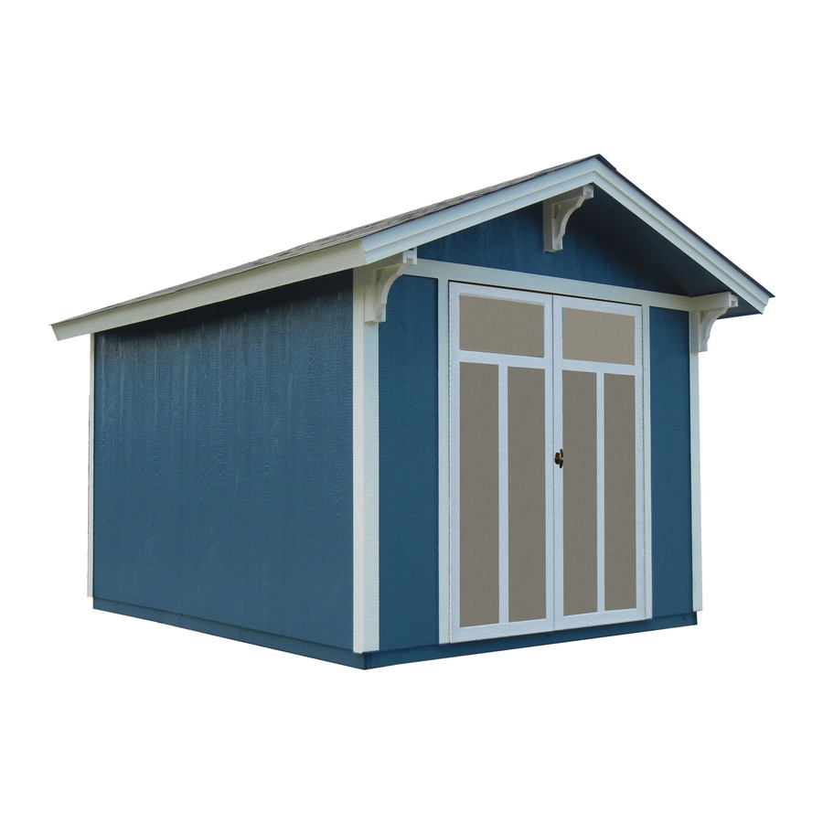
16660 01/13/2016 ASSEMBLY MANUAL A Backyard Products Company ARCHITECTURAL SERIES PRESTWICK 8' x 10' (244 x 304,8 cm) ACTUAL FLOOR SIZE IS: 96" x 120" (243,8 x 304,8 cm) KEEP THIS MANUAL FOR FUTURE REFERENCE I M PO RTA N T ! READ INSTRUCTIONS THOROUGHLY PRIOR TO BEGINNING ASSEMBLY. - Page 4 TOOLS Required Optional Phillips Tool Belt/ Utility Knife Screwdriver Nail Pouch Shingle Blades Tin Snips Drill / Driver (for drip edge) Caulk Gun 5/16" Drill Bit Chalk Line 1/8" Drill Bit ...
-
Page 5: Parts List
PARTS LIST INVENTORY YOUR PARTS before you begin. We suggest sorting parts by the category they are listed in. 3/4" 1 x 3 x 5" (2,5 x 7,6 x 12,7 cm) Gauge Block for 3/4" (1,9 cm) measurement (1,9 cm) 2 x 4 x 17-1/2"... - Page 6 WALL PANELS, OVERHANG, SOFFIT & DOORS NOTE: Panel parts are not stamped. 3/8 x 3-1/2 x 5-7/8" (1 x 8,9 x 14,9 cm) 3/8 x 24-3/8 x 48" 3/8 x 24-3/8 x 48" (1 x 61,9 x 121,9 cm) (1 x 61,9 x 121,9 cm) 3/8 x 11-7/8 x 58-1/4"...
-
Page 7: Additional Materials
ADDITIONAL MATERIALS FOUNDATION OR FLOOR MATERIALS • This shed does not include any floor or leveling materials. Use our optional floor kit with building instructions and nails included. • See the FLOOR LEVELING section on page 8 for recommended methods and suggested materials to properly level your floor, as this will vary depending on your specific site. - Page 8 CONCRETE FOUNDATION If you choose to install your kit on a concrete slab refer to the diagram below. Treated Sill Plate Caulk between sill plate and concrete. 3-1/2" (8,9 cm) 4" (10,2 cm) Building Size Actual Floor Size 113" (287 cm) 8' x 10' (235 x 304,8 cm) 96"...
-
Page 9: Material Required
BUILD YOUR OWN WOOD FLOOR OPTION (Materials not included.) 93" (236,2 cm) 120" (304,8 cm) 16" (40,6 cm) 16" 96" (40,6 cm) (243,8 cm) MATERIAL REQUIRED 2" x 4" x 10' (5,1 x 10,2 x 304,8 cm) MUST be treated lumber 2"... - Page 10 OPTIONAL WOOD FRAME FLOOR LEVELING OPTIONS There are multiple ways to level your floor frame. Our recommended leveling method is shown below. Leveling materials are not included in this kit. PREFERRED METHOD - 4x4 TREATED RUNNERS (Typical for 8' x 10' Kit) 96"...
- Page 11 LEVEL AND SQUARE FLOOR FRAME Before attaching fl oor decking, it is important to level and square the fl oor frame. A level and square fl oor frame is required to correctly construct your shed. BEGIN See page 8 for the preferred fl oor leveling method. Use level and check the frame is level before applying fl oor panels.
- Page 12 IMPORTANT! I M P O R T A N T ! Check the floor frame is level after installing floor panels. Re-level if needed. • The floor should be used as a stable work surface for wall construction. HINT: • Organize your assembly procedure during the build process to avoid over-handling of the walls.
-
Page 13: Parts Required
RAFTER ASSEMBLY PARTS REQUIRED: 3" (7,6 cm) 2 x 4 x 5-7/8" (5,1 x 10,2 x 14,9 cm) It is very important to assemble your rafters using the following method for an even and fl at roof. You will build a rafter jig using the fl oor and three PVA parts as shown. ¸... - Page 14 RAFTER ASSEMBLY PARTS REQUIRED: x 10 x 108 2" (5,1 cm) 1-5/8" (4,1 cm) OSB OR WOOD GRAIN 6 x 24" (15,2 x 61 cm) 2 x 4 x 59-7/8" (5,1 x 10,2 x 152,1 cm) YOU WILL BUILD 5 RAFTERS - ONE OF WHICH WILL HAVE ONLY 1 GUSSET ¸...
- Page 15 BACK WALL FRAME PARTS REQUIRED: 3" (7,6 cm) 2 x 4 x 73-1/2" (5,1 x 10,2 x 186,7 cm) 3" (7,6 cm) 2 x 4 x 89" (5,1 x 10,2 x 226,1 cm) BEGIN Orient parts on fl oor as shown (Fig. A). Measure and mark. HINT: Fasten to THA with one 3"...
- Page 16 BACK WALL PANELS PARTS REQUIRED: 2" (5,1 cm) 1-1/2" (3,8 cm) Temporary Support 3/8 x 48 x 76" 2 x 4 x 48" (5,1 x 10,2 x 122 cm) (1 x 121,9 x 193 cm) BEGIN Carefully flip the back wall frame over. Place SP on flat under THA for temporary support as shown.
- Page 17 BACK WALL PANELS PARTS REQUIRED: 2" (5,1 cm) 1-1/2" (3,8 cm) Temporary Support 3/8 x 48 x 76" 2 x 4 x 48" (5,1 x 10,2 x 122 cm) (1 x 121,9 x 193 cm) Place panel on frame as shown with primed side facing up and fl ush to installed panel. Use SP to support frame and panel while nailing.
- Page 18 EAVE SIDE WALL FRAMING PARTS REQUIRED: 3" (7,6 cm) 2 x 4 x 48" (5,1 x 10,2 x 122 cm) 2 x 4 x 72" (5,1 x 10,2 x 182,9 cm) IMPORTANT! YOU WILL BUILD IDENTICAL EAVE SIDE WALLS. BEGIN Orient parts on edge on fl oor.
-
Page 19: Gauge Block
EAVE SIDE WALL PANELS PARTS REQUIRED: 2" (5,1 cm) 3/4" GAUGE BLOCK 3/8 x 48 x 76" (1 x 121,9 x 193 cm) Ensure your wall frame is square by installing one panel and squaring frame. BEGIN Place a 48 x 76" panel onto wall frame with primed side up as shown. Use the GAA gauge block to mark the 3/4"... - Page 20 EAVE SIDE WALL PANELS PARTS REQUIRED: 2" (5,1 cm) 3/8 x 23-7/8 x 76" 3/8 x 48 x 76" (1 x 60,6 x 193 cm) (1 x 121,9 x 193 cm) Place 23-7/8" x 76" panel on frame as shown with primed side facing up fl ush with fi rst panel.
- Page 21 FRONT WALL FRAME PARTS REQUIRED: 3" (7,6 cm) 2 x 4 x 56" (5,1 x 10,2 x 142,2 cm) 2 x 4 x 73-1/2" (5,1 x 10,2 x 186,7 cm) 2 x 4 x 89" (5,1 x 10,2 x 226,1 cm) BEGIN Orient parts on fl oor as shown.
- Page 22 FRONT WALL PANELS PARTS REQUIRED: 2" (5,1 cm) Temporary Support LEFT 2 x 4 x 59-7/8" (5,1 x 10,2 x 152,1 cm) 3/8 x 48 x 76" (1 x 121,9 x 193 cm) BEGIN Measure and mark center of top plate (36-3/4"). Center LEFT panel flush to top of frame with primed side facing up.
- Page 23 FRONT WALL PANELS PARTS REQUIRED: 3" (7,6 cm) 2" (5,1 cm) RIGHT Temporary Brace 1-1/4 x 2-1/2 x 69" (3,2 x 6,3 x 175,3 cm) 3/8 x 48 x 76" (1 x 121,9 x 193 cm) Place RIGHT panel on frame with primed side facing up, fl ush to left panel and fl ush along top. Use QHA to support the panel while nailing.
- Page 24 RIGHT EAVE WALL INSTALLATION PARTS REQUIRED 3" (7,6 cm) Temporary Brace 3" (7,6 cm) 1-1/4 x 2-1/2 x 69" (3,2 x 6,3 x 175,3 cm) 2" (5,1 cm) BEGIN Stand right eave wall on fl oor. Center right eave wall assembly on the 120"...
- Page 25 GABLE END WALL INSTALLATION PARTS REQUIRED: 3" (7,6 cm) 1-1/2" (3,8 cm) 2" (5,1 cm) 3" (7,6 cm) 2" (5,1 cm) 2" (3,8 cm) BEGIN Flush Flush Screw Stand wall on fl oor. STEP FIRST SCREW Fig. A It is important to secure the gable end wall 2"...
- Page 26 LEFT EAVE WALL INSTALLATION PARTS REQUIRED: 3" (7,6 cm) 2" (5,1 cm) 2" (5,1 cm) 1-1/2" (3,8 cm) BEGIN Stand eave wall on floor. Center left eave wall on the 120" (304,8 cm) floor Panel dimension. Flush Secure top of wall using one 2" screw into top plate (Fig A).
- Page 27 LEFT EAVE WALL INSTALLATION PARTS REQUIRED: 3" (7,6 cm) 2" (5,1 cm) Nail lower edge of panels to fl oor frame using 2" nails 6" apart. Angle nail to hit fl oor frame (Fig. D). Secure eave wall bottom plates to fl oor using 3" nails (Fig. D). 6"...
- Page 28 FRONT GABLE WALL INSTALLATION PARTS REQUIRED: 3" (7,6 cm) 2" (5,1 cm) 2" (5,1 cm) 3" (7,6 cm) 1-1/2" (3,8 cm) BEGIN Stand front gable wall on floor. It is important to secure the front wall in the following order: Set gable wall on floor and secure using one 2"...
- Page 29 FRONT GABLE WALL INSTALLATION PARTS REQUIRED: Nail lower edge of panels to fl oor using 2" nails 6" apart. Angle nail to hit fl oor frame (Fig. C). 2" (5,1 cm) Nails 6" (15,2 cm) Angle nail to hit fl oor Fig.
- Page 30 BACK WALL GABLE PANELS PARTS REQUIRED: 1-1/2" (3,8 cm) 2 x 4 x 17-1/2" (2,5 x 10,2 x 44,5 cm) LEFT RIGHT Temporary Support 2 x 4 x 48" (5,1 x 10,2 x 122 cm) 3/8 x 24-3/8 x 48" 3/8 x 24-3/8 x 48"...
- Page 31 FRONT WALL GABLE PANELS PARTS REQUIRED: 1-1/2" (3,8 cm) 2 x 4 x 21" (2,5 x 10,2 x 53,3 cm) LEFT RIGHT Temporary Support 2 x 4 x 48" (5,1 x 10,2 x 122 cm) 3/8 x 24-3/8 x 48" 3/8 x 24-3/8 x 48"...
- Page 32 FRONT GABLE LADDER PARTS REQUIRED: 3" (7,6 cm) 2 x 4 x 8-7/8" (5,1 x 10,2 x 22,5 cm) 2 x 4 x 61-7/8" (5,1 x 10,2 x 157,2 cm) BEGIN Orient parts as shown (Fig. A). You will build TWO ladder assemblies (Fig. B). Arrange, measure and mark locations of four RCO as shown place QHA on top.
- Page 33 FRONT GABLE UNIT PARTS REQUIRED: 3" (7,6 cm) 1-5/8" (4,1 cm) 2 x 4 x 5-7/8" Front Gable Assembly x1 Ladder Unit (5,1 x 10,2 x 14,9 cm) BEGIN Orient gable and ladder assemblies as shown (Fig. A). Ensure gable panels are fl ush at peak of ladder unit and fl ush along top edge of ladder assembly.
- Page 34 FRONT GABLE UNIT PARTS REQUIRED: 3" (7,6 cm) 2" (5,1 cm) Front Gable Unit BEGIN Attach front gable unit on front wall top plate. It is important to secure the gable unit in the following order: Measure 2-1/8" down from top plate and mark at each side as shown. Set gable unit on top plate. Secure with one 2"...
- Page 35 BACK GABLE PANELS PARTS REQUIRED: 3" (7,6 cm) 2" (5,1 cm) Back Gable Assembly BEGIN Attach back gable assembly on front wall top plate. It is important to secure the gable assembly in the following order: Measure 2-1/8" down from top plate and mark at each side as shown. Set gable assembly on top plate. Secure with one 2"...
- Page 36 RAFTERS PARTS REQUIRED: 3" (7,6 cm) Pre-assembled Rafter Pre-assembled Rafter with 2 gussets with 1 gusset BEGIN Mark top plates and wall panels to measurements shown. Place two-gusset rafters to marks on top plate, aligned over studs and tight to side wall on both sides of shed (Fig. A, Fig. B). Secure rafters with two 3"...
- Page 37 RAFTERS PARTS REQUIRED: 3" (7,6 cm) 2 x 4 x 5-7/8" (5,1 x 10,2 x 14,9 cm) 2 x 3 x 22-1/2" (5,1 x 7,6 x 57,1 cm) BEGIN Place eave nailer LV between two center rafters. Keep LV fl ush to bottom of outside edge of rafter (Fig. A, Fig. B). Pre-drill a 1/8"...
- Page 38 FRONT GABLE SOFFIT PANELS PARTS REQUIRED: 2" (5,1 cm) 3/8 x 11-7/8 x 58-1/4" (1 x 30,2 x 148 cm) Ensure soffi t boards are fl ush at seam and fl ush at overhang end (Fig. A). BEGIN Position right 58-1/4" soffi t board Primed Side Down fl ush to front wall and gable panel seam (Fig A).
- Page 39 EAVE SIDE SOFFIT PANELS PARTS REQUIRED: 2" (5,1 cm) 3/8 x 5-7/8 x 47-7/8" (1 x 12,1 x 121,6 cm) 3/8 x 5-7/8 x 73-5/8" (1 x 14,9 x 187,6 cm) Ensure soffi t boards are fl ush at rafter ends (Fig. B) and fl ush at seams. BEGIN Position soffi t boards primed side down fl ush to gable soffi t and rafter ends (Fig A).
- Page 40 CORNER TRIM PARTS REQUIRED: 2" (5,1 cm) 3/8 x 2-13/16 x 73-7/8" (1 x 7,1 x 187,6 cm) ¸ BEGIN Place one 2-13/16" x 73-7/8" trim board fl ush under gable panel and fl ush with eave wall panel (Fig. A). Secure using one 2"...
- Page 41 CORBELS PARTS REQUIRED: 2" (5,1 cm) 1 x 3 x 9-1/2" (2,5 x 7,6 x 24,17 cm) 1 x 3 x 11-7/8" (2,5 x 7,6 x 30,2 cm) 1 x 4 x 11-7/8" (2,5 x 10,2 x 30,2 cm) x3 PKA x3 PRO 2 x 2 x 12"...
-
Page 42: Inside View
CORBELS PARTS REQUIRED: 3" (7,6 cm) LEFT RIGHT CORBEL CORBEL BEGIN Locate left corbel centered on the front corner trim and tight against the bottom of soffit as shown (Fig. A). Fasten from inside using three 3" screws as shown (Fig. B). 4"... - Page 43 CORBELS PARTS REQUIRED: 3" (7,6 cm) CENTER CORBEL BEGIN Locate center corbel centered on the seam of the gable panels and tight against the bottom of soffi t (Fig. A). Fasten from inside using three 3" screws as shown measuring from the top of the gable connector (Fig.
- Page 44 ROOF PANELS PARTS REQUIRED: 2" (5,1 cm) 3/4" GAUGE BLOCK 7/16 x 48 x 96" 7/16 x 48 x 36" (1,1 x 121,9 x 243,8 cm) (1,1 x 121,9 x 91,4 cm) Roof panels may cause serious injury until securely fastened. BEGIN Attach the 48"...
- Page 45 ROOF PANELS PARTS REQUIRED: x148 2" (5,1 cm) 7/16 x 11-7/8 x 48" 7/16 x 11-7/8 x 84" (1,1 x 30,2 x 121,9 cm) (1,1 x 30,2 x 213,4 cm) Keep spacing between the center of the rafters and gable panels at the upper edge of the panels. Secure panels with one 2"...
- Page 46 ROOF PANELS PARTS REQUIRED: 7/16 x 11-7/8 x 48" 7/16 x 11-7/8 x 84" (1,1 x 30,2 x 121,9 cm) (1,1 x 30,2 x 213,4 cm) Attach the 11-7/8" x 84" roof panel fl ush to the lower installed panels, 3/4" measurement at rafter center (Fig.
- Page 47 FRONT GABLE FASCIA PARTS REQUIRED: 2" (5,1 cm) 3/8 x 4-3/4 x 61" (1 x 12,1 x 154,9 cm) 3/8 x 4-3/4 x 61" (1 x 12,1 x 154,9 cm) BEGIN Position fascia with primed side out and fl ush to peak and roof panels as shown (Fig. A, Fig B). Secure using 2"...
- Page 48 GABLE TRIM PARTS REQUIRED: 2" (5,1 cm) 3/8 x 2-1/2 x 61" (1 x 6,4 x 154,9 cm) 3/8 x 2-1/2 x 61" (1 x 6,4 x 154,9 cm) BEGIN Position trim with primed side out and fl ush to peak and roof panels as shown (Fig. A, Fig B). Secure using 2"...
- Page 49 BACK GABLE FASCIA PARTS REQUIRED: 2" (5,1 cm) 1" (2,5 cm) 3/8 x 4-3/4 x 61" (1 x 12,1 x 154,9 cm) 3/8 x 3-1/2 x 5-7/8" 3/8 x 4-3/4 x 61" (1 x 12,1 x 154,9 cm) (1 x 8,9 x 14,9 cm) BEGIN Position 3-1/2"...
- Page 50 EAVE SIDE FASCIA PARTS REQUIRED: 2" (5,1 cm) 3/8 x 4-3/4 x 61-1/2" (1 x 12,1 x 156,2 cm) 3/8 x 4-3/4 x 72" (1 x 12,1 x 182,9 cm) BEGIN Position fascia boards with primed side out, fl ush with roof panels and gable fascia as shown (Fig. A). Install 72"...
- Page 51 OVER DOOR TRIM PARTS REQUIRED: 2" (5,1 cm) 3/4" (1,9 cm) 19/32 x 2-1/2 x 63" (1,5 x 6,4 x 160 cm) BEGIN Center WR tight up against front gable panels. Attach using 2" fi nish nails along bottom edge as shown. Ensure nails are into wall framing.
- Page 52 DOORS PARTS REQUIRED: 3" (7,6 cm) 1-1/4 x 2-1/2 x 69" (3,2 x 7,6 x 175,3 cm) 1-1/4" (3,2 cm) TEMPORARY SUPPORT HINT: Look for 3/8" SPACER attached to doors. x1 GAA 1 x 3 x 5" (2,5 x 7,6 x 12,7 cm) Left Door Right Door BEGIN...
- Page 53 DOORS PARTS REQUIRED: 3" (7,6 cm) 1-1/4 x 2-1/2 x 69" (3,2 x 7,6 x 175,3 cm) TEMPORARY SUPPORT Attach temporary support OO as a ledger board fl ush under wall panels for doors to rest on, using two 3" screws (Fig. A) . Flush under panel Fig.
- Page 54 DOORS PARTS REQUIRED: 3/4" (1,9 cm) 19/32 x 2-1/2 x 23" (1,5 x 6,3 x 58,4 cm) 19/32 x 2-1/2 x 55-1/8" (1,5 x 6,3 x 140 cm) BEGIN Reinforce the door trim using 3/4" screws through door panel into trim (Fig. A). Locate screws as shown (Fig.
- Page 55 DOOR WEATHERSTRIP PARTS REQUIRED: 2" (5 cm) 1-1/4 x 2-1/2 x 69" (3,2 x 7,6 x 175,3 cm) BEGIN With left door closed, center a weatherstrip OO vertically on the left door in the door opening (Fig. A). OO will offset the left door 1" OUT past the door trim 1" (Fig. B). Secure OO using seven 2"...
- Page 56 THRESHOLD / DOOR HARDWARE PARTS REQUIRED: 3/4" (1,9 cm) Bagged separately / special coating 1/2" (13 mm) Drill Bit 1/4" (6 mm) Drill Bit 1-1/2" (3,8 cm) 56" (142,2 cm) Metal Threshold BEGIN Measure and mark location of hole on outside of right door as shown (Fig. A). Pre-drill hole with 1/4" drill. Re-drill hole with 1/2"...
- Page 57 D-BOLTS PARTS REQUIRED: 1" (2,5 cm) 5/16" (0,8 cm) Drill Bit BEGIN Place bolt onto OO in open position with bolt end 3/8" down from frame. Bolt is open when loop is contacting base (Fig A) . Mark and pre-drill holes for screws. Install bolt with screws supplied and drill 5/16"...
- Page 58 VENTS PARTS REQUIRED: 1/2" (1,2 cm) 8 x 16" (20,3 x 35,6 cm) ¸ BEGIN Locate and mark openings for two vents in side walls on opposite sides of shed; (1) at top of wall panel and (1) at bottom of the other wall. Cut out marked openings.
- Page 59 PAINT & CAULK - NOT INCLUDED - • Use acrylic latex caulk that is paintable. Caulk at all horizontal and vertical seams, between the trim and walls, and all around the door trim. • Use a high quality exterior acrylic latex paint. When painting your building, there are a few key areas that can be easily overlooked that must be painted: •...
- Page 60 SHINGLES - NOT INCLUDED - • Follow directions provided by manufacturer and these instructions. Familiarize yourself with a 3-Tab Shingle. Notch Notch SHINGLE NAIL PATTERN 1/2" 1" Sealing Strip 1" (1,3 cm) (2,5 cm) (2,5 cm) Half A Rain Slot Full Rain Slot NAILS NEVER DRIVE FASTENERS INTO OR ABOVE SEALING STRIPS.
- Page 61 SHINGLES continued... Beginning at front of shed, install first row of shingles with notch at 1" past roof edge or flush with drip edge. Roof Deck FRONT OF BACK OF SHED SHED 1" (2,5 cm) Flush with starter row. Notch - or - Drip Edge Flush with starter row.
- Page 62 SHINGLES continued... Continue installing rows of shingles to the peak. At the peak make sure there is a maximum of 5" or less to the rain slot, as shown below. If shingles overlap at ridge cut to peak with a utility knife. 5"...
- Page 63 SHINGLES - RIDGE CAP • You will finish off the top of the roof with a ridge cap made from shingles. BEGIN Cut shingles into THREE pieces. Hint: Use cut-off pieces first. 2" 2" (5,1 cm) (5,1 cm) 2" 2" 2"...
- Page 64 SHINGLES - RIDGE CAP continued... Continue installing ridge cap to back of roof. Make sure there is 4" between the shingle-color and edge of shingles. Trim cap off fl ush to shingles When you have 4" minimum of shingle color cut one piece to cap your roof. Install fl ush to shingles.
- Page 65 All Oriented Strand Board (OSB) is warranted for 2 years Siding and Trim is warranted for: 10 years: Value Series / Solar Shed 12 years: Classic Series / Architectural Series 15 years: Big Buildings Solar Shed windows are warranted for 1 year.
Need help?
Do you have a question about the ARCHITECTURAL SERIES and is the answer not in the manual?
Questions and answers