Download Print this page

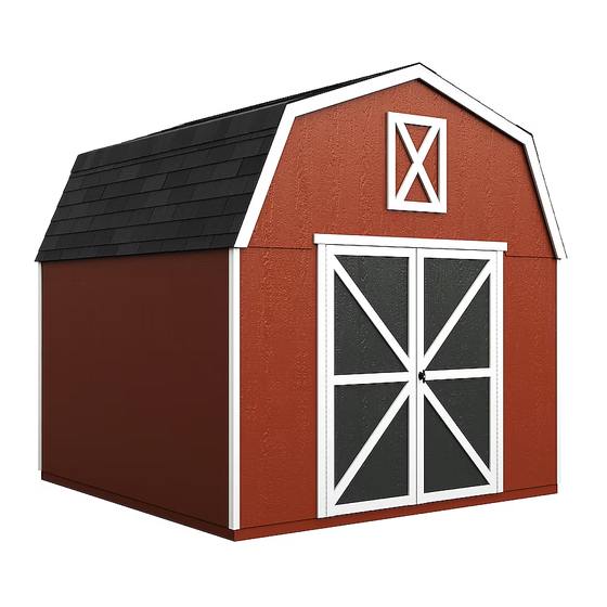
Heartland VALUE Series Assembly Manual

10' x 10' (304,8 x 304,8 cm)
Hide thumbs Also See for VALUE Series:

Advertisement

Quick Links

For questions on assembly or for general inquiries, you may contact us in the following ways:
Call a Recruiter Today! 734-365-7000
Flexible schedule
*based on number of completed installations
Call Us First!
DO NOT RETURN TO STORE.
Call customer service: 1-877-743-3400
AVOID THE WAIT!
visit us online at
help.backyardproducts.com
Submit a help request
Answers to frequently asked questions
Live chat with an agent
Did you enjoy building your shed?
JOIN OUR TEAM
AND MAKE UP TO $1,500/WEEK*
No selling,
just building
Bonus incentives
available
16165

Advertisement

loading

Summary of Contents for Heartland VALUE Series

  • Page 1 16165 Call Us First! DO NOT RETURN TO STORE. For questions on assembly or for general inquiries, you may contact us in the following ways: Call customer service: 1-877-743-3400 AVOID THE WAIT! visit us online at help.backyardproducts.com Submit a help request Answers to frequently asked questions Live chat with an agent Did you enjoy building your shed?
  • Page 2 (This page intentionally left blank.)
  • Page 3: Assembly Manual

    16165 10/28/2021 ASSEMBLY MANUAL VALUE SERIES STILLWATER 10' x 10' (304,8 x 304,8 cm) BUILDING SIZE ACTUAL FLOOR SIZE 10' x 10' (304,8 x 304,8 cm) 10' x 10' (304,8 x 304,8 cm) BASE MODEL 10' x 14' (304,8 x 426,7 cm)
  • Page 4 TOOLS Required Optional ❑ Phillips ❑ Tool Belt/ ❑ Utility Knife Screwdriver Nail Pouch ❑ Shingle Blades ❑ Drill / Driver ❑ Tin Snips ❑ 3/8" Drill Bit ❑ Caulk Gun (for drip edge) ❑ #2 Philips Drive Bit ❑ Chalk Line ❑...
  • Page 5 PARTS IDENTIFICATION AND SIZES WOOD SIZE CONVERSION CHART Double letter part identification is stamped on some parts. Nominal Board Size Actual Size 2 x 4 ....1-1/2" x 3-1/2" (3,8 x 8,9 cm) 1 x 4 ....3/4" x 3-1/2" (1,9 x 8,9 cm) •...
  • Page 6 PANEL & DOORS PARTS LIST NOTE: Panel parts are not stamped with part identification. SQUARE SQUARE SQUARE EDGE EDGE EDGE LIP EDGE Left Right 3/8" x 48" x 48" 3/8" x 48" x 48" 3/8" x 23-7/8" x 52-1/4" 3/8" x 23-7/8" x 50-13/16" 3/8"...
  • Page 7 NAIL BOXES (Shown Actual Size) BOXES 3" (7,6 cm) 2" (5,1 cm) BOXES FASTENER/HARDWARE BAG (Shown Actual Size) x115 1-1/2" (3,8 cm) x185 2" (5,1 cm) 3" (7,6 cm) 2" (5,1 cm) 1-1/4" (3,2 cm) NOTE: If you are using a nail gun, nails x100 3/4"...
  • Page 8 GAMBREL EXTENDER KIT PARTS LIST Inventory your parts before you begin. We suggest sorting parts by the category they are listed in. WOOD SIZE CONVERSION CHART Part identification is stamped on some parts. Nominal Board Size Actual Size 2 x 4 ....1-1/2" x 3-1/2" (3,8 x 8,9 cm) 1 x 4 ....3/4"...
  • Page 9 ADDITIONAL MATERIALS FOUNDATION OR FLOOR MATERIALS • If your shed came with a separate floor kit, then please use the instructions supplied with that kit to assemble your floor. • See the FLOOR LEVELING section on page 11 for recommended methods and suggested materials to properly level your floor, as this will vary depending on your specific site.
  • Page 10: Optional Materials

    ADDITIONAL MATERIALS COMPLETING YOUR SHED You will need these additional materials: 10x10' 10x14' 10x10' 10x14' Paint for trim/Quart 3-TAB SHINGLES (Bundles)..Use 100% acrylic latex exterior paint. PAINT FOR SIDING (Gallons)..Caulk Tubes ... Use 100% acrylic latex exterior paint. Use acrylic paintable (2) coats recommended.
  • Page 11 CONCRETE FOUNDATION If you choose to install your kit on a concrete slab refer to the diagram below. Attach the sill plates on the foundaton as shown, and continue on to page 17. Treated Sill Plate Caulk between sill plate and concrete.
  • Page 12 BUILD YOUR OWN WOOD FLOOR OPTION (Materials not included.) 117" 120" (297,2 cm) (304,8 cm) MUST be treated lumber 10' x 10' 120" (304,8 cm) 16" MATERIAL REQUIRED (40,6 cm) 2 x 4 x 10' (5,1 x 10,2 x 304,8 cm) 2 x 4 x 117"...
  • Page 13 OPTIONAL WOOD FRAME FLOOR LEVELING OPTIONS There are multiple ways to level your floor frame. Our recommended leveling method is shown below. Leveling materials are not included in this kit. PREFERRED METHOD - 4x4 TREATED RUNNERS (Typical for 10' x 10' Kit) Runners are generally 12"...
  • Page 14 10' x 10' FLOOR FRAME PARTS REQUIRED: 3" (7,6 cm) 2 x 4 x 117" (5,1 x 10,2 x 297,2 cm) Look for TREATED 2 x 4 x 120" (5,1 x 10,2 x 304,8 cm) Stamp BEGIN Arrange parts as shown on flat surface. Measure and mark. HINT: For easier nailing Secure with (2) 3"...
  • Page 15 10' x 14' FLOOR FRAME PARTS REQUIRED: 3" (7,6 cm) 2 x 4 x 117" (5,1 x 10,2 x 297,2 cm) Look for TREATED 2 x 4 x 168" (5,1 x 10,2 x 426,7 cm) Stamp BEGIN Arrange parts as shown on flat surface. Measure and mark. HINT: For easier nailing Secure with (2) 3"...
  • Page 16 LEVELING & SQUARING THE FLOOR FRAME (Not Included) LEVEL AND SQUARE FLOOR FRAME Before attaching floor decking, it is important to level and square the floor frame. A level and square floor frame is required to correctly construct your shed. See page 10 for the preferred foor leveling method.
  • Page 17 10' x 10' FLOOR PANELS PARTS REQUIRED: x212 Precut panels to these sizes: 2" (5,1 cm) 5/8 x 23-7/8 x 23-7/8" (1,6 x 60,6 x 60,6 cm) 5/8 x 48 x 96" 5/8 x 23-7/8 x 48" (1,6 x 121,9 x 243,8 cm) (1,6 x 60,6 x 121,9 cm) 3/4"...
  • Page 18 10' x 14' FLOOR PANELS PARTS REQUIRED: Precut panels to these sizes: x256 2" (5,1 cm) 5/8 x 47-7/8 x 47-7/8" (1,6 x 121,6 x 121,6 cm) 5/8 x 48 x 96" 5/8 x 48 x 72" 5/8 x 23-7/8 x 48" (1,6 x 121,9 x 243,8 cm) (1,6 x 121,9 x 182,9 cm) (1,6 x 60,6 x 121,9 cm)
  • Page 19 IMPORTANT! I M P O R T A N T ! NOTE: 10' x 10' floor shown as an example. Ensure the foor frame is level after installing foor panels. Re-level if needed. • The foor should used as a stable work surface for wall construction. •...
  • Page 20 WALL INDEX 10' x 10' After assembling the walls for your 10' x 10' shed, go to page 28 for wall installation. 10' x 10' Wall 01: Page 20 Wall 02: Page 22 Wall 03: Page 24 (Build 2 eave walls) 10' x 14' After assembling the walls for your 10' x 14' shed, go to page 33 for wall installation.
  • Page 21 WALL PANEL INSTALLATION HINTS & EXAMPLES PARTS REQUIRED: 2" (5,1 cm) 3/4" GAUGE BLOCK 3/8 x 48 x 72" (1 x 121,9 x 182,9 cm ) Ensure your wall is square by installing one panel and squaring frame. Install all wall panels with the primed side facing up. BEGIN 2 Nails Place a 48"...
  • Page 22 GABLE WALL 01 WITH DOOR PARTS REQUIRED: 3" (7,6 cm) x1 DPD 2 x 4 x 27-3/8" (5,1 x 10,2 x 69,5 cm) x2 RR 2 x 4 x 28" (5,1 x 10,2 x 71,1 cm) 2 x 4 x 68" (5,1 x 10,2 x 172,7 cm) 2 x 4 x 92-5/8"...
  • Page 23 GABLE WALL 01 WITH DOOR PARTS REQUIRED: 3" (7,6 cm) SQUARE SQUARE x116 3/8 x 11-7/8 x 72" 3/8 x 15-7/8 x 72" EDGE 3/8 x 11-7/8 x 72" EDGE (1 x 30,2 x 182,9 cm) (1 x 40,3 x 182,9 cm) (1 x 30,2 x 182,9 cm) 2"...
  • Page 24 GABLE WALL 02 PARTS REQUIRED: 3" (7,6 cm) 2 x 4 x 24" (5,1 x 10,2 x 61 cm) 2 x 4 x 68" (5,1 x 10,2 x 172,7 cm) 2 x 4 x 96" (5,1 x 10,2 x 243,8 cm) BEGIN Arrange parts on edge on floor as shown.
  • Page 25 GABLE WALL 02 PARTS REQUIRED: x122 2" (5,1 cm) 48 x 72" 23-7/8" x 72" (121,9 x 182,9 cm ) (60,6 x 182,9 cm ) 3/4" BEGIN HERE Install (1) 48" x 72" panel (1,9 cm) flush to the top plate. Secure panel with 2"...
  • Page 26 10' EAVE WALL 03 PARTS REQUIRED: 3" (7,6 cm) 2 x 4 x 20-3/8" (5,1 x 10,2 x 51,8 cm) 2 x 4 x 68" (5,1 x 10,2 x 172,7 cm) 2 x 4 x 92-5/8" (5,1 x 10,2 x 235,3 cm) Build two identical walls.
  • Page 27 10' EAVE WALL 03 PARTS REQUIRED: x122 2" (5,1 cm) 48 x 72" 23-7/8" x 72" (121,9 x 182,9 cm ) (60,6 x 182,9 cm ) 3-1/2" Install 48" x 72" panel (8,9 cm) 3/4" Flush BEGIN HERE 1-1/2" from the top plate. (1,9 cm) Secure panel with 2"...
  • Page 28 14' EAVE WALL 04 PARTS REQUIRED: 3" (7,6 cm) 2 x 4 x 68" (5,1 x 10,2 x 172,7 cm) 2 x 4 x 68-3/8" (5,1 x 10,2 x 173,7 cm) 2 x 4 x 92-5/8" (5,1 x 10,2 x 235,3 cm) Build two identical walls.
  • Page 29 14' EAVE WALL 04 PARTS REQUIRED: x165 2" (5,1 cm) 23-7/8" x 72" (60,6 x 182,9 cm ) 48 x 72" (121,9 x 182,9 cm ) 3/4" BEGIN HERE (1,9 cm) Install (1) 48" x 72" panel 1-1/2" from the top plate. 6"...
  • Page 30 STANDING YOUR WALLS The following steps show how to stand and secure your walls for a 10' x 10' shed. For a 10' x 14' shed, start on page 33.
  • Page 31 10' GABLE WALL 02 INSTALLATION PARTS REQUIRED: 3" (7,6 cm) Temporary Brace 69" (175,3 cm) Door Stiffener 3" (7,6 cm) 2" (5,1 cm) BEGIN Center 10' wall on the 120" (304,8 cm) floor dimension. 1" (2,5 cm) overlap is to the bottom. Install OO as a temporary brace.
  • Page 32 1st EAVE WALL 03 INSTALLATION PARTS REQUIRED 2" (5,1 cm) 3" (7,6 cm) 2" (5,1 cm) 1-1/2" (3,8 cm) 3" (7,6 cm) Fig. B BEGIN Place 10' eave wall centered on floor. 1" (2,5 cm) overlap is to the bottom. 2"...
  • Page 33 2nd EAVE WALL 03 INSTALLATION PARTS REQUIRED: 2" (5,1 cm) 3" (7,6 cm) 2" (5,1 cm) 3" (7,6 cm) 1-1/2" (3,8 cm) Fig. B BEGIN Remove temporary brace OO from installed 10' gable wall. Place 2nd 10' eave wall centered on floor. 2"...
  • Page 34 10' GABLE WALL 01 INSTALLATION PARTS REQUIRED 2" (5,1 cm) 3" (7,6 cm) 2" (5,1 cm) 1-1/2" (3,8 cm) 3" (7,6 cm) Fig. B BEGIN 2" (5,1 cm) Screw Place 10' gable wall on floor centered between installed' walls. Secure wall with 2" screws into top and bottom plates Flush (Fig.
  • Page 35 10' GABLE WALL 02 INSTALLATION PARTS REQUIRED: 3" (7,6 cm) 69" (175,3 cm) Door Stiffener 3" (7,6 cm) 2" (5,1 cm) BEGIN Center 10' wall on the 120" (304,8 cm) floor dimension. 1" (2,5 cm) overlap is to the bottom. 3"...
  • Page 36 1st EAVE WALL 04 INSTALLATION PARTS REQUIRED 2" (5,1 cm) 3" (7,6 cm) Temporary Brace 1-1/2" (3,8 cm) 2 x 3 x 72" (5,1 x 7,6 x 182,9 cm) 2" (5,1 cm) 3" (7,6 cm) Fig. B BEGIN Place 1st 14' eave wall centered on floor. 1"...
  • Page 37 2nd EAVE WALL 04 INSTALLATION PARTS REQUIRED: 69" (175,3 cm) Door Stiffener Temporary Brace 2" (5,1 cm) 3" (7,6 cm) 1-1/2" (3,8 cm) 2" (5,1 cm) 3" (7,6 cm) BEGIN Remove temporary brace OO from installed 10' wall. Fig. B Place 2nd 14' wall centered on floor.
  • Page 38 10' GABLE WALL 01 INSTALLATION PARTS REQUIRED 2" (5,1 cm) 3" (7,6 cm) 2" (5,1 cm) 1-1/2" (3,8 cm) 3" (7,6 cm) Fig. B BEGIN 2" (5,1 cm) Screw Place 10' gable wall on floor centered between installed' walls. Secure wall with 2" screws into top and bottom plates Flush (Fig.
  • Page 39 OVER DOOR DOUBLER PARTS REQUIRED 3" (7,6 cm) 2 x 3 x 72" (5,1 x 7,6 x 182,9 cm) BEGIN Measure, mark and center doubler OY on top plate, over door. Flush OY to face of wall panels (Fig. A). Secure ends of OY with (2) 3"...
  • Page 40 RAFTERS 10x10' 10x14' PARTS REQUIRED: 6 x 24" (15,2 x 60,9 cm) x1 RL Temporary Support 2 x 4 x 24" (5,1 x 10,2 x 61 cm) Pre-assembled x120 x168 2" (5,1 cm) Build (2) rafter assemblies with(1) gusset (Fig. B). BEGIN Place two rafter-halves on floor and flush base ends (with nub) in the corners of 10' wall.
  • Page 41 RAFTER INSTALLATION 10x10' 10x14' PARTS REQUIRED: Two-Gusset Preassembled One-Gusset Preassembled 3" (7,6 cm) BEGIN Align rafters over the wall studs. Check that you have the measurements shown. Secure middle rafters with (2) 3" screws angled into doubler (Fig. A). Secure (2) end rafters with (2) 3" screws into outside of each end rafter (Fig. B). Secure rafters on opposite side.
  • Page 42 BACK GABLE UNIT PARTS REQUIRED: 1-1/2" (3,8cm) x2 GPP 23-7/8" x 52-1/4" 2 x 4 x 43-3/16" (5,1 x 10,2 x 109,7 cm) (60,6 x 132,7 cm) Install gable panels with the primed side facing up. BEGIN Arrange back gable parts GPP on the flat side, as shown. Measure and mark the center of the 27-3/8"...
  • Page 43 FRONT GABLE HAY LOFT TRIM PARTS REQUIRED: 2" (5,1 cm) 3/4" (19 mm) 19/32" x 2-1/2" x 12-7/8" (1,6 x 7,6 x 32,7 cm) Temporary Brace 69" (175,3 cm) Door Stiffener 19/32" x 2-1/2" X 21-3/4" (1,6 x 7,6 x 55,2 cm) x1 LKA 23-7/8"...
  • Page 44 FRONT GABLE UNIT PARTS REQUIRED: 1-1/2" (3,8cm) 2 x 4 x 41-11/16" (5,1 x 10,2 x 105,9 cm) Install gable panels with the primed side facing up. BEGIN Arrange front gable parts FIB on the flat side, as shown. Measure and mark the center of the middle gable panel. Secure with 1-1/2" nails spaced 6" apart along edge. 1-3/4"...
  • Page 45 BACK GABLE UNIT INSTALLATION PARTS REQUIRED: 3" (7,6 cm) 2" (5,1 cm) Pre - assembled BEGIN Measure 1-1/2" (3,8 cm) down from top plate and mark at each side as shown. Set back gable unit centered on back wall top plate. Fasten with (1) 2" nail on each side. BE SURE GABLE IS CENTERED ON WALL BEFORE NAILING.
  • Page 46 FRONT GABLE UNIT INSTALLATION PARTS REQUIRED: 3" (7,6 cm) 2" (5,1 cm) Pre - assembled BEGIN Measure 3" (7,6 cm) down from top plate doubler and mark at each side as shown. Set front gable unit centered on front wall doubler. Fasten with (1) 2" nail on each side. BE SURE GABLE IS CENTERED ON WALL BEFORE NAILING.
  • Page 47 10' x 10' ROOF PANELS PARTS REQUIRED: 2" (5,1 cm) 3/4" GAUGE BLOCK 48 x 96" (121,9 x 243,8 cm) Roof panels may cause serious injury until securely fastened. Note: Install all roof panels with the rough side up (painted grid lines). BEGIN Flush at peak...
  • Page 48 10' x 10' ROOF PANELS PARTS REQUIRED: 2" (5,1 cm) 7/16 x 23-7/8 x 48" (1,1 x 60,6 x 121,9 cm) Flush at peak Fig. B Install (1) 23-7/8" x 48" roof panel flush to the 1/2" (1,2 cm) installed panel and flush at peak (Fig. B). Fig.
  • Page 49 10' x 10' ROOF PANELS PARTS REQUIRED: 2" (5,1 cm) 23-7/8" x 96" 23-7/8" x 23-7/8" (60,6 x 243,8 cm) (60,6 x 60,6 cm) 3/4" GAUGE BLOCK 15-7/8" x 96" 15-7/8" x 23-7/8" (40,3 x 60,6 cm) (40,3 cm x 243,8 cm) Next, install 23-7/8"...
  • Page 50 10' x 10' ROOF PANELS PARTS REQUIRED: x160 2" (5,1 cm) Secure all roof panels with 2" nails spaced 6" apart and 12" apart inside of the upper panels. 6" (15,2 cm) Repeat all steps to install roof panels on the opposite side. FINISH Your roof panels are now installed.
  • Page 51 10' x 14' ROOF PANELS PARTS REQUIRED: 2" (5,1 cm) 3/4" GAUGE BLOCK 48 x 96" (121,9 x 243,8 cm) Roof panels may cause serious injury until securely fastened. Note: Install all roof panels with the rough side up (painted grid lines). BEGIN Flush at peak...
  • Page 52 10' x 14' ROOF PANELS PARTS REQUIRED: 2" (5,1 cm) 47-7/8 x 48" 23-7/8 x 48" (121,6 x 121,9 cm) (121,6 x 121,9 cm) Flush at 1/2" peak Install 47-7/8" x 48" roof panel (1,2 cm) Fig. B flush to the installed panel and flush at the peak (Fig.
  • Page 53 10' x 14' ROOF PANELS PARTS REQUIRED: 2" (5,1 cm) 23-7/8" x 48" 23-7/8" x 96" 23-7/8" x 23-7/8" (60,6 x 121,9 cm) (60,6 x 243,8 cm) (60,6 x 60,6 cm) 3/4" GAUGE BLOCK (15-7/8" x 96" 15-7/8" x 23-7/8" 15-7/8"...
  • Page 54 10' x 14' ROOF PANELS PARTS REQUIRED: x240 2" (5,1 cm) Secure all roof panels with 2" nails spaced 6" apart and 12" apart inside panels. 6" (15,2 cm) Repeat all steps to install roof panels on the opposite side. FINISH Your roof panels are now installed.
  • Page 55 GABLE TRIM PARTS REQUIRED: 2" (5,1 cm) 19/32" x 3-1/2 x 40-3/16" (1,5 x 8,9 x 102,1 cm) 19/32" x 3-1/2 x 48-3/8" (1,5 x 8,9 x 122,9 cm) 19/32" x 3-1/2 x 48-3/8" (1,5 x 8,9 x 122,9 cm) BEGIN Install upper gable trim BBL and BBR flush to top of roof panels and flush at peak.
  • Page 56 CORNER TRIM PARTS REQUIRED: 2" (5,1 cm) 3/8" x 1-3/4" x 71-3/16" (1 x 4,5 x 180,8 cm) BEGIN Install gable end 71-3/16" corner trim under gable panel, (Fig. A) and flush to eave wall panel (Fig. B). Secure with 2" finishing nails spaced evenly. Install eave side 71-3/16"...
  • Page 57 10x10' 10x14' COLLAR TIE INSTALLATION PARTS REQUIRED: 1 x 3 x 96" (2,5 x 7,6 x 243,9 cm) 3" (7,6 cm) BEGIN Install collar tie to the rafter with (3) 3" nails at each end Fig. A (Fig. A). Flush to roof Starting at the wall with the door, install collar tie BE panel 3"...
  • Page 58 DOORS PARTS REQUIRED: 3" (7,6 cm) 1-1/4" (3,2 cm) 1 x 3 x 5" (2,5 x 7,6 x 12,7 cm) 69" (175,3 cm) Door Stiffener Left Door Right Door BEGIN Place doors on flat surface. 3/8" offset is to top. Look for red (right) and green (left) on hinge board.
  • Page 59 DOORS PARTS REQUIRED: 3" (7,6 cm) TEMPORARY SUPPORT 69" (175,3 cm) Door Stiffener Install OO flush under panels. Secure to floor frame with (2) 3" screws (Fig. A). Mark center of door opening. IMPORTANT NOTE: You may need to lower and level OO so that doors will fit under gable panels.
  • Page 60 DOORS PARTS REQUIRED: 2" (5,1 cm) 3/4" (1,9 cm) 19/32" x 2-1/2" x 72" (1,5 x 7,6 x 182,9 cm) 19/32" x 2-1/2" x 41-3/4" (1,5 x 6,3 x 106 cm) 3/4" (1,9 cm) x11 19/32" x 2-1/2" x 41-3/4" (1,5 x 6,3 x 106 cm) Bagged seperately / special coating 64"...
  • Page 61 DOOR STIFFENERS PARTS REQUIRED: 2" (5,1 cm) 69" (175,3 cm) Door Stiffener BEGIN Center OO vertically on the left door in the doorway (Fig. A) overlapping 1" (2,5 cm) along the edge of door (Fig. B). Secure with (7) 2" screws through outside trim into OO. Center OO vertically on the right door in the door opening offset 1"...
  • Page 62: Door Hardware

    DOOR HARDWARE PARTS REQUIRED: 5/16" (7,9 mm) Drill Bit 3/4" (1,9 cm) BEGIN Place bolt on OO in open position with bolt end 3/8" (9,5 mm) down from frame. Bolt is open when loop is contacting base (Fig A). Mark and pre-drill holes for screws. Install bolt with screws supplied. Drill 5/16"...
  • Page 63 DOOR HARDWARE PARTS REQUIRED: 1-1/2" (3,8 cm) 1/2" (12 cm) Drill Bit 1/4" (0,6 cm) Drill Bit Measure and mark location of hole on outside of right door as shown (Fig. A). Pre-drill hole with 1/4" drill. Re-drill hole with 1/2" drill. Keep drilled hole square to trim to avoid breaking edge of door stiffener.
  • Page 64 VENTS (Not included in base model.) • Follow directions provided by manufacturer and these instructions. 1/2" (13 mm) 16" x 8" BEGIN Locate and mark for two vents in side walls as shown; (1) at top and (1) at bottom. Cut out marked openings.
  • Page 65 PAINT & CAULK - NOT INCLUDED - • Use acrylic latex caulk that is paintable. Caulk at all horizontal and vertical seams, between the trim and walls, and all around the door trim. • Use a high quality exterior acrylic latex paint. When painting your building, there are a few key areas that can be easily overlooked that must be painted: •...
  • Page 66 SHINGLES - NOT INCLUDED - • Follow directions provided by manufacturer and these instructions. Familiarize yourself with a 3-Tab Shingle. Notch Notch SHINGLE NAIL PATTERN 1/2" 1" Sealing Strip 1" (1,3 cm) (2,5 cm) (2,5 cm) Half A Rain Slot Full Rain Slot NAILS NEVER DRIVE FASTENERS INTO OR ABOVE SEALING STRIPS.
  • Page 67 SHINGLES continued... Beginning at front of shed, install first row of shingles with notch at 1" past roof edge or flush with drip edge. Roof Deck FRONT OF BACK OF SHED SHED 1" (2,5 cm) Flush with starter row. Notch - or - Drip Edge Flush with starter row.
  • Page 68 SHINGLES continued... Continue installing rows of shingles to the peak. At the peak make sure there is a maximum of 5" or less to the rain slot, as shown below. If shingles overlap at ridge cut to peak with a utility knife. 5"...
  • Page 69 SHINGLES - RIDGE CAP • You will finish off the top of the roof with a ridge cap made from shingles. BEGIN Cut shingles in THREE pieces. Hint: Use cut-off pieces first. 2" 2" (5,1 cm) (5,1 cm) 2" 2" 2"...
  • Page 70 SHINGLES - RIDGE CAP continued... Continue installing ridge cap to back of roof. Make sure there is 4" between the shingle-color and edge of shingles. 4" (10,2 cm) Trim cap off fush to shingles When you have 4" minimum of shingle color cut one piece to cap your roof. Cut at top of rain slot.
  • Page 71 16165 10' x10' Order Form CATEGORY PART DESCRIPTION PART SIZE PART ITEM # BUILDING QTY. PART ID 2 X 3 Nailer LUM SPF 2 X 3 X 72 #2&BTR Q 72000000000 Top / Bottom Plate "B" 2 X 4 X 20 3/8" DOUBLER O 20060000000 Gable Connector - Back 2 X 4 X 43 3/16"...
  • Page 72 LIMITED CONDITIONAL WARRANTY* Backyard Storage Solutions, LLC warrants the following: Every product is warranted from defects in workmanship and manufacturing for 1 year. All accessories, hardware and metal components are warranted for 2 years. All Oriented Strand Board (OSB) is warranted for 2 years Siding and Trim is warranted for 10 years.

This manual is also suitable for:

Stillwater